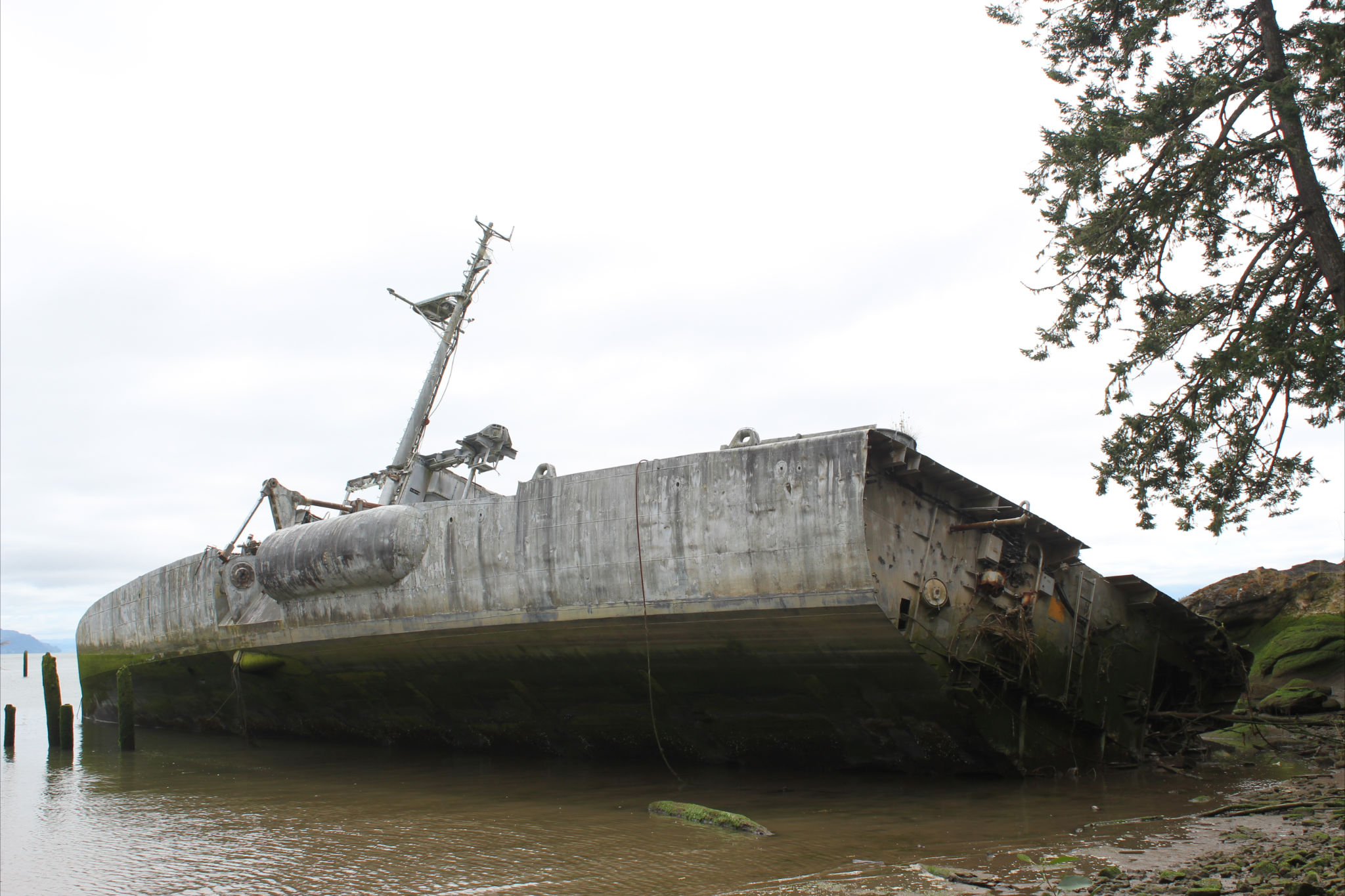
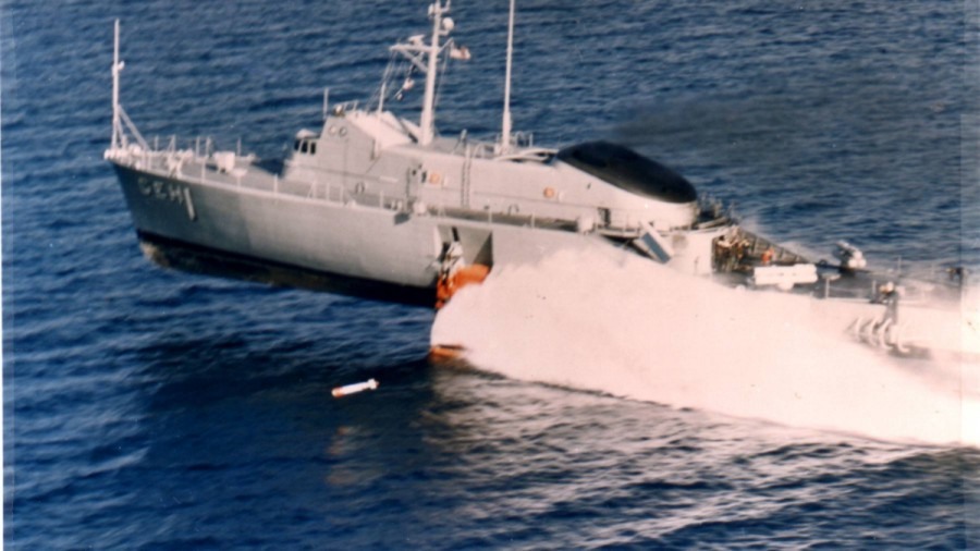
PHOTOS

PHOTOS

Alpine Foil Blade Rider Brett Curtis, Australia Delta Kite Boards Hydrofoil Board Chairs Williwaw by David Keiper Bates Technical College DOUG HELPER FOILS Dragonfly Evolo Electric PWC Formation Flying Futuristic Foils Guillermo Sureda Burgos Hi Foil, British PWC...

Hydrofoil Design Texts, Software, Sources, and Discussion

International Hydrofoil Society Correspondence Archives…

Hydrofoil Design Texts, Software, Sources, and Discussion
Descriptions, Advice, Sources of Information, and Requests For Help(Last Update: December 20, 2013)

Return to Posted Messages Bulletin Board


Books About Hydrofoils — Click HereMagazine Articles About Hydrofoils — Click Here

Suggest Additional Reference(s)


More Hydrofoil Sources…For Hydrofoil References in Technical Journals, Papers, and Books, Click Here

For More Bibliographies, Especially Sailing Related, Try the IHS Links Page)

Of course every IHS Newsletter is packed with articles about hydrofoils. To view an index of past articles in MS Excel, Click Here


Posted Messages

Fast Ships Paper

[5 Mar 02] Suggested paper for the next AMV CD-ROM:  Hefazi, Hamid; Orhan Kural; Hsun Chen; and Tuncer Cebeci, Professors; Eric Besnard, Adeline Schmitz, Kalle Kaups, and George Tzong, Research Associates, “Hydrofoil Design and Optimization for Fast Ships, Proceedings of the 1998 ASME International Congress and Exhibition Anaheim CA, Nov, 1998. Abstract: The paper presents a multi-disciplinary design/optimization method for the conceptual design of a hydrofoil based fast ship. The method is used to determine the maximum achievable lift-to-drag ratio (L/D) of an isolated foil-strut arrangement (hopefully greater than 50) at high transit speeds (greater than 75 knots) while lifting masses of 5,000 and 10,000 tons. First, the tools necessary for the study are presented. They comprise a panel method to compute three-dimensional flows around arbitrary configurations with a model for the free surface, a foil cross-section optimization tool, a strut cross-section design tool, and a structural analysis tool. The computational tools are then integrated into a multi-disciplinary design/optimization approach, which is applied to the design of single foil and biplane configurations. Results show that the goal of L/D = 50 is achievable for 75 knots (assuming that techniques can be developed for reducing the skin friction drag to a quarter of its nominal value) and, that for 90 knots, L/D ratios around 45 can be reached. The corresponding break horsepower requirements for 10,000 tons are around 130 khp and less than 200 khp, respectively. Full text posted at: www.csulb.edu/colleges/coe/ae/ae_dept/images/pdf/asme_paper.pdf. — Tom Speer (me@tomspeer.com) website: www.tspeer.com

Diesel Engineering Text (1 and 2)

[December 20, 2013] Author: Andrei Makartchouk
Title: Diesel Engine Engineering 2: Thermodynamics, Turbocharging, Dynamics,
Design, Control
ISBN: 0984634606
Available on Amazon.com

This book is a revised and extended edition of my previous book below, and provides the foundation for design of diesel engines based on traditional methods in
thermodynamics, dynamics, structural analysis, chemistry, heat transfer, applied analysis of system operation, and etc. This edition offers an additional material and examples for calculation of combustion process, thermal efficiency, heat release, NOx emissions, and etc. A diesel turbocharging is included into this edition also.

Providing detailed strategies to analyze, control, and design diesel engines, their systems, and major components, this text can be used as a manual for calculation of diesel engine thermodynamics and dynamics, design of turbocharging, evaluation of structural mechanisms, and modeling of diesel engine systems for optimal performance, efficiency, and maintenance in marine, industrial, automotive and genset applications.

Thank you, Andrei

Speed at Sea

[5 Feb 02, updated 17 Feb 03] Note the webpage URL for Speed at Sea, The Journal for Fast Ship Operators: www.rivieramm.com/sas/. — Robert Gore, Circulation Manager, Speed at Sea & Offshore Support Journal, Riviera Maritime Media; Tel: +44 (0)20 8364 1441 ext6; Fax: +44 (0)20 8364 1331 (E-Mail Address: robert.gore@j-l-a.com).

General Question

[13 Jan 02] Got any blueprints for hydrofoils? (Leprocaun1@aol.com)

Response…

[13 Jan 02] This inquiry is a bit terse, but here goes: We do not offer blueprints of any kind. If you will go to the popular magazines section of the IHS website you will find at least one old magazine that came with blueprints for adding foils to a motor boat. The next month’s issue provided plans for building the boat used in the first article. You can get copies of old magazines by watching the eBay auction site or by checking with a local antiques dealer or other seller of old magazines. On a larger scale, you should go to the links page of our website and find the link to Harry Larsen’s website on TALARIA III. He added a fully submerged foil system with Automatic Control System to a Bayliner cabin cruiser. If it is sailing hydrofoils you are talking about instead of motor boats, you will find quite a bit of correspondence posted from people who have built hydrofoils and who might be willing to help, but no plans are available directly from IHS. If you are talking about model hydrofoils instead of full-size hydrofoils, then there are some possibilities for plans or kits, both for motor and sail powered R/C models or static models… the posted correspondence on the site covers both of these topics. I hope I have answered your question… you gave me no details to work with! — Barney C. Black (Please use the BBS to reply)

Source of Marine Documents on Web

[13 Jan 02] There’s a fantastic source of books and studies at http://books.nap.edu/, many of them available to download and read or print out. There’s an extensive collection of marine documents. Hit the “Browse Categories” button to see the range.  http://books.nap.edu/books/NI000359/html/ takes you directly to last year’s Twenty-Third Symposium on Naval Hydrodynamics (2001), which is what led me to the overall site. — William Hockberger (w.hockberger@verizon.net)

Analysis Software Release

[11 Nov 01] New Wave Systems, Inc. announces a major new version of ProSurf, its trimmed NURB surface program for the design and analysis of boats and ships. ProSurf 3 is twice as large as ProSurf 2 and costs only $795, less than half the price of the previous version. In addition, ProSurf 3 contains capabilities not found in any other program at any price. Use ProSurf 3 as your primary hull design and analysis tool or use it as an add-on to your existing suite of CAD programs. See www.newavesys.com for complete details and a limited use, full working demo. Stephen M. Hollister (shollist@home.com)

Need Copy of 1968 Report

[4 Oct 01] I am looking for the following report: “The skin friction of a hydrofoil near a free surface” John C. Gebhardt. October 1968. Do you know anybody who has a copy of this report? — Günther Migeotte (gunther@cae.co.za) Dept. of Mechanical Engineering, University of Stellenbosch; Banghoek Rd; Stellenbosch 7600; South Africa

NACA Reports of Interest to Hydrofoil Designers

[16 Sep 01] The U.S. National Advisory Committee for Aeronautics (NACA) was chartered in 1915 and operational from 1917-1958. The National Aeronautics and Space Act of 1958 created the U.S. National Aeronautics and Space Administration (NASA) from NACA. According to the 1999 NASA Technical Manual NASA/TM-1999-209127 A Digital Library for the National Advisory Committee for Aeronautics by Michael L. Nelson of Langley Research Center, Hampton, Virginia, “The main product of NACA’s research was its multi-tiered report series. Although the exact number of NACA reports published is unknown, most estimates place this number between 20,000 and 30,000. This collection of work remains in high demand even today, especially in the areas of general aviation and the basic fundamentals of flight. Unfortunately, although significant collections of NACA documents exist at a handful of NASA centers, universities and other government and industrial research laboratories, no single library contains a complete collection. Even what constitutes a complete NACA corpus is subject to debate. Furthermore, because of their age, high circulation, and acid-based paper, many of these reports are in poor condition and will cease being serviceable in the near future. Conversion to digital format [and dissemination over the World Wide Web — begun in 1995 and ongoing –] is necessary for preservation as well as for wider dissemination.” The NACA Technical Report Server (NACATRS), the digital library (DL) that serves the NACA collection can be accessed at http://naca.larc.nasa.gov/. NACATRS offers browsing and keyword searching of its holdings. The NACA publications are scanned, but… “Optical Character Recognition (OCR) is not being applied for the NACATRS, primarily because the format of the NACA publications are often pages of equations, tables, charts and figures, none of which are well suited for OCR. Instead, the report is converted into a combination of GIF and PDF files for easier WWW dissemination… The first NACA Reports were issued in 1917, but TNs and TMs did not appear until 1920. The early publications were often either translations from European aeronautics works or authored by universities or other federal or military research laboratories. This is because NACA was initially truly a committee of aeronautically interested organizations rather than a federal agency in present context. As NACA acquired its own staff and developed its own research facilities, the number of publications authored by non-full-time NACA staff decreased. NACA published in a variety of internal report series. Currently [as of April 1999], the NACATRS holds the following NACA publications series:

  • Reports – NACA reports were considered to be the final and complete documentation on a subject or project and they often superceded one or more other NACA publication types. NACA Reports are sometimes (erroneously) referred to as ‘NACA Technical Reports.’
  • Technical Notes (TNs) – Technical Notes were the basic unit of the research report series. Some early TNs were translations of foreign works.
  • Technical Memorandums (TMs) – TMs are translations of foreign works. The TM series probably replaced translations in the TN series.
  • ‘Wartime Reports’ – Reports produced specifically for World War II research, they were declassified after the conflict. Due to their urgent nature, they frequently received little editing when written, and no editing was done after they were declassified. The moniker ‘Wartime Reports’ was added when they were declassified; previously they were issued as Advance Confidential Reports (ACRs), Advance Restricted Reports (ARRs), Restricted Bulletins (RBs) and Confidential Bulletins (CBs).
  • Research Memorandums (RMs) – RMs were initially restricted, and represented initial or limited scope results, and thus received less editing and preparation than other report series.

“NACATRS currently does not include:

  • Annual Reports – Annual Reports were simply the concatenation of a single year’s NACA Reports (i.e., excluding TNs, TMs, etc.). Inclusion of the NACA Reports in NACATRS implicitly includes the Annual Reports.
  • Aircraft Circulars – Reports published in the 1920s-1930s that reviewed the design and performance of contemporary aircraft (one AC per vehicle).
  • Conference or Journal Preprints – We are unaware of how many items this would include. However, their content would likely be covered in a Report or TN, so this exclusion is probably negligible.
  • Books – No books by NACA authors are included.”

Now, of course, the question is: in all this mass of technical data, which reports are of interest to hydrofoil designers? — Barney C. Black (Please use the BBS to reply)

Response…[16 Sep 01] Besides Report 1232 A theoretical and experimental investigation of the lift and drag characteristics of hydrofoils at subcritical and supercritical speeds, and Report 918 Theoretical Motions of Hydrofoil Systems, there’s TN 4168 A method for calculation of hydrodynamic lift for submerged and planing rectangular lifting surfaces, which also deals with hydrofoils. Some of the reports dealing with lift and drag of biplanes can be used, since the linear approximation of the free surface effects gives the same solution for a hydrofoil as the lower wing of a biplane. There are also reports on planing surfaces, which can be useful for hydroskis and for predicting the drag of hulls at takeoff. See Report 1355 A theoretical and experimental study of planing surfaces including effects of cross section and plan form, and TN 4187 High-speed hydrodynamic characteristics of a flat plate and 20 degrees dead-rise surface in unsymmetrical planing conditions. In general, the NACA reports are a very useful source of information on a lot of topics. — Tom Speer (me@tspeer.com) website: www.tspeer.com

Russian Hydrofoil Documents in English Translation…

[26 Jun 01] How does one get hold of NAVSEA (Naval Sea Systems Command) translations of Russian papers on hydrofoils etc. I have a number of references. I noticed in some IHS newsletters that Bill Buckley refers to the Naval Surface Warfare Center- Carderock Division Technical information service for such papers. Is this the correct place and do you have a contact address for them? — Gunther Migeotte (gunther@cae.co.za)

Responses…[4 Jul 01]The NAVSEA Library is no more. Not sure where these translations may have gone. The Pentagon library is a possibility but I don’t know what their policy is for access. — Mark Bebar (bebar@foils.org)

[4 Jul 01] In connection with the Advanced Ship Data Bank at the David Taylor Naval Research Center, to my knowledge there were never any Russian report translations entered into it, and I am quite familiar with the Data Bank contents. — John Meyer (president@foils.org)

 Wave Theory Sources…

[15 Apr 01] I am trying to see how water waves work, mainly deep water waves. They describe a circular pattern of the water particles, and some sites mention about a slow progression of water particles as the waves pass. The sites have not been detailed enough so I am still searching. — Gilbert Schmidt.(docscience@hotmail.com)

Response…[15 Apr 01] There’s a comprehensive treatment of ocean waves and the motion of boats in waves in Principles of Naval Architecture Vol. III, available from SNAME. Another classic is Theory of Seakeeping by Korvin-Kroukovsky (1961), also from SNAME. If you do a web search on “polyspectra” you will find some modern material on current research. — Tom Speer (tspeer@tspeer.com); website: http://www.tspeer.com; fax: +1 206 878 5269

[15 Apr 01] I would think most good general oceanography texts would provide this. I have one that has what I think is quite a good overview: Essentials of Oceanography, 3rd Edition, by Harold V. Thurman, Merrill Publishing Company, 1990. If you find it, “Chapter 9 – Waves” is simple and clear. Other books by Willard Bascom, B. Kinsman, and G.L. Pickard would probably give good treatments. (Bascom had an article in a 1959 issue of Scientific American that’s good, also.) — Bill Hockberger (w.hockberger@verizon.net)

[4 Mar 01] The clearest description of deep water waves I’ve seen is in Principles of Naval Architecture (New York: SNAME, 1967, 7th Printing 1986) edited by John P. Comstock. It is in Chapter IX “The Motion of Ships in Waves” by Edward V. Lewis, in particular Section 1 “Ocean Waves.” I would guess that this, or a later edition, is still available through SNAME. — John S. Pattison

[4 Mar 01] Easiest rules of thumb (theory not withstanding): 1. Wave pitch is 20X wave height. 2. No significant wave action below 2 wave heights. — Kobitz, Nat (KobitzN@ctc.com)

Foil Design Code…

[4 Jan 01] The XFOIL airfoil design/analysis code has been recently placed in the public domain. It can be downloaded at http://raphael.mit.edu/xfoil. I suggest this as a link for your site. — Mark Drela (drela@mit.edu)

Need Copy of 1994 Shanghai Conference Proceedings…

[17 Feb 01]I am looking for the following conference proceedings: International Conference for New Ship Technology into the 21st Century (NEWS-TEC’94). The conference was held on Shanghai, China in 1994. It has a few papers about the hydrofoil developments in China. The Office of Naval Research (ONR) had a copy which they tell me they destroyed?! Can you suggest anybody else who would have a copy of this conference proceedings? — Günther Migeotte (mailto:gunther@cae.co.za)

Response…[18 Feb 01] You may contact The Shanghai Society of Naval Architects & Marine Engineers. Its e-mail address is ssname@uninet.com.cn. Fax: 86-21-64721270. The name of the society’s secretary is Mr. Bing-Jin YE. — Shitang Dong (stdong@online.sh.cn)

Hydrofoil Equations Needed…

[13 Oct 00] Perhaps you could help in suggesting a source for the following. I am interested is obtaining a ‘cookbook’ type set of ‘simple’ equations and/or graphs to provide basic engineering guidance for a foil placed in water moving uniformly at about 10 mph and producing a lift of about 150 lbs.. I am not looking for sophisticated mathematics or optimized configuration. It is particularly important that the all the units used be clearly defined. — David Banks (sagamore@cvinet.com)

Fluid Dynamic Drag and Fluid Dynamic Lift

[6 Jun 00] I notice that copies of these two out-of-print, self published books, Fluid Dynamic Drag by Sighard F. Hoerner (1965) and Fluid Dynamic Lift (1975) by Hoerner and editor Henry V. Borst (published posthumously) have gone up for auction on www.ebay.com. These remarkable technical sources cover their respective subjects pretty close to 100%. — Barney C. Black (Please use the BBS to reply)

Responses… [6 Jun 00] I have 1 or 2 copies of the 2nd edition, which I believe this is. I also have a copy of the 1st edition, which I contributed to, when I was at Cornell Lab. — Nat Kobitz, (KobitzN@ctc.com)

[6 Jun 00] These excellent reference books were frequently used back in the days when we were designing hydrofoil boats. A must for designers. — Neil Lien (nlien@inwave.com)

Planing Hull Specifications…

[5 May 00] I am a university student studying ocean engineering and I was wondering if you could assist me in gathering some information on planing hull specifications for one of my assignments. — Daniel Lewis (31322172@students.amc.edu.au)

Response…[5 May 00] References follow:

  • Savitsky, Daniel, “Hydrodynamic Design of Planing Hulls” , Marine Technology, Vol 1, No.1, October, 1964
  • DuCane, Peter, “High Speed Small Craft”, Temple Press Books, London, 1964, 3rd Edition.
  • Blount, D.L., “Small Craft Power Prediction”, Volume 13, No.1, SNAME Transactions, 1976.
  • Heller, S.R. & H. H. Jasper, “On the Structural Design of Planing Craft”, Quarterly Transactions, RINA, July, 1960.
  • Allen, R. G. and R.R Jones “A Simplified Method for Determining Structural Design-Limit Pressures on High Performance Marine Vehicles” Paper No. 78-754, AIAA/SNAME Advanced Marine Vehicles Conference, San Diego, CA, April, 1978
  • Spencer, J.S., “Structural Design of Aluminum Crew Boats”, Marine Technology, Vol. 12, No.3, July 1975
  • Silvia, P.A., “Small Craft Design: Structures”, paper presented at Small Craft Engineering Symposium, University of Michigan, October 1971

— Ken Spaulding (secretary@foils.org)

Automated Lift Formula in MS Excel…

[28 Jun 00] I have placed an Excel implementation of Konstantin Matveev’s lift formula on my web page. — Harry Larsen (talaria@foils.org)

Force Model…

[23 Jan 00] I am looking for a theoretical model of the force of bearing on a supercavitating hydrofoil or the name of a French research laboratory that is working on the subject. Do you know whether there are some French ships with supercavitating hydrofoils? — C. Gouel (cgouel@libertysurf.fr)

Porpoising Question…

[23 Oct 99] I am a Spanish student, and I have read something about porpoising, but I would like to know something more about this effect. Could you give me some information regarding porpoising phenomena? F. Blasco (rbl00003@teleline.es)

Response…[9 Nov 99] To answer your request on information about porpoising. I assume you are interested in porpoising of planing hulls and the possible effects of hydrofoils. Porpoising of any high speed vessel usually takes place when the trim of the vessel is too high in relation to the amount of lift being generated. There are some papers available which give porpoising limits or planing hulls. A good start would be “Hydrodynamic Design of Planing Hulls” by Daniel Savitsky Marine Technology, Oct. 1964. I will have to look through my literature for more references. Hydrofoils can aggravate or improve the porpoising limits of a hull depending mainly on the position and the amount of lift carried by the foils. A foil carrying a large fraction of the displacement placed quite far forward will likely result in an increase in trim for the vessel and result in earlier porpoising. A foil placed aft will improve the porpoising limits of the hull. There does not seem to be any easy way to determine what the exact effect of specific hydrofoil design will be on porpoising. Model testing remains the best way to find this out. If you can give me more information on the details of your problem, or if you have specific questions, I can be of more help. — Günther Migeotte (gunther@cae.co.za)

[24 Dec 99] Payne and Martin did reasonably definitive analyses of porpoising in the late 70s and early 80s. Their work was published in the Journal of Ship Research. www.sname.org — C. D. Barry (cdbarry@hotmail.com)

Calculations For Human Powered Hydrofoil…

[8 Oct 99] I am currently working on my master thesis. The aim is to develop a wing and ground and hydrofoil supported human powered water bike. And here is my question! Do you know how to calculate the spray drag of surface piercing foils and struts? Or where could I find information about these topic. — Carsten Lehfeld (lehfeld@cadlab.tu-berlin.de)

Response…[10 Oct 99] There was an excellent report on the subject of Spray Drag of Surface-Piercing Struts. It was written by R. B. Chapman many years ago, but it is a classic paper. — John Meyer (jmeyer@erols.com)

Flap Design for Hydrofoil-Assisted Catamaran

[8 Aug 99] I am looking for methods or examples of how to design a flap system with the mechanism for adjusting the flap angle being part of the vertical centre strut of the foil. The application would be for hydrofoil assisted catamarans. I am basically looking for conceptual ideas at present so that I have a good idea of what has been done before. The hydrofoil assistd catamarans are quite large and the foils are designed to carry 150t under dynamic load conditions so I need a system that is quite robust, and will not require much maintenance. — Gunther Migeotte (gunther@cae.co.za) (editor’s note: Congratulations to Günther for winning the FAST’99 competition for the best student paper).

Response…[8 Aug 99] Originally on the HIGH POINT, the hydraulic actuators for the flaps were located in the propulsion pods at the strut and foil interface. The actuator moved a crank attached to the fixed piviot shaft for the flaps. This would be a possible system for a catamaran if the foils are spanning across the two hulls. On the HIGH POINT, the strut/foil retraction was to lift the assembly straight up. Access to the pod was by drydocking. Thus, during modification, the actuators were relocated to within the strut, with actuator pushing an extension rod to a bell crank and then to the flap. The original concept in design was to design the forces so that the rod was always in tension to avoid bending forces and excessive bearing wear. I know that forces on the strut measured by strain gages proved that the loads downward were as great as the lifting loads. I do not know how this affected the flap loads. Maybe Bill Buckley can elaborate in this area. As for the follow on ships using the flap system, the modified HIGH POINT system provided the flap actuation system. Not knowing your configuration, I shall provide one area of caution. Originally on the HIGH POINT, the outboard foil section flaps controlled the roll. The center section controlled lift. In certain conditions like a quartering wave, the flaps were working against each other. The automatic control system algorithms were changed to provide an aileron control. FLAGSTAFF and her sister ships and PLAINVIEW used incidence controlled foils. The actuators were located in or above the struts with a control rod down to the foil. Again, the design made sure that the attachment point was always forward of the hinge point and the cp was aft of the hinge point of the foil, to avoid rod bending. I do not know any of the details of construction nor the causes and effects on the USS HAYES, which is a catamaran hull with a foil across the two hulls. Original trials detected that the ship porpoised under most conditions. The problem was studied about 20 or more years ago by the Navy, and some solution was achieved. Someone might be able to enlighten us as to the cause and cure. — Sumi Arima (arimas1@juno.com)

Response…

[8 Aug 99] Mr. Arima, Thank you for that information. This is exactly the type of information I am looking for: concepts and what kind of problems I can expect. The idea of placing the hydraulic actuators in the hull with torque rods to the flaps is good, I am going to look into that further. I was thinking along the lines of some mechanism down the vertical strut, but this is more complicated. We usually use an incidence control system on the foils to vary the lift. The foils are connected to the hull via a bearing, and a hydraulic actuator is positioned at the end of the vertical strut, giving a nice lever arm. In this application it is not possible, so a flap system is required. The system is only for lift control and not for ride control at this stage, so a single flap on each side will suffice. Concerning the USS HAYES, the porpoising on these type of vessels is a combination of various parameters: foil configuration and positions, foil loading, LCG, and the shape of the hull also influences things quite a bit. We have encountered similar problems in our model tests, but by adjusting foil positions and angles of attack we have always managed to solve the problem for the desired speed range. It is often a trade off between stability of some kind (porpoising, directional stability etc.) and resistance. The best resistance improvements with foils are usually located right at the stability limits of the vessel. So some trade off has to be made. Increased resistance for increased stability. — Gunther Migeotte (gunther@cae.co.za)

Response…

[8 Aug 99] First of all, flap actuation (i.e. fatigue) loads were a significant consideration in the design of flap actuation systems for Navy hydrofoil ships. This was not fully realized in the beginning and as a result several failures occurred in service. In hindsight there were two factors which lead to fatigue problems. The first was the generally poor high-cycle fatigue properties of the high strength materials involved. The second one, which was the real villain, was the large number of load cycles introduced at individual flap actuators by an autopilot which responded concurrently to a large number of sensors, i.e. height, pitch angle, roll angle, several accelerometers, etc. This was especially true during rough water operation. There were several unanticipated linkage failures during foilborne operation which got everyone’s attention. Of a less critical nature were worn out control bearings that were a maintenance headache especially those on the AGEH-1. These particular bearings were very large and highly loaded because of the foil incidence control system involved. A wear problem problem occurred over time on other hydrofoil ships at the interface between the fixed and rotating elements of the spherical bearings employed. This was solved by using helicopter type bearings which had a ceramic coating at the interface (i.e. “Kamatics Corp. bearings”). With respect to the magnitude of steady and cyclic loads to be considered in designing a flap actuation system, I have only general suggestions to offer. The steady loads can be estimated (up to the point at which cavitation occurs) by the methodology given in Theory of Wing Sections by Abbott and Von Doenhoff, Section 8.8. I believe this old but classic book is still published in paperback form by Dover Publications, Inc. The cyclic loads are an other matter because they are a function of autopilot design, foil and flap configuration, and the characteristics of the rough water environments involved. If your vessel is small enough to employ solid foils and flaps in a material which has relatively good fatigue properties (such as used in marine propellers) you may only need to give special attention to the bearings and rod end fittings if used. — Bill Buckley (wbuckley@erols.com)

Window Design For Hydrofoil Ships…

[8 Aug 99] I am working as a librarian for the Transportation Safety Board and someone here is looking for an information on hydrofoils. He wants to know if there is a standard for windows (or glass) for hydrofoils. The request is related to an accident that occurred in Lake Superior where one of the glass windows of an hydrofoil was broken by a wave. N.B. In one of your answers (taken from the International Hydrofoil Society web site) you mentioned as reference, the name of Mr. Michael Eames who worked for a Canadian naval project. Would it be possible to provide me a number/info in order to contact him? — Sylvia Mauro, Librarian, Transportation Safety Board of Canada (Sylvia.Mauro@tsb.gc.ca)

Response…[8 Aug 99] I have the following comments and one recommendation: I have not made any general survey of existing strength regulations for bridge and other types of windows so I have no comment specific to the inquiry about a standard for window design. I have on the other hand investigated a fair number of ship heavy weather damage incidents and can assure you that wave impact damage is the most common type of structural damage encountered in rough seas. Furthermore, I can state that naval architecture is out of touch with reality in the case of wave impact loadings, and that the design of windows to withstand wave impacts is the area most most in need of appropriate design criteria. The reasons for this are not hard to understand. First there is no set if seaway criteria existing that identifies realistic (i.e. actual) seaway conditions that must be withstood. Second, such load criteria as has evolved from service experience is expressed as an “equivalent static load.” In real life, the loading is dynamic, and of all components of a vessel which are subject to dynamic wave loads, windows are the most susceptible to failure because they can not absorb dynamic overloads by ductile behavior. The fact that the hydrofoil damage which occurred involved windows cannot be regarded as surprising, nor can the facetious IMO Code requirement be considered surprising either. With regard to obtaining an appropriate basis for window design I would recommend that you contact a naval architecture firm that designs bridge windows for commercial fishing vessels. I feel sure they will recommend an impact resistant material such as Lexan and a static loading which has withstood severe service. As far as a rational design criteria is concerned only my own First Principles Methodology will suffice, and that is developmental! — Bill Buckley (wbuckley@erols.com)

Response…

[8 Aug 99] Classification societies also specify design and test requirements for windows and portholes in their rules or guidelines for the construction of ships. Specific rules have been developed by some classification societies for high speed light craft (which cover hydrofoils also). Such rules are produced by Lloyd’s Register, Det Norske Veritas (DNV) and the American Bureau of Shipping (ABS) amongst others. The relevant ABS document would be the ‘Guide for Building and Classing High-Speed Craft’ of which the latest revision I am aware of is February 1997. Part 3, Section 20, Sub-section 8 of the ABS guide refers to window construction and testing requirements. This section gives requirements for the fitting of strong deadlights (covers which can be fitted over the windows in the case of encountering rough weather), window framing, mounting of the glazing in the frame, window thickness requirements and the need for hose (water pressure) testing. It is too difficult to duplicate that section in this email as it contains various equations. A copy of those rules could be obtained from ABS Americas or ABS Corporate HQ at the following addresses: ABS Plaza; 16855 Northchase Drive; Houston, TX 77060 USA; Tel: (281) 877 6000; Fax: (281) 877 6001; Email: abs-amer@eagle.org; or Two World Trade Center, 106th Floor; New York, NY 10048 USA; Tel: (212) 839 5000; Fax: (212) 839 5130; Website: http://www.eagle.org

  • The classification society rules or guidelines only apply to ships (or hydrofoils) which are built or classed by the society in question. I suspect the hydrofoil involved in the incident on Lake Superior may have been one designed in the former Soviet Union in which case it may not be easy to trace the original design requirement for the windows for that craft.
  • Michael Eames died a number of years ago. The Defence Research Establishment Atlantic (DREA) in Dartmouth, Nova Scotia at which he worked is no longer involved in hydrofoil design work.

I will finish with a sobering remark: Several years ago, a pilot boat was hit by a large wave within Port Phillip Bay in Victoria, Australia. These boats are typically of a solid construction with strong bridge windows, but despite this the windows were smashed in by the wave and one of the crew on board the boat was killed as a result. Although not directly related to your inquiry, the details of this incident may still be available through the Australian Maritime Safety Authority (AMSA). — Martin Grimm (seaflite@alphalink.com.au)

Determining Foil Size and Profile…

[21 May 99] Hi, I am a member of the IHS and am interested in building a small, fast hydrofoil sailboat. My question is: What is the average loading per square foot (or square inch) for a hydrofoil expected to go about 25 kts? Is there a quick formula for determining the size of the hydrofoil based on the weight of the craft and speed? — Jim Wolbert (wolbert@att.net)

Response…[22 May 99] I am afraid there is no quick and simple formula to settle questions of hydrofoil size and configuration. There is a great book with many design examples called the Aero-Hydrodynamics of Sailing. You can probably find existing boats in the same class as yours in the book and it will gives you the good and bad aspects of the existing designs. Hope this helps. — Marc Schafer (spaceboy@sgi.com)

2nd Response…

[1 Jun 99] There is also good design advice for the construction of hydrofoil sailboats in the book Hydrofoil Sailing, the full details of which are listed in the IHS website bibliography. That book covers options for foil configurations, lift and drag estimation, forces acting on the craft while foilborne and aspects of the construction of the foils. A representative value of foil loading can be calculated for the modified Tornado Catamaran ICARUS described in the book. This sailboat was fitted with split surface piercing hydrofoils forward and aft. The forward (main) foils carry some 80% of the 600 lb (272kg) total weight over a vertically projected foil area of 8 square feet (0.743 square metres) during takeoff. That corresponds to 60 lbs/sqft (293 kg/m2). This craft lifted out of the water at about 10 knots. For ICARUS, as the speed increases the foils will rise further out of the water and the submerged foil area will reduce even though the craft weight remains the same. As such, the foil loading could increase significantly beyond the value calculated above for the takeoff speed. With too great a foil loading, you will run the risk of cavitation or ventilation of the foils. Lift generated by a hydrofoil, like an aerofoil, is dependant on a number of parameters. To accurately predict lift the following parameters should be taken into account (some of these parameters are taken into consideration in formulae provided in Hydrofoil Sailing):

  1. Lift versus Angle of Attack characteristics of the 2D foil section adopted (such data is available in books providing data on aerofoil sections).
  2. The angle of attack of the foil.
  3. The submerged foil area.
  4. Aspect Ratio of the submerged portion of the foils (i.e. Span divided by Chord Length).
  5. The other geometric aspects of the foil including sweep, twist and taper.
  6. The dihedral angle of the foil.
  7. The speed of the foil.
  8. The proximity of the foil to the surface of the water.
  9. Downwash effects of one foil on another downstream.

The speed of 25 knots which you are aiming at is fairly high for a sailing craft. Should the drag of the foils at 25 knots be greater than the driving force available from the sails, then the targeted speed will not be achieved. Consequently, the lift generated may be insufficient to fully lift the hull out of the water.

An approach to developing a hydrofoil sailing craft is to first sketch the layout of the craft, including a ‘best guess’ at the possible foil configuration. The next step is to get good estimates or measurements of weights of items that will make up the craft including the crew load. If you are using an existing sailing craft design as the basis of your hydrofoil, the task of obtaining the weight details may be easier. In that case, you may also be able to establish what speeds are attainable for that type of sailboat without foils fitted. Don’t expect the addition of hydrofoils to work wonders for the performance of the craft. Perhaps you could assume 10-20% additional speed beyond the hullborne speed. To get you in the right ballpark for sizing the foils, use the following formula (I have given units in metric):

L = 0.5 x CL x RHO x A x V2

Where:L = Lift (or the total craft weight supported by the foils) in Newtons

CL = Coefficient of Lift, say between 0.25 and 0.4

RHO = Water Density, 1025 kg/m2 in salt water

A = Total vertically projected area of submerged foils

V = Boat speed in metres per second (i.e.: speed in knots x 0.514)

Assuming that you can achieve 25 knots (V = 12.86 m/s) and you have estimated your craft weight (L) well, the only unknown parameter in the equation is the vertically projected area (A) of all the foils. Choose the foil area such that lift coefficient (CL) is in the suggested range. I hope these suggestions are helpful and don’t lead to a complete failure! — Martin Grimm (seaflite@alphalink.com.au)

Foil Design For Twin Keel Sailboat – Guidance Needed…

[20 May 99] I am writing to ask for assistance in locating specific design information on underwater foils. I am doing a concept design of a twin keeled sailboat for which I would like to find lift and drag coefficients for a symmetrical cross section foil. I am a retired Livermoore engineer moderately capable in stress and vibration but weak in hydrodynamics. I am, e.g., ignorant as to how the shape of such symmetrical foils are characterized, i.e., by tabular values, by equation, or even perhaps by a NACA airfoil identification number. Of particular interest is the effect of aspect ratio, i.e., how the lift and drag parameters of a single keel compare to the ones for a double keel of half the chord and proportionally reduced cross section but of the same span or draft. That is, of double keel of the same wetted area as a conventional single one. Regarding the lift and drag coefficients, I have assumed that for the probable small angle of attack of a keel, the lift to drag ratio remains relatively constant for small changes in the angle. Here again however, unlike to angle of attack assumption, my ignorance is large. In thinking about the problem I have wondered if perhaps relevant information on the design parameters of the foils used for lifting high speed power or sailing craft out of the water might apply. Perhaps the such underwater horizontal foils are unsymmetrical as might also be the case for the self leveling vee type. But maybe their parameters are sufficiently close to those of symmetrical ones that this might be a good place for me to start. In the off chance that there might be a textbook in print on foil design, I would be happy to purchase it if you know of such. Published papers, or perhaps Master or Doctors theses might also be available. Or even Internet items of your Association. Or, as is likely, something that I am unaware of. Thank you in advance for whatever help you can provide without being too much of a demand on your time of patience. If the mathematics of my pipe dream are encouraging, I would be happy to share the idea with you. If at even greater odds there might come to be a prototype, I’d invite you for a sail somewhere in the San Francisco Bay area if it were not for the fact that I am semi-invalided with rheumatoid arthritis and occupy my spare moments now with thinking about sailing rather than actually doing it. — Jerry B. Cain (jerrybonline@thegrid.net)

Response…[29 May 99] I can’t help at all with the twin keel arrangements, but the single keel will act very much like a wing of twice the aspect ratio. A wing has drag of two types, form drag and induced drag. The form drag comes from the shape of the wing. The induced drag is caused by the energy lost to vortexes at the wing tip as the fluid moves from the high pressure area on one face to the low pressure area on the other face. The induced drag increases as the square of the coefficient of lift. The equation is Cdi=(1+delta)xCl2/(pi x AR) Where Cdi is the induced drag coefficient, Cl is the lift coefficient, and pi is 3.1415. AR is the aspect ratio. Delta is dependent on the wing shape. An elliptical wing has delta=0 and will be of the order of 0.1 for a rectangular wing. The actual lift will be Cl x area x dynamic pressure the actual drag will be (Cdf+Cdl) x area x dynamic_pressure The dynamic pressure is speed^2 x density x 0.5. A symmetrical aerofoil section, with thickness 12% of chord will give a form drag coefficient of 0.007 at zero angle of attack. At 5 degrees the lift coefficient is 0.6 and the form drag is 0.01. I use a program called Panda, from Desktop Aeronautics Inc. to calculate these. — Malin Dixon (gallery@foils.org)

2nd Response…

[1 Jun 99] First of all, I should warn you that all my hydrofoil experience is limited to what I have read rather than practised! Your concept design for a twin keel sailboat sounds very interesting. I believe the challengers for the most recent Americas Cup yacht race had used twin keels. If I recall correctly, twin in line skegs were fitted to both an Australian and New Zealand bid. In any case, I seem to recollect hearing that it was a little challenging to handle this arrangement. Perhaps you can try to establish the details of those entries?

To answer your questions as best as I can:

2D foil section shapes can be defined by both methods you have anticipated. Applied mathematicians and hydrodynamicists take joy in transforming the equation of a circle into equations for representative airfoil shapes as it is possible to calculate the lift on such ‘transformed’ 2D sections using purely theoretical methods. Tabular descriptions of foil shapes are however more common. A good review of 2D foil sections and their characteristics is provided in Theory of Wing Sections by Abbott and Von Doenhoff. When a foil section is described in a tabular format, the normal convention is to define a baseline through the leading edge (at the furthest most forward point) and trailing edge of the foil section. At a relatively uniform spacing from the leading edge to the trailing edge, but more finely defined in the first 30% of the chord length, the distance of the upper surface and lower surfaces of the foil section away from the baseline are specified. All data is given as a fraction or percentage of the chord length of the foil so that it can be scaled to any size of foil. In addition to this description, the radius of curvature of the leading edge is also provided as a proportion of the chord length. For the symmetrical section foils as you are interested in, the distance of the upper and lower surface of the foil away from the baseline are equal so only one distance needs to be quoted. A foil section shape commonly used for ship’s rudders, fin stabilisers and the like is the NACA 0015. I have used this to demonstrate the tabular definition of a foil section shape:

‘x’ is the distance from the leading edge of the foil section as a percentage of its chord length. ‘y’ is the distance from the surface of the foil away from the baseline at the corresponding ‘x’ position along the chord. Once again, ‘y’ is given as a percentage of the chord length.

(x , y) — (0.0, 0.000), (1.25, 2.367), (2.5, 3.268), (5.0, 4.443), (7.5, 5.250), (10, 5.853), (15, 6.682), (20, 7.172), (25, 7.427), (30, 7.502), (40, 7.254), (50, 6.617), (60, 5.704), (70, 4.580), (80, 3.279), (90, 1.810), (95, 1.008), (100, 0.158)

For this section, the leading edge radius is 2.48% of the chord length. The designation given to NACA foil sections has a pattern, but the full details are best obtained from reading books such as Theory of Wing Sections. A simple subset to illustrate the sequence is those with a number starting with ’00’. These are symmetrical sections where only the thickness to chord ratio (t/c) has been varied. In that series, the final two digits represent the thickness to chord ratio as a percentage, so for the NACA 0015 section, the thickness is 15% of the chord. The thickness is the widest point on the foil section. From the table above, it can be seen that the maximum thickness on the section occurs at 30% of the chord length behind the leading edge. At that point the distance of one surface away from the baseline (or in this case also the centreline) is 7.502% of chord length. The total thickness is double this amount, ie about 15%. A typical sailing boat keel section would probably have a thinner foil section unless it is also used for ballast purposes.

All the above points concerned the 2D section profile of a foil when end on. When you make reference to the Aspect Ratio of the foil, you are moving onto 3D aspects of hydrofoils or aerofoils (wings). As you are apparently aware, the Aspect Ratio is one element of describing the planform of a hydrofoil, ie its shape when viewed from above. The aspect ratio of a foil is defined as its span divided by its average chord. A word of caution here: most equations for lift and drag refer to the effective aspect ratio which is based on the effective span of the foil. If you have a foil attached to a wall, like say a rudder or keel below the hull of a yacht but in close contact with it, then its effective span is twice the geometric or physical span of the foil. The wall, or hull of the yacht in this example, acts like an image plane. Due to the presence of the hull, water flows over the real keel or rudder as if it was attached to a mirror image of itself. This is because no water can flow through the hull surface unlike at the tip of the keel where a tip vortex is created.

All other parameters remaining the same, a high aspect ratio is good for achieving a high lift to drag ratio. The best illustrations of this are the long narrow wings which are fitted to modern gliders. The aspect ratio of the wings of such gliders are in the range of 30 to 40 for high performance types and their shallow glide slope is a direct indication of their lift to drag ratio. Compare that to the inefficient stumpy wings of a fighter aircraft, good for their intended purpose, but lousy if you want efficiency!

Extending this to your sailboat, a single keel of say 1.0 metre geometric span and 1.0 metre chord (aspect ratio of 2 if the underside of the hull can be considered as a continuous wall) would have a lower lift to drag ratio than two keels each with a 1.0 metre geometric span and 0.5 metre chord (each having an aspect ratio of 4), even though the planform area is the same.

There is a down side… Regardless of whether you place the keels side by side or in line with one another, the combined lift to drag ratio will be degraded somewhat compared to that of two keel considered in isolation. This is because the keels will cause a downwash on one another. The degradation in lift to drag ratio will depend on the separation you are able to achieve between the keels. As an example, the lift and drag ratio on biplanes is still affected by the interaction between the upper and lower wings despite their spacing. I think that side by side keels may be preferable from a point of view of giving more predictable handling characteristics for the boat.

Regarding the lift to drag ratio, this does not remain very constant, even at small angles. For symmetric foils of high aspect ratio, the lift varies fairly linearly with increasing angle of attack starting at zero lift for zero angle of attack. The drag on the other hand is already non zero at zero angle of attack due to skin friction and profile drag and then increases roughly in proportion to the square of the angle of attack. Consequently, the lift to drag ratio is zero at zero angle of attack then rapidly climbs to its maximum value at angles of attack of as little as 3-4 degrees before falling again as the drag rapidly increases with further increases in angle of attack.

So, you can see that you need to achieve a fine balance if you want to develop an efficient sailboat!

Most text books on aeronautical engineering will give you the information you need to help with most aspects of the keel design for your concept (except perhaps the interaction between both keels as the angle of attack changes). If both keels are side by side, the text books should even provide you with a method of allowing for the so called ‘biplane effect’ described previously. All you need to do is exchange the density of air (about 1.223 kg per cubic metre) with the density of water (about 1025 kg per cubic metre in salt water) in the formulae that are provided. Another relevant source of information would be a naval architecture textbook, say Principles of Naval Architecture published by the Society of Naval Architects and Marine Engineers. This provides good guidance on the lift and drag to be expected from relatively low aspect ratio rudders. The equations in that text book can be converted to spreadsheet format without undue difficulty and this makes the calculation process quicker and easier. — Martin Grimm (seaflite@alphalink.com.au)

Follow-up Questions…

[7 Jun 99] Does the profile drag coefficient term remain substantially at .007 over the likely ranges of angle of attack and boat velocity? Secondly, does the apparent double aspect ratio of the keel due to the wall effect still obtain if the keel is at an angle to the hull rather than being perpendicular? — Jerry B. Cain (jerrybonline@thegrid.net)

The Race…

[27 Apr 99] We are currently designing three 9′ horizontal foils for my 60′ long and 59′ wide 15.000# trimaran with 3,000 sq. ft. of sail. (ex Ker Kadelac) They are being designed to swing aft and up in case of collision. Would appreciate info from anyone experienced with this type of application. Also, interviewing ambitious students willing to get their hands dirty. — Peter Murray tel.1.561.708.7008; fax..219.2270; (therace2000@ hotmail.com)

Student Wants Info…

[3 Apr 99] I’m a French mechanical engineering student and I’m searching for some information about hydrofoil design (theory and design). Can you give some more information about the subject ? (web site, books, etc.) — Cédric Kuchler (Cedric.Kuchler@ismcm-cesti.fr)

A Good Book…

[31 Dec 98] As a much younger armchair participant, fueled by my dad’s experiments in submerged hulls, ‘bulbous bows’ (way before they showed up on Japanese tankers !), and solid airfoil/wingfoil sails, I read a great book Sailing Hydrofoils by James Grogono and two of his associates. David’s experiments and accomplishments were mentioned several times – he DID it, not just wrote about it. Thanks for the vicarious moments, David! – Eric Wuolle (eric.wuolle@home.com)

Response…[6 Jan 99] For those who are interested in sailing hydrofoils, and who want some good design guidance and a review of some of the craft that had been built by the early 1970s, the full details of the book to which Eric referred are: Hydrofoil Sailing; Alan J. Alexander, James L. Grogono and Donald J. Nigg; published in Great Britain in 1972 by Juanita Kalerghi ISBN 0 903238 00 4. The book covers the full range of design considerations for hydrofoil sailboats in an easy to read format. — Martin Grimm (seaflite@alphalink.com.au)

Micro-hydraulics…

[31 Aug 98] I Am VERY interested in micro-hydraulics. Do you know who has info? — Nat Kobitz (Hynat@aol.com)

Seaplane Applications…

[20 Jun 98] I am looking for a simple equation to estimate lift and drag for a submerged hydrofoil and possibly one to determine lift and drag as the foil lifts out of, and finally off, the water. This is for a seaplane application. For example: Coefficients of lift and draft as a function of aspect ratio, angle of attack, and velocity. I would be very pleased to get some links or other references to tests or research related to this application. — Tom Croswell

Response…

[8 Jan 99] There is some good guidance on estimating lift and drag of hydrofoils for preliminary design purposes in the following reference: Eames, M.C., “Principles of Hydrofoils” in the book HIGH-SPEED SMALL CRAFT by Peter Du Cane, David and Charles (Holdings) Limited, Devon, 1974, Fourth Edition, Chapter 3, pp 12-54. This chapter of the book was written by a man who really understood hydrofoil design as he was deeply involved in the Canadian naval hydrofoil project which led to the construction of FHE-400 BRAS d’OR. Michael Eames has presented his notes in a way that can be digested with relative ease. With the exception of the influence of the water surface and of cavitation, the lift and drag of a hydrofoil can essentially be determined using the same principles as applied for aircraft wings. There are many aeronautical engineering texts which provide such information. — Martin Grimm (seaflite@alphalink.com.au)

Read a Good Book Lately?

[16 Jul 97] I’m becoming very interested in boat foils as in my previous interests, gliding and building of composite structures, there seems an obvious similarity to boat foils. Also I’m fed up going everywhere at 8 knots in the Sigma 33 I presently crew on. Can you recommend any good semi technical books on the subject to familiarize myself better with the problems of foils. It would seem to me that aircraft technologies should be pretty similar but we perhaps don’t need such big surface areas. — Wayne Richards (e.w@virgin.net).

Response…[5 Nov 97] According to veteran IHS member Sumi Arima (arimas1@juno.com): In answer to your question on text books, there is no one good book on foils. Most of the hydro types use Horner’s books Fluid Dynamic Lift and Fluid Dynamic Drag. When we bought a set, the only source was from Horner’s widow. College libraries generally have it, but local libraries do not.” There is also Principles of Naval Architecture, which is a two volume set published by the Society of Naval Architects and Marine Engineers (SNAME). IHS maintains a list of hydrofoil-related articles and papers, but most are hard to find. Another suggestion, the Amateur Yacht Research Society publishes quite a few technical papers, and there is an index of titles on their site… you may see something that addresses your specific need and can contact them for a back issue of the journal containing articles in which you have interest. You should also explore the extensive technical links at the Links for Yacht Designers web site. Finally, if you have specific questions, I can try to forward them to technically oriented members that can discuss them with you. Also I can post questions on the IHS website and solicit responses from all who visit the site. — Barney C. Black (Please use the BBS to reply)

Hull Resistance Calculator…

[25 Jul 97, updated 27 Dec 00] I have been experimenting with a hull resistance calculator, based on Joe Norwood’s book (chapter 3). A draft version of this is available online at http://www.users.globalnet.co.uk/~fsinc/yachts/spreads/fred.htm. I would like some feed-back from potential users, particularly from those who complained that they could not understand the book. Please send any suggestions for improvement. Does anyone have any ideas about anything else that they would like to have an on-line calculator for? — Fiona Sinclair (fsinc@globalnet.co.uk). Yacht Research website: http://www.users.globalnet.co.uk/~fsinc/yachts/


<Back to Top of Page> <Go To IHS Main Page> <Return to Posted Messages Bulletin Board>


Hydrofoil History – Pioneering Vessels and Pioneering People

Hydrofoil History – Pioneering Vessels and Pioneering People

International Hydrofoil Society Correspondence Archives…

Hydrofoil, Rudder, and Strut Design Issues
(See also links to design texts and other technical information sources on the IHS Links Page)
(Last Update: 11 Nov 03)Return to the Archived Messages Contents Page
To search current messages, go to the Automated BBS


Correspondence

Where is Foil Design Data?

[11 May 03] Where do I go for specifics about foil design? As in how do I determine the size, aspect ratio, need for winglets, shape, (inverted T vs. inverted Y vs. horizontal V), NASA foil specification . My plan calls for a single foil fully submerged with all control being accomplished with above water airfoils (pitch, roll, direction). Everything above water is conceptually set, but I have limited understanding / knowledge about foils. I understand that there are arrangements combining a lower speed and higher speed foil on the same vertical column, with some type of grooving on the higher speed foil to prevent cavitation at limited angles of attack. With respect to the website http://www.supramar.ch/ there is an article on grooving to avoid cavitation. I anticipate a limited wave surface (off shore wind) so elevation could be limited, and the initial lifting foil would be unlikely to be exposed to resubmersion at speed. Supramar is willing to guide/specify the grooving at no charge, but I need a foil design for their review or at least that seems to be the situation. I have not actually asked for a design proposal. Maybe I should. Actually it is hard to know if my request would even be taken seriously. They did communicate initially but subsequent emails have been unanswered. Any instruction, constructive criticism, or guidance would be appreciated. Of note the current land speed record for a kite/sail powered tricycle vehicle is just a touch over 72 mph in 40-50 mph winds. — Duncan Coolidge (jcoolidg@tds.net)

Response…[11 May 03] We frequently get requests like this. The answer is not simple, but there is a lot of help within the organization and on the website. I advise first checking out the site, and at the same time order a copy of the Advanced Marine Vehicle (AMV) CD-ROM #1 announced on the site. This CD has a lot of foil design info. — John Meyer (jmeyer@erols.com)

What NACA Series is Best?

[15 Mar 02] I am studying in Naval Architecture Department, Ocean Engineering Faculty, Sepuluh Nopember Institut Of Technology, Surabaya Indonesia. Before I complete my studies, I must do experiments as requirement from my college. I want to experiment with about lift and drag for a foil of a Hydrofoil Craft. This experiment is using Computational Fluid Dynamic (CFD) with ANSYS 5.6. But I am confusing about what NACA Foil Series is suitable for Hydrofoil Craft, and what the principal reason for choice this NACA Series. — Hot Pungka Purba (pungka@yahoo.com)

Response…[15 Mar 02]You haven’t said what the requirements are for your section. Since you mention NACA foils, I assume that you are interested in the subcavitating speed range. You need to have some idea of the range of lift coefficients are required of your foil – this is driven by the load the foil has to carry and the variation in angle of attack the foil will experience as it goes through waves. Something like Cl = 0 to 0.6 with a design Cl = 0.3 would be typical. The intended speed range for the vessel is critical – what are the takeoff, cruise, and dash speeds? And you need to know how the craft will be controlled – will the foils be surface piercing or fully submerged, and will they change incidence or have flaps?

I believe there are four key problems in subcavitating hydrofoil section design. First, you want to avoid separation because this invites ventilation as well as causing drag. Second you want to avoid cavitation. Of course, you also want low drag, and fortunately the things you do to get a high cavitation speed and avoid separation are also good ways to minimize the drag. Finally, the section may be operating close to a free surface, and this modifies the velocity distribution about the foil.

Since cavitation begins when the lowest pressure anywhere on the foil drops below the local vapor pressure of water, you want to minimize the maximum velocity. That means no sharp pressure peaks allowed! At the same time, you want the average velocity over the top surface to be as high as possible so as to produce the most lift. This drives the design to shapes which have long, flat pressure distributions – shaped like building with a flat roof.

The NACA sections which have this type of rooftop velocity distribution are the 6-series laminar flow sections and the earlier 1-series (i.e., 16-012, etc). The 1-series sections have a shallow favorable pressure gradient back to 60% chord, but they have a highly convex pressure recovery that is not necessarily a good characteristic if one wants to avoid separation at the trailing edge. So a comparable 6-series section (say, 66-XXX) would probably be a better bet than the corresponding 16-XXX section.

There are other more modern hydrofoil sections, such as the Eppler designs. Try to get his book, “Airfoil Design and Data”. It is out of print, but your engineering library should be able to find it. He talks about the philosophy of hydrofoil design and has several sections specifically designed to be hydrofoils.

You can also design your own hydrofoils using XFOIL, which you can download for free. XFOIL is more modern code than the Eppler code, but you can still design sections like Eppler’s using XFOIL. This would be a good start to analyzing with ANSYS because ANSYS doesn’t have the inverse design capability of XFOIL but it does have a more powerful analysis capability. So you would be able to compare the experimental results, the inviscid + integral boundary layer results, and the Navier-Stokes CFD results, at least for subcavitating flows.

Simulating the two-phase flow that results from cavitation would be a difficult challenge! But it has been done, and this makes a Navier-Stokes method worthwhile. Unfortunately, much of the research has been done using NACA 4-digit sections (like 0012, 0015), and I suspect this is either out of ignorance as to what makes a good hydrofoil, or perhaps because these are bad hydrofoils and cavitate more easily!

Say you are concerned with a fully submerged hydrofoil with flaps to control the height of the vessel. As the boat flies through waves, the orbital velocity of the waves will change the angle of attack on the foil and thus the lift. The control system will try to compensate for this by moving the flap. If the boat is flying along perfectly level, a good approximation of a perfect control system would be one that maintained a constant lift coefficient on the foil as the angle of attack changed. Thus you need to consider three cases: zero angle of attack with the flap at neutral, positive angle of attack with the flap deflected up, and negative angle of attack with the flap deflected down. The larger the flap deflection, the greater the angle of attack change that can be tolerated while still maintaining the same lift coefficient, and the higher the sea-state in which the ship can operate. For each of these three cases, the peak velocity will occur on a different part of the foil. You would want to design the foil so that the value of the peak velocity is the same in each case. This will give you the highest speed without cavitating. But larger flap deflections and a greater angle of attack range means higher maximum velocities and thus a lower operating speed without cavitating, so there’s a tradeoff between the ability to operate in rough seas and the vessel’s maximum speed. It’s an interesting design problem! But one that comes back to knowing the original requirements in order to design (or select) the appropriate section.

Take a look at …

— Tom Speer (me@tspeer.com) website: www.tspeer.com

Just after I pushed the “Send” button for the preceding email, I found a good link about using Fluent to calculate cavitating flows, but I didn’t save the link. I can probably find it again if anyone is interested. I’ve also thought some about why the 16-XXX sections are so popular for hydrofoils over the 6-series, and I think it must be because they have a much thicker and stronger trailing edge. So perhaps I was too hasty in recommending the 6-series because they may not be practical for the very high loadings of hydrofoils. Flexing of the trailing edge can lead to singing, too. By the way, there are some interesting papers at U. Mich. on their large-scale hydrofoil (8′ chord!) test. — Tom Speer (me@tspeer.com) website: www.tspeer.com

Foil Design Guidance Needed

[4 Feb 02] I am restoring and optimizing a 1969 Irwin 24. Its keel has an “L” design fin and ballast torpedo. The foil consists of a one inch thick steel plate encased in fiberglass and faired to a section that is similar to NACA 00-series sections through station 6; then tapers to a blunt trailing edge. I have some experience with symmetrical foil optimization; however always with sections in the 8% to 12% thickness range (and no data on less than 6% thickness). I have never implemented a foil less than 7% (even when strength and ballast were not considerations) and I am contemplating taking one of two options:

  1. Maintaining the thin section, leaving the foil in tact (excepting minimal fairing) through section 6, tapering the trailing edge to 1/16th inch and squaring off (this may require increasing the span ~3 inches); making the foil a very close approximation of a NACA 00-series section with 4% thickness.
  2. Building up the existing foil section to a NACA 0006 or NACA 0008 section (this may require increasing the span ~1 inch and add approximately 100 pounds to the displacement).

Option 1 is far less work, but would change the plan form design slightly. I am not particularly worried about moving the center of lift slightly back because I have removed a 6 inch deep skeg that was a retrofit between the keel and rudder. In any event I am keen on cleaning up the trailing edge. Option 2 would be a good deal of work that would require some benefit to justify undertaking. The plan form data on the keel is as follows: Span = 24 inches, Chord = 45 inches, Max thickness = 2 inches, Sweep Angle = 45 degrees. The torpedo height is 12 inches, the torpedo is V shaped where it meets the foil (120 degrees at the foil interface and the at the bottom) and has a total length of 58 inches. Total displacement is 3000 pounds. Thanks for any guidance you can afford me. — Tom Graham (TGraham@entergy.com)

Response…[6 Feb 02] Paul Bogataj had an article in Sailing World a while back concerning keel sections and leading edge shapes. I’d download XFOIL and use it to look at different sections. You can put in your section as it is, NACA sections for comparison, and use it to make modifications to either. — Tom Speer, F-24 AMA DEUS (me@tspeer.com) website: www.tspeer.com

Rudder Cavitation Design

[3 Feb 02] The rudder cavitation article in the Winter 01-02 Newsletter got my interest. The hydrofoil strut has a similar sea state problem. We tailored the strut section pressure distribution along the strut to reduce its cavitation sensitivity. If you are interested I would be glad to talk with you about the work we did. My comment is based on the ongoing research effort we had at Boeing Marine Services (BMS) relating to hydrofoils. The research combined our hydrofoil experience with the aero capability imported from our airplane organization. The work was reported in Boeing documents and IRAD reports-David Taylor was always on the distribution list. We presented a paper at the 19th Tow Tank Conference giving a brief report on the Jetfoil forward foil. — Bob Dixon (dixon.bob@comcast.net)

Responses…[3 Feb 02] I’d like to hear more about it. I wonder if many strut “cavitation” problems are really ventilation problems, and if what one would do with the pressure distribution would be somewhat different in the two cases. To prevent cavitation, did you try to cap the peak velocity by using a roof-top pressure distribution, carried as far aft as possible? This would also be consistent with natural laminar flow control. — Tom Speer (me@tspeer.com)

[3 Feb 02] Thanks for the info. All of the Boeing reports are in the Advanced Ship Data Bank at NSWCCD (David Taylor). Do you have a copy of the paper from the 19th Towing Tank Conference? That may not be in the Data Bank. If you could send it, I would copy it and send it right back. It may be good to include in the next AMV CD we may be putting out at IHS. — John Meyer (jmeyer@erols.com)

Turning Circle Explanation

[25 Nov 01] I need a brief explanation about measuring the turning cycle of a ship (HSLC). — Yuksel UNAL (yunal@ssm.gov.tr)

Responses…[25 Nov 01] The answer to the question can be found in Vol. III of SNAME’s Principles of Naval Architecture, pp.316 and Fig.157. — Bill Buckley (wbuckley@erols.com)

[25 Nov 01] You have asked about the measurement of the ‘turning cycle of a ship’ and I presume this is a reference to the Turning Circle performance. A ship’s turning performance is defined by parameters such as the advance, transfer, tactical diameter and steady turning diameter and speed. These are defined in naval architecture text books. For any particular ship, they are a function of the initial speed and the angle of the rudders (or waterjet) that is applied. The distances are often defined relative to the length of the ship itself, so for instance a ship may have a tactical diameter of 5 ship lengths after applying full rudder angle while at maximum speed. In the past, such parameters were measured by taking position fixes to nearby stationary objects or by the use of radio ranging equipment. It is more common practice these days to measure such maneuvering parameters on trials by using Differential GPS equipment reconnected to a data logger. More information on the conduct of maneuvering trials is available in such documents as the “Guide for Sea Trials” that can be purchased from the Society of Naval Architects and Marine Engineers (SNAME) who’s website is at www.sname.org. Details of that publication extracted from their website are as follows: Guide for Sea Trials: Covers sea trials of self-propelled surface ships displacing 300 tons or more, powered by fossil fuel and driven by steam turbine, gas turbine, diesel engine or electric motors. It does not cover dock trials or tests or demonstrations which can be conducted dockside, which are covered in T&R Bulletin 3-39, Guide for Shop and Installation Tests. [3-47] 1989, 95 pp. List Price: $38.00; Member Price: $19.00. Available by photo reproduction only. — Martin Grimm (seaflite@alphalink.com.au)

[26 Nov 01] Are you talking about “tactical diameter”, “advance and transfer” as explained in any seamanship textbook like Crenshaw’s? — CAPT Peter Squicciarini (Dsquicciarini@acu4.spear.navy.mil)

Taig’s ALF

[11 Nov 01] Here are pictures of a friend’s foil sailboat called ALF by Alistair Taig. Mr. Taig has a unique solution to automated attitude control using dynamic pressure rather than a surface skimmer. Click Here to view an article (in Adobe Acrobat format) that he wrote about that. — Ron Drynan (info@humanpoweredboats.com) website: www.HumanPoweredBoats.com

Response…[11 Nov 01] I liked his analysis of the steady state gain in his feedback control system. I wish more amateur designers did analyses of this kind. A fully submerged foil that operates at constant lift coefficient is basically one that maintains its angle of attack, much like a fixed foil would if the craft were flying with a constant pitch attitude. However, the effect of his spring would be to modify this relationship. A spring which applied a nose-up moment on the foil would result in a larger lift coefficient at low speed and a lower lift coefficient at high speed, which is in the direction necessary to trim the craft. With the right spring constant it would act like a feedforward term in his control system to trim the foil and reduce the dependence on his pitot tube feedback. This is a spring which acts in the opposite direction that he suggests. Personally, I would be more concerned about sizing the spring for after takeoff and less concerned about speeds below takeoff. The pilot can manually override the system to get low drag hullborne, and then release it for takeoff. I think he’s going to be in for an interesting time when he gets it flying! Tuning the lag in the pitot-tube feedback will be tricky – it has to be enough to put the break frequency below the wave frequencies he’s trying to reject, but the bandwidth still has to be high enough to stabilize the heave of the boat. And if the lag is too much, the phase lag will destabilize his system. However, the idea that the roll-off in vehicle response will attenuate the wave disturbance is valid. His pitot-tube will act rather like a bang-bang system as it dips in and out of the water, and this may lead to a limit cycle oscillation. However there may be enough dithering from wave action to smooth this out. — Tom Speer (me@tspeer.com); website: www.tspeer.com; fax: +1 206 878 5269

Yawl Leeboard Foil Design Recommendation Needed

[9 Nov 01] I have a 28 ft Shearwater yawl build by Edey & Duff in 1987. It is designed to have a pair of pivoting leeboards suspended outboard on each side instead of a centerboard or fixed keel. The standard leeboards measure about five ft long and 32 inches across the lower end. they are flat in section with a rounded leading edge and a tapering trailing edge. One of my leeboards fractured rolling in big seas on lake Michigan, and instead of purchasing a replacement from E&D I want to make a new pair exhibiting improved performance. Both the designer and builder favor simple, low-tech, short and flat leeboards for sailboats, claiming that foil sections are not worth the bother. However, another owner of a boat like mine, a friend in Barnegat, NJ, did construct a pair of custom leeboards for his boat and their performance is remarkable. His boat is considerably faster than mine, and makes much less leeway when sailing to windward. Proof enough for me! Of course he is also a very good sailor. Rather than copy his work line for line, I am trying to search out as much about underwater foils as I can, and am finding this a daunting task. I know, for instance that a few of today’s high performance scow sailboats and catamarans are using foil bilge boards for lift to windward by virtue of the fact that only the leeward board in in the water while the windward has lifted above the water due to heel. Two specific questions I have are:

First, what NACA foil section would be appropriate?

Secondly, what angle-of-attack would be most effective for that section? The top speed of a Shearwater in a fresh breeze over smooth water is about seven ot eight knots on a reach and five knots to windward, which is slower than high-performance scows and catamarans.

I have found advice recommending the NACA-0012 foil as being very good for symmetrical foils with zero- angle-of-attack. I have also found information indicating that when a foil that thick has its pitch increased, that trailing portion of the windward side might exhibit flow separation. I know that my friend has thinner foils than a NACA-0012, measuring 1 1/2 inches thick with an 18 inch chord and that they are asymmetric, with a chord ratio of 60%/40%. I do not know what positive angle-of-attack he has used (only the leeward board is used on these boats, while the windward one is drawn up out of the water), only that there is a small amount of “toe-in”. I would very much appreciate any guidance you might provide. — Nichilas “Moby Nick” Scheuer; Rockford, IL; (mobynick@juno.com)

Response…[4 Dec 02] I am currently building a Bolger/Storey Chebacco 25 origionally designed with a centreboard , however “fools rush in … etc. ” and I’ve gone with a change to leeboards. How is your project going? and would you have any info that I might find useful ? Your response anticipated and appreciated. — Simon Jones (sjones@sa.Apana.org.au)

Hull Drag Characteristics at Take-Off

[22 Oct 01] I am presently dealing with the design of a hydrofoil boat with fully submerged hydrofoils. The foil section design as well as the strut design are already well established but the hull design is still under development. Since the craft will be powered by a water jet system very similar to the Jetfoil propulsion system, the hull resistance near take-off speed seems to be critical for the overall power requirements according to my calculations (hump speed power). I have not found any reliable literature information regarding the hull resistance characteristics from standing to take-off speed. Of special interest is the hull resistance decrease when lifting the hull off the water near take-off speed. An article from Charles G. Pieroth/Grumman Aerospace Corporation dealing with ‘hydrofoil hullform selection’ published in Hovering Craft & Hydrofoil in 1977 does just give general recommendations. Also on the IHS-homepage I could not find further useful information. Can anyone provide me with more detailed information? — Sebastian Muschelknautz (Sebastian.Muschelknautz@Linde-VA.de)

Responses…[22 Oct 01] I don’t know if the following will be of assistance, but you may like to look at these papers:

Sakic, Prof Dr Vinko (Maritime Institute, Split); ‘Approximate determination of the propulsive power of small hydrofoil craft’, High-Speed Surface Craft, March 1982. (This discusses resistance in hullborne mode and transfer into foilborne mode but only over about two pages).

Latorre, Dr Robert; ‘Hydrofoil Craft Performance Calculation’, Naval Engineers Journal, March 1990. (again, this addresses performance on take off).

Finally, the Maritime Research Institute Netherlands (MARIN) once offered for sale a program for the hydrodynamic design and analysis of hydrofoil craft in calm water called ‘HYDRES’. This included “the calculation of the resistance for hullborne, take-off and foilborne speeds”. It was apparently based on the use of Series 65 hard chine planing hullforms. Further details may be available via the MARIN website but I have not checked that. — Martin Grimm (seaflite@alphalink.com.au)

Source of Foil Profiles

[3 May 01] Je fais partie d’un groupe d’élèves ingénieurs qui étudie l’hydroptère. Je recherche des données sur le profil EPPLER817 que nous avons utilisé pour réaliser le foil de notre maquette. Je ne parviens notamment pas à trouver les courbes de Cz et Cx en fonction de l’incidence pour ce fameux profil. Je vous serais donc très reconnaissant si vous pouviez m’aider dans ce domaine. (I am part of a group of students engineers that studies l’hydroptère. I look for the view of the profile EPPLER817 that we used to realize the foil of our maquette. In particular, I do not find the curves Cz and Cx incident to this fine profile. I am therefore very appreciative if you could help me in this area) — Elie Daguet (Elie.Daguet@etu.enseeiht.fr)

Response…[3 May 01] The data may be found at www.nasg.com/afdb/index-e.phtml. There you’ll find data for the following hydrofoil sections:

  • Eppler E817(E817)
  • Eppler E818(E818)
  • Eppler E836(E836)
  • Eppler E837(E837)
  • Eppler E838(E838)
  • Eppler E874(E874)
  • Eppler E904(E904)
  • Eppler E908(E908)
  • Speer H105(H105)

The most complete database of section coordinates is at the UIUC Airfoil Data Site. With the coordinates from there and XFOIL (http://raphael.mit.edu/xfoil/), one can generate the data for precisely the conditions desired. — Tom Speer (me@tspeer.com); website: www.tspeer.com; fax: +1 206 878 5269

Paravane Questions

[3 Sep 01] I read Phil Morris’ comments about a paravane. I have had the same idea myself, as mentioned at Jon Howe’s forum at the speedsailing pages. It appears his foil is a supercavitating one. Also an interesting (and pretty) approach is the “jellyfish foiler”, although what will happen when the luff-ward foil slips? I suspect the pivot point will now be the lee-ward foil, and the whole craft may bury or make a judo. I would like to know from Phil Morris if he has had any progress in his research on making a “water-hook”. Also I have read somewhere that it has been tried (as I understood it) in combination with a wakeboard and a kitesurfing kite (by whom, I don’t know, I think it was one of the foil-chair or -ski manufacturers), but they couldn’t control it in high speeds. No details on the setup were given. — Sigurd Grung (mermade@frisurf.no)

“Glide Ratios”

[3 Apr 01] I’m assessing high-speed sailboat designs, using the expression for maximum wind-factor asymptote, 1/( (1/Ga) + (1/Gh) ). This requires reasonable values for aerodynamic and hydrodynamic glide ratios, Ga & Gh. I have no trouble finding glide ratios for airfoils, subcavitating foils, and planing steps, but where do I find data relating aspect ratio and angle of attack to glide ratio for supercavitating foils? I need reasonable, but not exact values, within 20% or so. Some suggest using one-third the glide ratio of a subcavitating foil, but… is the planing step glide ratio a better approximation? — Phil Morris (phil.morris@alum.mit.edu)

Responses…[4 Apr 01] The reference to ‘glide ratio’ is unusual but it actually corresponds to the overall lift-to-drag ratio of the airfoil / hydrofoil (or aircraft / boat) in question. For instance, a high performance glider has a glide ratio of 1:40, i.e. in still air, it will drop 1 metre in altitude for every 40 metres in horizontal travel. To achieve such a good glide ratio, the drag of the whole glider has to be no greater than 1/40 of its lift (which is equal to its weight). A lot of work was done on supercavitating hydrofoil sections for US Navy hydrofoil projects in the 60s and 70s timeframe. You would find some of it published in the Society of Naval Architects and Marine Engineers (SNAME) journals such as Journal of Ship Research. One main researcher in the field was Marshall P. Tulin. You are right that the glide ratio (lift to drag ratio) of supercavitating foils is not generally as good as fully wetted foils so your use of 1/3 of the glide ratio is at least tending in the right direction. The glide ratio will vary considerably as a function of the angle of attack of the foil. The greatest glide ratio is achieved for relatively small angles of attack on typical airfoils such as on gliders. — Martin Grimm (seaflite@alphalink.com.au)

[3 Apr 01] I believe by glide ratio you means the lift/drag ratio. A sailplane’s glide ratio is the same as its L/D. The equation you listed is the correct performance relationship for a sailing vehicle, but you have to ensure that the lift and drag you plug in is the lift to the side (in the horizontal plane and perpendicular to the oncoming flow direction) and the total drag. The vertical L/D is irrelevant except that it dictates the drag that will be added into the total. With hydrofoils it’s easy to get confused, because the L/D one has to use in the performance equation is really the lift of the strut divided by the total drag. Since you didn’t ask about the strut, I will not get into a long discussion on the topic. I also don’t have the parametric design information for which you’re asking! Here’s what I have been able to put together on the feasibility of high speed supercavitating sailing hydrofoils.

  • The best supercavitating foil performance I’ve found (and admittedly I don’t have much to draw from) was a T-foil and strut designed for operation at 60 kt and tank tested at the Lockheed Underwater Missile Facility. Aspect ratio was 5, taper ratio was 0.5, and the foil was swept back so that the trailing edge was straight. The section was 7% – 7.5% thick. That foil’s design takeoff speed was 35 kt, where it had an L/D of 13 at a lift coefficient of 0.5 based on the wetted section. At high speed, the chord was effectively less due to the aft 20% or so on the lower surface not being wetted (the structural annex portion). It required a lift coefficient of at least 0.2 to avoid wetting of the upper surface at high speed. It achieved an L/D of 9 at a speed of 65 kt and a depth of one chord. An 18% thick parabolic strut tested for side force at 70 kt had a maximum side force coefficient of 0.1 at one chord depth and a leeway angle of 4 degrees. Strut chord is typically 50% bigger than lifting foil chord due to the taper in the latter. So adopting this same design to support a sailing hydrofoil, at high speed, the maximum sideforce is 15% of the lift. L/D for sideforce is probably around 5 at best. The total drag divided by the sideforce gives a ratio of 1.06, for a “drag angle” [arctan(D/L)] of 46 degrees. Even if the aerodynamic L/D were 10 (which is probably twice current practice), this results in an apparent wind angle of 52 degrees and a top boatspeed/windspeed ratio of 1.3, so the required wind speed would be 46 kt to achieve the 60 kt the design speed of the foils. At a depth of 3 chords and assuming the lateral L/D also went up to 9, the achievable sideforce is 90% of the weight, the transverse drag angle of the foils is 13 degrees and the apparent wind angle is 19 degrees, for a boatspeed/windspeed ratio of 3 and a true wind speed of 23 kt. This is about the same performance as a competitive land yacht in these winds, operating on a smooth flat surface. So these numbers have to be considered as highly optimistic at best and the feasibility of the supercavitating hydrofoil is a long shot.
  • Here’s another example of supercavitating hydrofoil design that shows how sophisticated one’s design capabilities have to be. One can make a guess at possible performance, as I’ve done above, but to actually achieve those numbers requires the ability to accurately compute the details of the drag components. Hydronautics designed a helicopter-towed minesweeping sled that had 4 ladder foils at the corners. Each ladder had three foils – one subcavitating, one base-ventilated, and one supercavitating. The central strut was a modified parabola (parallel surfaces at the trailing edge) canted 25 deg from the vertical. The top rung and a diagonal strut were a 16(35)04 section (4% thick subcavitating NACA design), the base ventilated rung looked to be a cambered parabola with nearly a delta planform, and the bottom rung was a tapered, swept-back planform with a sizeable annex (rectangular structural addition) behind the wetted supercavitating portion. At light weight (27,000 lb), takeoff was around 22 kt and the drag was nearly constant out to 80 kt with a bit of a rise from there to 100 kt. At heavy weight (40,000 lb), takeoff was around 25 kt and the helicopter had enough thrust to pull it to 70 kt. L/D was 7.5. “The most significant problems which had to be overcome related to achievement of full ventilation of the strut, base ventilated, and supercavitating foil. Positive air channels were finally provided at the strut base in the vicinity of the upper and and middle foil-strut intersections. These changes which were necessary to insure the ventilation assumed in the basic design, improved the lift-drag ratio achieved by incomplete ventilation (for full submergence) by approximately 30 percent. The highly swept supercavitating wing was originally designed without twisting the wing to account for the induced effects of sweep. When the wing was twisted to account for sweep-induced effects, the optimum lift-drag ratio was increased by approximately 40 percent!” [quoted from: Johnson, Virgil E., and Scherer, J. Otto, “Some New Results of Research on High Speed Hydrofoils,” Hydrofoil Symposium Held at the 1965 SNAME Spring Meeting, Seattle Washington.]

The same paper has a chart showing a supercavitating foil stalling at 80% of cruise speed when maintaining lift through incidence control, flying down to 57% of cruise speed when fixed but extended with a 60% chord trailing edge flap, and operating down to 50% of cruise speed with both the flap and incidence control. Drag at that condition was about 5X that at cruise. This might give some guidance as to what’s reasonable in the way of takeoff speed with supercavitating foils and variable geometry. — Tom Speer (tspeer@tspeer.com) website: www.tspeer.com fax: +1 206 878 5269

Follow Up…

[21 Apr 01] My specific interest is not so much for vehicle support, but wind propulsion. So, the foils are indeed turned up spanwise vertical to generate principally lateral lift (like sails and centerboards). One of the proposals I’m trying to assess is a supercavitating paravane. It’s basically a centerboard detached from the boat, and flown like a kite underwater (but sideways, like a skier outside the wake). In the abstract, it has some striking similarities to Tom’s minesweeping sled. So, the datums he provides for supercavitating L/D between 5 and 9 are quite helpful. Moreover, those insights let me know that yes, it is *theoretically* possible for high-speed sailcraft to attain both high speed and high wind factor (4 to 8) with supercavitating centerboards. The lateral lift application doesn’t have an actual take-off problem to deal with. But, my engineering skepticism still remains, centered around cavitation transition and ventilation issues. While I slowly admit that some of these high-speed sailing schemes are possible, their success seems to require some pretty spectacular engineering. — Phil Morris (phil.morris@alum.mit.edu)

Seakeeping / Motion Sickness Graphs

[30 Mar 01] The seakeeping performance of fast ferries is often illustrated by way of graphs of RMS vertical acceleration levels (typically expressed in g’s) versus motion frequency for particular sea conditions. To illustrate this I am including such a plot as obtained from a Rodriquez brochure for the RHS 160F series of surface piercing hydrofoils. As can be seen from the graph, the acceleration levels of the hydrofoil (presumably at its CG location) are indicated for a range of relative headings to the waves for a frequency range from 0.1 Hz to 8 Hz. On top of this are indicated the limits for 10% motion sickness (ie the MSI level, although exposure period is not indicated on the graph) and also ISO limits for human exposure to vibration at higher frequencies. I would like to ask how these graphs are generated as it is not clear to me exactly what they are illustrating.

Real ships operate in irregular waves where there is not a constant encounter frequency or wave height with every successive wave which is encountered by the ship. Only in model tests can regular waves with a single height and period be generated to establish the performance of model boats or ships in under idealized regular conditions. The Rodriquez graph suggests the data is for Low Sea State 6 seas (Significant Wave Height of 4m or more but well less than 6m). As this is an irregular seaway, I am not clear of the meaning of the unbroken plots of RMS vertical acceleration over the large range of frequencies from 0.1 Hz to 4 Hz (corresponding to encounter periods from 10 seconds down to 0.25 seconds) that are given for the craft at various different relative headings to the wave direction. It seems to me that it may be some sort of de-composition of the irregular motion data from sea trials back into a response for a series of theoretical regular wave conditions? If that is the case, then what is the meaning of comparing these ship response curves with the various Motion Sickness Index (MSI) or ISO vibration limits?

What I would have expected is that each run from sea trials in a particular seaway would generate a single data point only on the graph of RMS acceleration versus modal encounter frequency. Runs into head seas in a given seaway would have a higher modal encounter frequency than beam seas which in turn would be higher than the encounter frequency for runs in following seas where the ship and waves are traveling in the same direction.

RHS 160F  - Graph of Rough Sea Behaviour

I have only used the Rodriquez graph as an example to illustrate my uncertainty. Various designers and builders of fast catamaran and monohull ferries have used a plot format almost identical to that of Rodriquez for their hydrofoils, hence there must be a logical explanation of the interpretation of such graphs. I would welcome a reply which helps to explain it. My understanding is that the original tests on volunteers in a test rig to establish trends in the occurrence of motion sickness were performed at various regular frequencies of vertical motions. I have never properly understood how the jump has been made from this data to the case of irregular vertical motion exposure although I am familiar with the formula that should be used to calculate MSI levels for irregular vertical motions such as in a real seaway. Can anyone give suggested references which will also help to clarify this for me? — Martin Grimm (seaflite@alphalink.com.au)

Responses…[1 Apr 01]Here’s my take, based on reading Vol. III of “Principles of Naval Architecture” – maybe some of the NAs out there can fill in or correct this:

  • The graphs you’re looking at are wave response spectra, not the response to the boat to a particular set of waves. These are really averages over all random seas. Note that the units are RMS g’s – the average of the acceleration squared – which is much like a standard deviation.
  • There are idealized wave height spectra which are based on oceanographic research. Typically these show the wave height-squared vs. frequency for different sea states or wind conditions (assuming the wind has been blowing for a long time over a wide area). There are even specialized wave height spectra for different parts of the world, such as the North Sea. These spectra are for regular waves, in which all the waves are marching in the same direction.
  • In addition to the wave height spectra, there are also wave direction spectra which account for the fact that the waves in a random seaway can be coming from a variety of directions, but there will still be a direction from which most of the waves are coming. So when you multiply the wave height spectrum by the wave direction spectrum, you end up with a composite spectrum for a random seaway as a function of both wave length (or frequency) and direction.
  • I would guess the plot you’ve shown is probably based on a wave height spectrum for an open ocean seaway with a significant wave height of 4 m (the average of the highest 1/3 of the waves) – the plot is labeled “Sea S. Low 6”, and a sea state 6 would have a range of 4 – 6 m with an average of 5 m. It could also be from a random seaway with the wave directions distributed in, say, a cosine-squared fashion about the dominant direction. This defines the operating environment.
  • For a given boat, one can calculate the dynamic response to a given wave of a given size from a given direction. If the boat is subjected to the same wave for a long time, the boat response will settle down to being a sine wave of the same frequency but possibly a different amplitude and shifted in phase (the peaks of the boat response won’t occur at the same time as the peaks in the wave). Above a certain frequency, the boat will be increasingly unresponsive to the wave because it is too massive to follow it. At very low frequencies, the boat will follow the wave almost perfectly and the boat response will be the same as the wave. In between, there may be a resonant frequency at which the boat’s response will actually amplify the wave. This response of the boat to waves of a given frequency is given in terms of response amplitude operators, or RAO’s, which are the ratio of the size of vertical response of the boat to the size of the wave. There’s a different RAO for every point on the boat – for example, the bow RAO is greater than the one at the center of gravity because the bow moves up and down as the boat pitches. The total response of the boat comes from summing the individual responses of the boat to the individual waves.
  • So when you multiply the wave spectrum times the RAO as a function of frequency, what you get is another spectrum which represents the statistics of the boat’s motion to a random seaway. This is what you’re looking at in the plot. One could also generate the same results by running a simulation of the boat in a seaway and repeating the simulation many times (hundreds or thousands) with random variations in the sea and averaging the results (a Monte Carlo analysis).

I have a question of my own regarding the graph: I have seen the same boundaries for acceleration used in other reports, and I believe they are described in an ISO standard. However I’ve not been able to find it. Can anyone provide me with the standard? — Tom Speer (tspeer@tspeer.com) website: www.tspeer.com fax: +1 206 878 5269

[3 Apr 01] I was able to put my hands on relevant documents fairly quickly. In the Rodriquez graph, the motion sickness limit curve on the left and vibration limit curves on the right come from ISO 2631-1978 (E) “Guide for the evaluation of human exposure to whole-body vibration,” Second edition 1978-01-15, and a later amendment and a later addendum. As close as I can determine quickly, the motion sickness curve is for 10% of the crew sick in a 4-Hour exposure. The curves were derived from human performance experiments in ship motion simulators to be compared with a 1/3-octave analysis of ship motion spectra – in this case, the vertical acceleration at some specified location on the ship. In the case of fast ferries, ride comfort is a primary concern. And this type of a plot shows the frequencies at which the human body is most susceptible to motion sickness and most sensitive to structure-borne vibration (from machinery and hull pounding in heavy seas, for instance). To derive a single-value criterion for design studies, we analyzed the ship motion spectra of frigates and destroyers in heavy seas. In cases where the peak in the motion spectra reached the sickness limit curve, we integrated the motion spectra and found limit values clustered around a root-mean square (RMS) average of 0.2 G vertical acceleration. The analysis of high-speed craft would likely yield a different single value. Now to the documents, the base ISO 2631-1978 (E) and Amendment 1 of 1982-04-01explain the “Fatigue decreased proficiency” end of the spectrum – 1.0 Hz and above. Addendum 2 “Evaluation of exposure to whole-body z-axis vertical vibration in the frequency range 0.1 to 0.63 Hz,” of 1982-05-01, explains the motion sickness range – though the limit curves are shown as linear “buckets.” The smooth curves, from which Rodriquez picked one, were shown in the human performance analysis reported by O’Hanlon, J.F. and McCauley, M.E., “Motion sickness incidence as a function of the frequency and acceleration of vertical sinusoidal motion,” Aerospace Medicine, April 1974. — John H. Pattison

Follow up…

[3 Apr 01] To Tom Speer: I believe I have a copy of the standard you are seeking details for, but can’t trace it at the moment. Here are a pair of references to that standard from another document I have. I don’t know if it has been updated since:

ISO 2631/1-1985(E), “Evaluation of Human Exposure to Whole-Body Vibration – Part 1: General Requirements”, 1985, International Organization for Standardisation.

ISO 2631/3-1985(E), “Evaluation of Human Exposure to Whole-Body Vibration – Part 3: Evaluation of Human Exposure to Whole-Body Z-Axis Vertical Vibration in the Frequency range 0.1 to 0.63 Hz”, 1985, International Organization for Standardisation.

It seems part 1 deals in part with the range of frequencies above 0.63 Hz but I can’t be sure. My feeling is that this is more associated with vibration due to propulsion machinery on larger merchant ships than with wave induced whole ship motions. The standard was drafted in around 1972 and first released, already as ISO 2631, in 1974 with the title “Guide for the Evaluation of Human Exposure to Whole-Body Vibration”. Although I have never come to terms with the various models of the effect of ship motions on humans, I found that the approach proposed by the late Peter R. Payne seemed to have an elegant unified approach across the whole frequency range. He also came from a background of planing craft and hydrofoil design so would have had high speed craft motions in mind. For details, see:

Payne, Peter R., On Quantizing Ride Comfort and Allowable Accelerations, paper 76-873, AIAA / SNAME Advanced Marine Vehicles Conference, Arlington, Virginia, 20-22 September 1976.

Back to my seakeeping / motion sickness question: If you indeed believe the Rodriquez data I used as an example is a motion response spectrum where the actual measured irregular time trace of acceleration has been de-composed into its frequency components, then that is also the way I viewed it except that I didn’t say so as clearly in my original question. Going on from this common interpretation we have made, I feel that doing this spreads the total ‘energy’ associated with the acceleration time trace across a large frequency range and thus makes the resulting plot appear as having a far lower magnitude of acceleration than if a single equivalent RMS acceleration based on the complete irregular acceleration time series had been plotted at a single frequency corresponding to, say, the average frequency of the acceleration peaks in that irregular signal. The current approach for assessing Motion Sickness Index for an irregular vertical motion on a ship is to treat the irregular oscillation as if it was the same as a sinusoidal motion having the same RMS acceleration and a frequency corresponding to the average period of the acceleration peaks of the irregular motion, or more commonly the average period of the displacement peaks is used. This is fairly well described in the following text book:

  • Lloyd, A.R.J.M., “Seakeeping – Ship Behaviour in Rough Weather”, Ellis Horwood Series in Marine Technology, Ellis Horwood Ltd, 1989.

That book appears to have an error in the equation for calculating MSI but that may have been corrected in the more recent and revised issue of this excellent reference book on the subject. — Martin Grimm (seaflite@alphalink.com.au)

Drag Reduction via Magnetic Fields?

[16 Mar 01] Concerning the practical application of using elecro-magnetics in drag reduction… How can I try this out on a home built catamaran? It seems to me that the amount of drag reduction could be extreme, and the speed increase would also be equally radical. I am in the most early stages of planning to build a multi-hull yacht and I want extreme speed with extreme luxury (don’t we all?). Electromagnetic hull drag reduction might allow enough of an increase in speed to make hydrofoils a real world option. In this case I see it as transitional. A help to obtain the required speed for a cruising cat to get to hydrofoil speeds. Even if 100% lift is not induced, increased lift is a form of anti-gravity and reduced wetted area, so speed is increased. Certainly, however if this will work with only permanent magnets to some degree then so much the better. I also have other drag reducing ideas for the hull as well but obviously electromagnetics should work with any shape. So how can I practically do this? Implant wires, magnets and whatnots into the gel coat? I’d really like to know. If you have anything for me I would appreciate it and who knows maybe I will be able to make use of it. — Steve Van Brown (lordvalraven@hotmail.com)

Responses…[23 Mar 01] What can you have read to lead you to think you could do this?! The concepts for electromagnetic turbulence control for drag reduction remain quite immature and still lacking any definitive demonstrations of success at meaningful Reynolds numbers. I wouldn’t encourage you to continue his thinking in this direction. Let me know if you have any questions about where things stand. — Stan Siegel (Stansiegel@aol.com)

[23 Mar 01] Electromagnetics for drag reduction falls into the same category as magneto-hydrodynamic propulsion; that is, fun but no payoff. A Japanese gambling magnate spent about $20M to produce a great looking ship that went—you ready?—5 knots. The U.S. Navy topped this by giving Textron $25M to reduce drag and make a propulsor for subs. Result: 00000000. If you want to reduce drag for about 100x the potential payoff, put the power into a two-phase (non -Newtonian) flow system like Prairie Masker. That system introduced air bubbles at the bow to ventilate the surface. It may not work well with hydrofoils but it would make an interesting experiment and a real contribution if you could pull it off. — Nat Kobitz (KobitzN@ctc.com)

[23 Mar 01] I am very much interested in this subject also. If you haven’t logged onto the German website (http://www.fz-rossendorf.de/FWS/FWSH/EBLC/separation-control/), you should because it has some interesting info. — John Meyer (jmeyer@erols.com)

Side Force Over-Predicted Due to Ventilation…

[2 Mar 01] Surface piercing struts at a slight angle to the flow (e.g. in a steady turn) experience a side force that is over-predicted by normal hydrofoil theory. This is due to the suction side being ventilated to atmospheric pressure. Ventilation could extend all the way to the foil. Do you know of any literature concerning this subject, and how one predicts the side forces accurately? — Günther Migeotte (gunther@cae.co.za)

Responses…[5 Mar 01]The Hydronautics handbook that I sent you has a chapter on ventilation. The gist of the chapter is that there are 4 necessary conditions for ventilation to occur: 1) the local pressure must be less than atmospheric, 2) there must be a path for air to be conducted to the low pressure area, 3) there must be separated flow, and 4) the cavity formed must be stable. The key condition is #3, separation. If you have fully attached flow, any air introduced will simply stream off in a row of bubbles and not ventilate the flow. So the key would seem to be to design so as to maintain a margin against separation, either due to boundary layer separation or cavitation, and then analyze the strut in the conventional way. This being the case, one would be advised to avoid sharp-edged sections that will promote leading edge separation bubbles. It’s interesting to note that successful hydrofoil sailboats, such as the RAVE, have struts that are constantly loaded sideways and use conventional section shapes. — Tom Speer (tspeer@tspeer.com); website: www.tspeer.com; fax: +1 206 878 5269

[5 Mar 01] If a hydrofoil does not have any wings that pierce the surface, only struts, it will be unstable in roll so it will usually be banked into any turn, so there will be no steady side forces on a strut. However the side forces depend on the control philosophy of the roll control system. It is possible to corner a hydrofoil unbanked, but the cornering will be limited by the roll control flap limit. Also the angle the boat takes up when it is loaded off-centre depends on the control system. The obvious philosophies are to keep the boat flat or to centralise the average flap position. If the boat is kept level, there will be no side force on the struts, but if the flap position is centralised the boat will lean to keep the center of gravity above the center of the wing. If the main foil is tilted, the lift it produces is not vertical, so the sideways force is: w * tan(theta), where w is the boat weight and theta is the angle of tilt. Side wind forces have to be taken on the strut. I haven’t got a clue how to calculate it. When the flow over the strut is calculated, the angle of attack will have to be adjusted until the lift (sideways) equals the sideways forces. The flow over a strut causes areas of increase and reduced pressure. I haven’t done the calculations, but I think that the angles of attack will be so small, less than 2°, that the changes in pressure increase or decrease will be minimal. It is the pressure decreases that encourage ventilation, and if it is a problem, the struts thickness will have to be reduced. In which case, the strut will have to be longer in chord to be strong enough, so the angle of attack will be smaller, also reducing the ventilation problems caused by turning. From my experience on a Trampofoil, the main wing would ventilate quite badly if it hit the surface. I even videoed this happening from underwater in a swimming pool. However, the struts would not ventilate under any conditions. This included when the Trampofoil was ridden with the main wing at about 10° to the horizontal, and when it was steered violently, there was no problem with the front strut (which was the rudder) ventilating. I don’t think that you need to worry about ventilation caused by side forces. Ventilation may be a problem, but side forces will not add to it significantly. The structural effects of side forces need to be considered. — Malin Dixon (gallery@foils.org) Holly Cottage, 9 Barton Road; Carlton, Nuneaton CV13 0DB England; phone: +44 1455 292763; Mobile +44 7798 645574; Work +44 24 7664 2024; Fax +44 24 7664 2073

[6 Mar 01] Put a fence around the strut about 1 foot below the flight waterline, and another about a foot below that. The first one should be about 6 inches high, the second about 4. This should handle the problem of increased side force due to ventilation. Incidentally, it also works for struts for fully submerged foils. — Nat Kobitz (KobitzN@ctc.com)

Cavitation Bucket Diagrams

[2 Mar 01] We are French students working on foils and the problem of cavitation. In the FAQ of your web site, we have read a message of Mr Martin Grimm who speaks about cavitation bucket diagrams. We would like to find an example of these diagrams to illustrate a tutorial project. Could you help us by sending us a diagram or any valuable information? — Mathilde Pascal (Mathilde.Pascal@etu.enseeiht.fr) and Ludovic Léglise (hya54@etu.enseeiht.fr)

Responses…

[2 Mar 01] I’ve attached an excerpt from the paper I just gave to the Chesapeake Sailing Yacht Symposium. It shows such a diagram and discusses its relevance to the hydrofoil design. I’ve also included an enlarged version of the diagram. I’ve chosen a somewhat idiosyncratic way of plotting this diagram. The X axis is often angle of attack, but I’ve chosen to use lift coefficient because different sections have different zero-lift angles of attack and lift coefficient is what really counts to the designer. But the biggest difference is that I have plotted velocity ratio on the Y axis instead of pressure coefficient or cavitation number. I did this because pressure coefficient is proportional to velocity squared, so it emphasizes areas of high velocity which are not of real interest. By plotting vs. velocity ratio I have expanded the bottom of the chart which is where the section will be operating when cavitation is a concern. The other thing you will find on this chart that I’ve never seen on any other diagram is an overlay of freestream velocities and foil loading corresponding to incipient cavitation. I found this really helped me to understand the section curves in the context of the boat’s design. I haven’t actually plotted it out yet, but I suspect that had I used pressure coefficient for the Y axis, the lines of constant foil loading would have been straight lines. Finally, my apologies for using English units. I’ll leave conversion to metric as an exercise for you students! — Tom Speer (tspeer@tspeer.com) website: www.tspeer.com; fax: +1 206 878 5269

Tom Speer's version of a Cavitation Bucket Diagram

Click on Image For Larger Version

[6 Mar 01] Tom Speer has already given you a good reply following your request for examples of ‘cavitation bucket diagrams’. I will however provide you one more example which is presented in the more usual manner with section cavitation number on one axis and foil angle of attack on the other. The attached diagram has been adapted from one of the figures in a very well presented and comprehensive book on the subject of marine propellers, namely: Marine Propellers and Propulsion, by J.S. Carlton (Senior Principal Surveyor, Technical Investigation, Propulsion and Environmental Engineering Department, Lloyd’s Register) Butterworth-Heinemann Ltd, Linacre House, Jordan Hill, Oxford OX2 8DP First published 1994. ISBN 0 7506 1143 X.


There are no scales on the axes of the diagram as it is illustrative only. You can see from the shape of the curve where the ‘cavitation bucket’ term came from. Even though you may already be familiar with the terminology on the diagram, I will run though it for completeness:

A Cavitation Bucket Diagram The section cavitation number is defined as:

Sigma o = (po – pv)/(0.5 rho V2)

where:

po = Free stream pressure in absolute terms, i.e. not relative to atmospheric pressure (SI units would be Pa).pv = Vapour pressure of the water in absolute terms (SI units of Pa).

rho = Water density (SI units would be kg/m3)

V = Free stream velocity, i.e. well upstream of the foil (SI units would be m/s)

(I have avoided using subscripts or the usual Greek symbols so that I can send you this message in plain text)

For a foil traveling say 1 metre below the water surface in salt water, po can be calculated as:

po = patm + rho.g.h

where:

patm = Atmospheric pressure, say 101300 Pag = Acceleration due to gravity, say 9.81 m/s2

h = submergence of the foil (in metres if using SI units consistently)

hence:

po = 101300 + (1025 x 9.81 x 1.00) = 111355 Pa

In salt water you can take the vapour pressure to be say: pv = 17000 Pa to be on the conservative side. The vapour pressure of distilled fresh water can be as low as 1700 Pa.

You can see from the diagram that at high angles of attack, cavitation will occur on the top side of the hydrofoil (called the ‘back’ in propeller terminology). At low or negative angles of attack, the low pressure moves to the bottom of the hydrofoil (this being called the ‘face’ on propellers). If the water flow past the foil is fast enough and the foil is not deeply submerged, then cavitation can even occur when the foil is at the zero lift angle of attack. This form of cavitation is referred to as bubble cavitation because of its appearance. This cavitation occurs simply a result of the thickness of the foil which causes the water velocity to increase slightly as it passes the sides of the foil and in turn the local pressure of the water drops below the vapour pressure.

These days, there are techniques available to design foils which are fairly tolerant of variations in their angle of attack and so can avoid the onset of cavitation. Such foil sections have a fairly wide cavitation bucket (defined by the parameter “alpha d” on the figure), though the limit at which bubble cavitation occurs may then shift to higher cavitation numbers so the bucket is no longer as deep. — Martin Grimm (seaflite@alphalink.com.au)

Follow Up…

[10 Mar 01]We have built a model of a foil with a NACA 0015 profile. Where could we find the cavitation bucket diagram corresponding to this kind of foil? Mathilde Pascal (Mathilde.Pascal@etu.enseeiht.fr) and Ludovic Léglise (hya54@etu.enseeiht.fr)

Follow Up Response…

[11 Mar 01] Here is how you build a cavitation diagram:

Go to http://raphael.mit.edu/xfoil/ and download XFOIL. This is the most powerful airfoil section design tool available. Do not think of using anything else you can download from the Web -they are all inferior to this program.

Put in the coordinates for your foil.

Analyze the section for a number of angles of attack, covering the intended range of operation. Examine the pressure distributions for each angle of attack.

For each angle of attack, record the minimum pressure coefficient that occurs anywhere on the section. The cavitation number, sigma, is simply the negative of the minimum pressure coefficient, Cp. (sigmai = -Cpmin where sigmai is the cavitation number for incipient cavitation and Cpmin is the minimum pressure coefficient)

Plot the minimum pressure coefficient vs angle of attack or lift coefficient, according to which you prefer.

Repeat steps 2 through 5 for each section you wish to consider.

I recommend you plot sigmai vs CL for the following reasons. If you disregard the vapor pressure of water, which is small, the critical speed for incipient cavitation at the surface is approximately

Vcrit = 14/sqrt(sigmai) m/secsigmai = (14/Vcrit)2

Vcrit is the freestream velocity above which cavitation may occur. Note that this is a horizontal line when superimposed on a cavitation diagram. If you know the freestream velocity (boat speed) and you know the lift coefficient, then you know how much load each square meter of the foil is carrying:

L = CL * 1/2 * rho * V2 * S[L/S]crit = CL * 1/2 * rho * (Vcrit)2

[L/S]crit = CL * 1/2 * rho * 142/sigmai

sigmai = {1/2 * rho * 142 / [L/S]crit} * CL

Note that for any given foil loading (L/S), the quantity inside the braces {} is a constant so this is a diagonal line extending from the origin of a sigmai vs CL plot.

Finally, to put together the whole cavitation picture, do the following:

Lay out axes of sigmai vs CL

Plot horizontal lines corresponding to the critical cavitation boat speeds.

Plot diagonal lines corresponding to the foil loading for incipient cavitation. Note that this forms a grid which is independent of the choice of foil section.

Plot sigmai vs. CL for the hydrofoil section.

Now, not only do you have the cavitation diagram for the section, you can relate it to key design aspects of the boat as a whole. You can see immediately how heavily the foil can be loaded and how fast the boat can go before encountering cavitation. Since the grid is universal, it can be used to define the requirements for designing a hydrofoil section, which you can do with XFOIL as well.

There is an excellent paper on the cavitation of hydrofoils in the latest issue of the Society of Naval Architects and Marine Engineers’ Journal of Ship Research, written by researchers at the Institut de Recherche de l’Ecole Navale, 29240 Brest-Naval, France: J.-A Astolfi, J.-B. Leroux, P. Dorange, J.-Y Billard, F. Deniset, and S. de la Fuente, “An Experimental Investigation of Cavitation Inception and Development on a Two-Dimensional Hydrofoil,” Journal of Ship Research, Vol. 44, No. 4, Dec. 2000, pp. 259-269. It shows more cavitation diagrams and also the degree to which experimental cavitation occurs at Cpmin. The agreement is excellent at the bottom of the bucket and Cpmin is a conservative estimate for the sides of the bucket. They also discuss the interaction of cavitation and laminar flow, which will be important for your low Reynolds number experiments. — Tom Speer (tspeer@tspeer.com) website: www.tspeer.com; fax: +1 206 878 5269

Manual Control of Sailing Hydrofoils

[28 Feb 01] Has there been any recent input on manual foiler control (say, of the RAVE) or does anyone have any thoughts on the subject? — Doug Lord (lorsail@webtv.net)

Responses…[28 Feb 01] I have my doubts if manual ride level controls are useful at all, if you actually mean “real time” adjustment not preset positions:

As a dinghy sailor, you have enough to do with steering, sheeting, weight trim, sail adjustment etc., so almost no time for more to worry about.

Light, smallish craft do react very quickly on even the slightest foil adjustments, even larger units as high speed ferries use auto controls, either with mechanical or electronical input, self-driven with pushed or trailed surface level arms or combinations of servo power from electric-hydraulic-air or such.

I just wanted to express that for looong extended cruises full and only manual control could be exhaustive and boring. IF humans can act as quick or better than automatics, okay !

— Claus-C. Plaass – Pickert 10 – 24143 Kiel – Germany – email  (plaass@foni.net), ph +49-431-36 800

[4 Mar 01, updated 3 Nov 02] I designed several manual controlled foil stabilized outriggers. From the first one it was plain to see that manual controlled full foilers was the way to go to generate performance all around the course. Sailing is just too dynamic not to have manual controls. I invited Greg Ketterman to sail my boat proposing to change his tri-foil to manual control but he explained that for he was working on larger designs where this might not be possible. I think it is inevitable. Let me know if you are interested in more details as to how we controlled them. I have several designs and several published articles about these boats. Last article was in Multihulls March/April issue. A Yahoo search for John Slattebo will reveal two more. — John Slattebo (raptor16@sbcglobal.net) website: (http://hydrovisions.com/)

Reynolds Number Scaling Effects

[20 Feb 01] Do you know of any references or anybody who has investigated Reynolds number scaling effects of hydrofoils under the free surface. What I am primarily interested in the loss in lift of model foils due to their lower operating Reynolds numbers. So far the only info I have on the subject is Dr. Frans van Walree’s Ph.D. thesis. My own calculations show this loss of lift depends on the Reynolds number as well as the submergence of the hydrofoil and can be as high as 30%. — Günther Migeotte (gunther@cae.co.za); Dept. of Mechanical Engineering, University of Stellenbosch; Banghoek Rd; Stellenbosch,7600

Responses…[21 Feb 01] I’ve not been able to find any information on Reynolds number effects on hydrofoils, either. It’s not clear to me just what the mechanism would be for Reynolds number-dependent free surface effects on a fully submerged foil, except indirectly through modification of the pressure distribution and thereby the boundary layer. For surface piercing foils and struts, I could see how viscous effects would affect the spray drag etc. All the investigators I know have assumed that the foils would be operating at fairly hi Re and would be pretty much fully turbulent. For what it’s worth, I’ve designed some hydrofoil sections which should tolerate a much wider Reynolds number range, suitable for models operating down to 300,000 – 400,000. Possibly less with BL trip. Xfoil results are at http://www.nasg.com/afdb/show-airfoil-e.phtml?id=1187. I’d like to know more about what you’ve found and how you do your calculations. I don’t have any free-surface capability other than the infinite-Froude number linear approximation. Two big issues I wonder about are spray drag of struts and surface piercing hydrofoils producing lift, and prediction of ventilation. — Tom Speer (tspeer@tspeer.com) www.tspeer.com fax: +1 206 878 5269

[21 Feb 01] One good reference for these effects is the Ph.D. thesis of Dr. Frans van Walree at MARIN. If you check out the IHS website, somewhere you will find a link on how to obtain a copy of his thesis. He found that there is a viscous reduction in lift curve slope for all Reynolds numbers, but for Rn>1e6 the effect is small. If one is using thin wing theory, the extra lift caused by the thickness of the foil is cancelled by the viscous effect giving a lift curve slope close to 2pi. As the Reynolds number gets lower one is forced to introduce viscous corrections and account for the thickness of the foil. I have followed a similar line to van Walree in trying to calculate viscous effects. I have compared experimental results for hydrofoils with numerical results of the vortex lattice method of AUTOWING ( http://www.cl.spb.ru/taranov/Index.htm ). Autowing has been well validated for hydrofoils. Comparing the exp. and calc. lift curve slope, I found that for the 3D hydrofoils I examined, the viscous effect on lift disappears as the foil approaches the free surface. For h/c<0.25 it is practically negligible. After thinking about this, I think it makes good sense. Viscosity affects mainly the suction side of a foil, as it has adverse pressure gradients. Using Xfoil one can clearly see that the boundary layer reduces the suction pressure (compared with potential flow) and hardly affects the pressure side as it has favorable pressure gradients. I have not heard of anybody else mention this. Close to the free surface the suction side of the foil contributes very little lift, so the effect of the boundary layer is small. Xfoil predicts the viscous loss in lift quite well if Rn>5e5 with leading edge turbulence stimulation for deep submergences. For free transition, Xfoil under predicts the viscous loss in lift. If you come up with any other info please let me know. What is needed now is a version of Xfoil with a free surface model to investigate this further…. — Günther Migeotte (gunther@cae.co.za)

[21 Feb 01] I can suggest one fairly old reference on model testing of hydrofoils compiled for the International Towing Tank Conference (ITTC) which may be of help: DTNSRDC-81/26 (or 81/026 ??) ‘Status of Hydrodynamic Technology as Related to Model Tests of High-Speed Marine Vehicles’, July 1981. Unclassified, Approved for Public Release, Distribution Unlimited. David W. Taylor Naval Ship Research and Development Center. Author of Hydrofoil section: B. Müller-Graf (who is still an IHS member) Abstract reads: The High Speed Marine Vehicle Panel of the 16th International Towing Tank Conference prepared hydrodynamic technology status reports related to model tank tests of SWATH, semidisplacement round bilge hulls, planing hulls, semisubmerged hydrofoils, surface effect ships, and air cushion vehicles. Each status report, plus the results of an initial survey of worldwide towing tanks conducting model experiments of high speed vessels, are contained herein. Hydrodynamic problems related to model testing and the full-scale extrapolation of the data for these vehicle types are also presented. — Martin Grimm (seaflite@alphalink.com.au)

Section and Materials For Supercavitation Foils

[23 Nov 00] This concerns foils for a 22ft racing catamaran powerboat a friend of mine is currently constructing. The HYSUCAT concept consists of a main foil supported on the lowest point of the hull and spans horizontally across the tunnel between the two hulls just in front of the center of gravity. There are also two smaller aft foils close to the stern that does not span the whole distance across the tunnel. On this particular boat the chord length is 160 mm and the span approximately 950mm. As this boat is powered by two 150Hp outboards, the maximum speed would be around 70 Mph. The main purpose of the fwd foil is to reduce the slamming of the hulls and also to bring it onto a plane much quicker. The foil section currently used on a slower boat is an arc of circle foil manufactured from stainless steel. This foil section was probably used for ease of manufacturing. I have recently manufactured a couple of carbon/kevlar foils for my Trampofoil with great success and would thus like to manufacture another foil for the racing boat using a more optimum foil section and composite materials. The section I have picked was the E817 but I am wary that this foil section might cavitate at these high speeds. My knowledge on super cavitating foils is very limited but I have seen some sections with the sharp entry and flat rear end witch looks promising. What section would you propose to use in such an application and where can I get hold of some data and information regarding these high speed foils? What would the implications be in using a composite material and corrosion due to cavitation? — Ben Lochner, Cape Town, South Africa (benl@kingsley.co.za)

More on Retractable T-Foils

[20 Oct 00] In the current (Autumn 2000) newsletter, there’s an article about MDI’s retractable T-foil for Incat, with most of the historical information coming from Fast Ferry International, and some information from John Adams here at MDI. I would like to add a few statements on a more personal plane. The original 74m wave piercer ride control system was basically as stated in the newsletter (as an excerpt from Fast Ferry International) except- the first 4 square meter pivoting T-foils with flaps (1 per hull) were designed at that time as well. (not the center mounted retractable) I know because I did the 3D CAD integration of the concept, and came up with some interesting features of the 4 sq M foil actuation mechanisms myself. Most of these features are still in use today, some were a learning curve. The previous pioneering ROCS for a non-SES vessel was a smaller foil stabilized catamaran CONSOR 9, which had hull mounted fins. The T-Foil idea was originally pushed very hard by a ‘staunch’ engineer (who would NOT let go of it…) from the UK- Lionel Frampton of Marine and General Engineering, Ltd. UK. Without Lionel’s persistence, the foils may have taken a much different tack indeed, and I feel he should receive some acknowledgement for the prevalence of the T-foil today. I also worked on the Corsaire 11000, 12000, and 13000 designs, actually building 2 model scale T-foils and integrating them in the tank model at DTRC, in what I believe was the first tank testing of an active ride control system of this type. It was, in fact, the 1/14th scale model referenced in the article (paper given by Christian Gaudin of ALN and Raymond Dussert-Vidalet of SNCM at the 16th Fast Ferry International conference). I also designed the integration of the trim tabs and roll fins for these model tests. The model T-foils are still being used for various tests. It was pretty exciting to see them in the IHS newsletter! — Rick Loheed (rloheed@islandengineering.com)

Reynold’s Number Calculation

[7 Oct 00] I would really appreciate answers to two quick questions: 1)How can I calculate the Reynold’s Number of a hydrofoil? 2)Are there any good sources of hydrofoil coordinates or data on the internet? — David Shelton (DBshelton2@aol.com)

Responses…[7 Oct 00] The Reynolds Number (Rn) = vL/(nu). Where: v = velocity, L = length, nu = kinematic velocity. It is important that the units be consistent. For example, v in feet/sec, L in feet, nu in sq feet/sec. L is a characteristic length, typically the foil’s chord. Nu varies with temperature and fluid (in fresh water at 59F nu is 1.22603 X 10⁻⁵). The Reynolds Number for each foil and strut must be calculated separately. — King James H CRBE (KingJH@nswccd.navy.mil)

[7 Oct 00, updated 17 Feb 03] There is an airfoil database at http://www.nasg.com/afdb/index-e.phtml. There is a freeware NACA foil generator program available at http://ourworld.compuserve.com/homepages/Harold_Ginsberg/boatship.htm. Also, see the links page on the IHS site for additional sources of design info. — Barney C. Black (Please reply via the BBS)

[9 Oct 00] The Reynolds Number is the non-dimensional ratio of the inertial forces to the viscous forces pertinent to a body moving in a fluid. It is given by the following equation; R= velocity times a length parameter divided by the kinematic viscosity of the fluid. You can see that it doesn’t make any sense to ask– what is the Reynolds Number of a hydrofoil?– without specifying what Reynolds Number, e.g.., a foil, a strut, the hull, etc. If you mean a foil, the length parameter is generally the chord. If it’s the hull, the length parameter is generally the length of the hull. The larger the Reynolds Number, the less important are the viscous forces, conversely, the smaller the Reynolds Number, the more important are the viscous forces. A Reynolds Number approaching zero corresponds to flow in which inertial effects are negligible by comparison to viscous effects such as a steel ball dropping in a tube of honey. In the case of “hydrofoils,” the question is — for what length parameter and for what flow velocity? After all this explanation, the bottom line is that I don’t believe that the Reynolds Number is of particular concern for “hydrofoils.” What is important is the Froude Number, which is the ratio of inertial forces to gravity forces, the inception of cavitation on the foils, and foil or strut ventilation. — Bill Ellsworth

[9 Oct 00] Reynolds Number is defined as: Rn = V * L / NU Where: V = Velocity (of the hydrofoil) through the water in metres per second (m/s); L = A reference length in metres (m). In the case of hydrofoils the chord length is used as the reference length to calculate Reynolds Number. NU = Kinematic Viscosity of the water in metres squared per second (m2/s). Any other consistent set of units can be used, as Reynolds number is a dimensionless quantity. For fresh water at 15 degrees Celsius: NU = 1.13902*10-6 m2/s. For salt water with salinity of 3.5% at 15 degrees Celsius: NU = 1.18831*10-6 m2/s. For any reasonable range of water temperatures, the Kinematic Viscosity can be calculated approximately with the following equations (giving results in units of m2/s again): For fresh water: NU = (6.8309*10-4*TEMP2 – 5.227728*10-2*TEMP + 1.76836591)*10-6. For salt water with salinity of 3.5%: NU = (6.6375*10-4*TEMP2 – 5.145326*10-2*TEMP + 1.80950523)*10-6 Where: TEMP = Water temperature in degrees Celsius.

Which Foil Section is Best

[29 Aug 00] I wish to construct a few recreational dynamically supported pleasure craft. I have been conversing with Mr. Larsen (an IHS member) and Mr. Mateev (Cal Tech and IHS Member). They have been most helpful in helping me to assess the basic design constraints required. Based on their correspondence, I would first like to pursue the construction of a hydraulically retractable surface piercing (shallow draft) hydrofoil. The prototype craft is to be in the 20 foot (6 meter) range with a displacement of 2500 to 3000 lbs. (1150 kilograms to 1350 kilograms). I believe this to be the standard displacement for this size of craft. Target speed to be 50 knots. Power to come from an I/O arrangement with a standard V-8 gasoline motor generating approximately 300 hp (223.8 kW). Engine may be further modified to increase output. Leg to be a modified unit with a “Vari-Prop” pitch adjustable prop. Ride height is as of yet undetermined. I have not purchased the boat yet. I am hoping to construct a two piece interlocking foil arrangement that could hydraulically split for the purpose of retraction. Time line is (10) months to construction. Among these design criterion is foil selection. I was referred to you by Professor Kinnas (University of Texas at Austin, Department of Civil Engineering, Ocean Engineering Studies). I presently have little knowledge of the physics involved in foil selection. Any assistance would be gratefully accepted. — Wayne Gillespie (wayneg99@telus.net)

Response…[29 Aug 00] Regarding hydrofoil sections, I like the NACA 16-series hydrofoils because they provide good cavitation resistance, which you will need at 50 knots. As design speed increases, the hydrofoil thickness/chord ratio and lift coefficient must reduce to prevent cavitation. I used a NACA 16-510 hydrofoil section for surface piercing hydrofoils developed in the 1950’s, which had a max speed of 46 mph with the 65 hp outboard I was using at the time. You might want to read my article on hydrofoil boats in the pioneer section of the International Hydrofoil Society Web Pages. An excellent source for other hydrofoil cross sections is in the book “Airfoil Design and Data” by Richard Eppler, published by Springer-Verlag, 1990. — Tom Lang (tglang@adelphia.net)

Follow Up…

[8 Sep 00] Thank you very much for the input. I suppose that I will have to find a supplier / method of production for the foil(s). How are the actual; dimensions obtained? Are there on line resources available to this end? Distance between supports will have to be determined as well. I have visited the University of Texas at Austin pages and found an interactive applet design page that models relative lift and drag ratios of given foil dimensions. Most interesting. I however presently lack the understanding of the data to interpolate. Do you know the approximate cost of dies for aluminium extrusion? Are there any points of interest in the production end of foil extrusion that you have learned through your experience? I will endeavour to obtain the referenced book. You mentioned that a 1.5 deg twist in the foil of your kit allowed the craft to lean into the turn by allowing the inner foil (on the turn) to ventilate first. Can you elaborate on the process involved that cause this to happen? Conversely, it there is information within existing reference texts, I would be most grateful if you might simply direct me in the appropriate direction. — Wayne Gillespie (wayneg99@telus.net)

Response…

[8 Sep 00] You might want to consider making composite hydrofoils; however, extrusions are easier to work with. The foil cross sectional dimensions are available from the Eppler book, or in the case of NACA sections from the Dover book by Abbott et al, “Theory of Wing Sections”. The Marks Handbook on Mechanical Engineering is one of many references on beams and structural strength. You might re-contact IHS to see if he has a list of references on hydrofoil design, and if they know of any sources of extrusions. Also, you could contact Alcoa for their list of existing dies and the cost of new dies. I think that there are many hydrofoil enthusiasts who would like to buy extrusions. You might ask IHS about references concerning ventilation. Also, it would be helpful to join the IHS; the special student cost is very low. My experience showed that ventilation occurred when angle of attack increased around two-to-three degrees above the design angle at a 30 deg dihedral, more with a higher dihedral, and less with a lower dihedral. Much depends on the accuracy of the hydrofoil nose region. Ventilation occurs when the hydrofoil boundary layer separates near the nose on the upper side, and air fills the separated region, generally superventilating the entire foil section downward for several inches; the result is the sudden loss of all lift in the supervented region. Sharp nose sections ventilate sooner than airfoil noses. Fences can be used to stop ventilation at intervals, but add some drag. — Tom Lang (tglang@adelphia.net)

Sailing Hydrofoil Design Data

[19 Feb 00] FYI, Here’s a new link for your “Websites of IHS Members” section. I’ve put up some information on hydrofoil sections that might be of interest. — Tom Speer (tspeer@tspeer.com)

Fences

[5 Jan 00] I am about to start my hydrofoil setup for my solo sailing 18 Square, but I have some questions about certain aspects of design. The main question is what are fences on hydrofoils for? What do they do and how should the be arranged on a foil shape? I want to make foils like those from ICARUS and I know they used fences. Are they a way to keep water down? Visual marker for the skipper? Another question is what is the chord size for ICARUS ? It looks like 4″-5″ because it is larger than the crossbeam on a Tornado beach catamaran. What size do you think would suit a 360 pound catamaran sailing at or above 25 knots with 200-400 pounds of crew weight? This assumes I do use the ICARUS foil setup. I may use the ICARUS II setup and use a smaller chord, this is pretty much just a doubled up bottom lifter foil. This setup was used when they had the double rig. I noticed you didn’t have any photos of this great boat either, I have found two of them on this page: http://home.worldonline.nl/~hbsmits/hydrofoi.htm — Michael Coleman (MECcoleman@aol.com) — Mike’s NACRA PageMike’s 18 Square Page

Response…[5 Jan 00] Fences reduce spanwise flow. Since the pressure under the foil is greater than that on top, the water wants up any way it can. Going around the tip reduces the lift ;therefore, fences or tiplets or tiprings. If you are making an exact copy of ICARUS foils use the same fences. If not, the best is to do some simple tank tests (try the Naval Academy). If you want to risk a little loss in efficiency scale the ICARUS foils and fences. ALSO, do not change the aspect ratio of the foils without testing. Reducing it will change flight characteristics. Increasing it will change structural loads. SUPPLEMENT: Strut fences are good for reducing downflow on the strut, both water, which reduces lift and air, which ventilates the foil and screws everything up. GOOD LUCK!!! — Nat Kobitz (kobitzn@ctc.com)

2nd Response…

[5 Jan 00] I do not know of any hydrofoil ship with fences on the foil itself. Fences were put on the struts to interrupt ventilation. Ventilation is when the air flows from the water surface creating a cavity between the strut surface and the water. Due to the difference in density of air and water, ventilation could cause loss of lift and/or control. The fences are essentially flat plates attached to the strut perpendicular to the strut surface and in line with the water flow. Generally they were contoured in simular shape as the strut. A good example is the cavitation plate on an outboard motor or the I/O drive. Fences were not used on any of the Navy hydrofoils. As far as the remainder of your questions, I plead ignorance. — Sumi Arima (arimas1@juno.com)

3rd Response…

[4 Jun 00] The following is quoted from the 1967 book Hydrofoils by Christopher Hook and A. C. Kermode: “One serious problem with both these systems [ladder foils and V-foils] is air entry, for by the very nature of the design, some parts of the foil, or some of the foils, are always at or near the surface; they are in fact surface-piercing foils. This means that it is all too easy for air to get in and spoil the lift. The danger of air entry can be reduced to some extent by fitting fences, baffle plates, or screens on top of the foils; as their names imply, they act as barriers to the air, and may temporarily prevent it from getting further down the foil, but like most fences they can be jumped, and as one fence emerges, the air jumps to the next fence down.”

Experimenter Needs Advice on Foil Sections

[7 Feb 99] As a new IHS’er, I recently purchased Dave Keiper’s notes and 3″ foil & strut stock. After reading his notes, however, I feel I need to get started in this fascinating world of hydrofoils at a little more basic level, and tackle my 1982 Nacra 5.2 hydrofoil project a little later… after I successfully build a more basic hydrofoil project (I’m a marketing type, not an engineer)! I wish to construct a stable towed hydrofoil platform, utilizing 4 ea. 6″ surface piercing foils in a split-tandem configuration. I’m guessing that each foil would be angled out 55 deg. from the vertical strut. I would like to carry a loaded vessel weight of 800-900 lbs., at speeds up to est. 45 mph. What foil section would be best suited for this application, and who can I purchase 6″ foil and strut stock from? I recall reading that Alcoa offered foils, but don’t know what to ask for ! Do you have any suppliers you could recommend that make such foil stock? Any suggestions / recommendations for this towed contraption? — Brian Ballou

Response…[8 Feb 99] Recently I attended the Düsseldorf Boat show – known as the World’s largest. I remember having seen symmetrical foils of a very high surface quality, weldable and with two internal struts for stiffening. Chord length was about 6-8″, thickness was about 1 inch, wall thickness was some 1/6 inch. Comes in lengths of 6 m (20′) If this is of any interest to you, please let me know with details, such as required section, total length and max length for shipping. I already discussed the matter with the manufacturer, so sending you an offer shouldn’t take very long. My offer for the 3″ chord length NACA 16-008 and Clark-y remain valid. — Claus-Chris Plaass (plaass@foni.net) phone: +49-431-36 800

[11 Nov 01] Foil Stock, carbon fiber NACA 63-412, 120mm chord: http://imca-wa.freeyellow.com/Resources.html. — Tom Speer (me@tspeer.com) website: www.tspeer.com

The Right Section?

[updated 18 Aug 98] I need to find the proper foil section to use for a strut section . . . my experience is all with Aerodynamics, not Hydrodynamics, so am out of my comfort zone (Reynolds number wise). Issues: (1) Maintenance of fully attached flow throughout range of 10-60 MPH; (2) Essentially zero degrees angle of attack (strut); (3) Very small chord (in the range of 1/4 to 1/2 inch) — Scott Kelley (scottk@iccom.com)

Response…

[7 Oct 98] Sorry it has taken so long to get back to you, but I had to get hold of Abbott and Von Doenhoff’s book on “Theory of Wing Sections”. I recommend a very simple section; namely NACA 0012. A thicker section would normally lead to cavitation at a given high speed, so it is a tradeoff between cavitation and structural adequacy. As in most things it’s a compromise! — John Meyer, President IHS (president@foils.org)

Response…

[18 Aug 98] I believe the question of what section to use involves more issues than Scott Kelley is aware of. In any event I can recommend that he contact David Taylor Research Center (now Naval Surface Warfare Center – Carderock Division) to obtain a copy of the following report: Rothblum, R. S., D. A. Meyer and G. M. Wilburn, “Ventilation, Cavitation and Other Characteristics of High Speed Surface-Piercing Struts”, Report NSRDC 3023, July 1969. This is the most comprehensive test report on strut hydrodynamics which I encountered in my previous work on hydrofoil loads criteria. I must say the strut dimensions which he cites seem bit unusual. For a chord of 0.25 in. and a representative 10% thickness this would result in a maximum thickness of 0.025 in. — Bill Buckley (wbuckley@erols.com)

Response…

[18 Aug 98] The old Hydrofoil Design Data Log (DDL) had foil section shapes for all of the Navy’s hydrofoils. It should be in the Advanced Ship Data Bank at CDNSWC, and I don’t think that kind of data is classified. — Mark Bebar (Bebar_Mark@hq.navsea.navy.mil)

Response…

[18 Aug 98] The main considerations for using a small chord (~1/2 inch) strut at high speed (60 knots) are endurance and providing smooth flow around it. These tasks are opposite in some sense. The thicker the strut, the more durable it is, but it gives results in diminishing the speed at which cavitation begins. I think it is necessary first to calculate the thickness at which endurance will be guaranteed, then choose the profile for the smoothest flow.

Endurance. In your design, you should consider the strut as a rafter with one attached end or both attached ends or as a frame with certain shape. The maximum value of forces acting on the strut must be taken when calculating the bending moments. The calculation is made by standard methods of elasticity theory or some empirical expressions. The thickness of strut paneling is determined from condition of providing the endurance at the maximum bending moment. The maximum contracting stress cannot be more than Eulerian stress with endurance reserve 2.5. (The thickness of the strut cannot be less than the thickness of strut paneling.) If flow is non stationary (for example wave impacts take place), then it is necessary to check the dynamical endurance of the strut by means of experiment or complicated calculations.

Choice of the Profile. If the smoothest flow is needed, you can try a profile with circled bow edge and sharp stern edge something like NACA-0009 (it is sometimes used as a rudder), it must work until high speed without cavitation. You can estimate the speed at cavitation will start using expressions given on my web page. But usually in hydrofoil systems other strut profiles are applied. The bow edge is circled or sharp, the stern edge is obtuse (like a wedge). It enables to diminish the resistance at some speed range (so-called effect of resistance crisis), in spite of flow estrangement.

— Konstantin Matveev (matveev@cco.caltech.edu) website: International Hydrofoil Society Presents…

Hydrofoil History – Pioneering Vessels and Pioneering People
Articles, Awards, Correspondence(Last Updated February 28, 2016)

[Pages From History (Articles)] [IHS Award Citations] [Information & Photos Needed] [Correspondence] [ Death Notices, Obituaries, and In Memoriam]

Notes:

  1. The Premier Source For Descriptions and Principal Characteristics of Specific Military and Commercial Hydrofoils is (are) the back issues of Jane’s Surface Skimmers, Hovercraft, and Hydrofoils — check your library or used book store!
  2. IHS needs additional articles on hydrofoil history for the newsletter and for this page. See below for subjects on which we need information and photos. To suggest additions to the list, contact the webmaster.

Go to Posted Messages Bulletin Board


Pages From the History of Hydrofoils

The International Hydrofoil Society (IHS) presents pages from the history of hydrofoils… selected articles and photos from the IHS newsletter and other sources, written by and about people who were there (and in many cases are still here). Enjoy!


IHS Award Citations

One of the more pleasurable functions of the International Hydrofoil Society is to recognize hydrofoil pioneers for substantial contributions to the field. The IHS Award Citation consists of an engraved plaque and a text summary of the recipient’s contributions. Following are some of the Award Citations given to date.


Information and Photos Needed

Following is a partial list of historical topics that could make good additions to this page. Contact the webmaster if you would like to provide info/photos or to write a new “Page From the History of Hydrofoils” on one of these subjects or any other historical subject of interest to hydrofoilers. Please feel free to suggest topics that should be added to this list.

  1. According to the Smithsonian Air and Space Museum website, PBM-5A Martin Mariner aircraft were used in ski/hydrofoil development tests for seaplanes conducted by Convair in the late 1950s. Also according to the website, the Convair XF2Y-1 (F-7) Sea Dart was used to experiment with a small rigidly-mounted hydrofoil ski. Actual flight was not possible with this configuration because the rigid mounting and placement of the ski “…would not permit the approx. 20 degree nose-up attitude required for takeoff. The first test was carried out on 21 Mar 57. Violent pounding caused every taxiing run to be aborted at speeds between 50 and 60 knots. Another rigid ski configuration was tested in the autumn of 1957. It too cause too much vibration, and further tests were abandoned.”
  2. “The bath tub [hydrofoil] models were made in 1938. That was just about a year after I had married. In 1941, we decided to make it a hydrofoil sail boat, and made our first successful run under sail on the Chesapeake Bay in 1941. Then we took it apart and put it back up in the garage afterwards and didn’t sail it again, and it was later turned over to Vannevar Bush. He got a very important idea, that he thought the hydrofoils were going to be so effective in all kinds of shipping. He formed a company and he said if I’d patent my original sail hydrofoil, those plans would be worth a great deal, and he’d give me a generous amount of stock in his company… He really was excited and he’d been wondering how he was going to get patent coverage on the hydrofoil. Here was something ideal, I could patent my sailboat. The problem he (Bush) had, he had a fellow named Shearer, I think his name was Shearer, and he did most of the calculations for Vannevar Bush. The NACA had put out books that summarized airfoils characteristics. They gave the profile drag of a great number of airfoils. These were low drag airfoils capable of laminar flow and they had very, very low drag. So Shearer was taking the values of drag, and then just saying that the lift to drag ratio was to take a reasonable lift coefficient and divide the drag into that. He was getting lift to drag ratios that were around 30 and 40 and 50, and he didn’t realize that there was another drag that was called induced drag, which was the drag due to lift. You just don’t put it in the handbook because it is dependent on the aspect ratio and the speed. Anyway, that was the thing that was wrong with the Hydrofoil Corporation. They calculated the drag wrong and they thought they could get drags that were very, very much lower than they could get. When they built some of their first models, they found that the drag was much higher than they’d thought.” — Dr. Robert Gilruth in a 14 May 86 interview conducted by Dr. David De Vorkin, Ms. Linda Exwell, and Mr. Martin Collins.
  3. The hydrofoil development work by Sam Saunders and the Saunders Roe company in support of the Canadian naval hydrofoil program led to the construction in 1956/57 of the 59 foot long hydrofoil vessel R-103 BRAS D’OR, which was equipped with ladder foils. The BRAS D’OR was subsequently re-named BADDECK in 1962 in anticipation of the construction of the proposed larger FHE-400 which was to be given the name BRAS D’OR.
  4. According to Ian Hamilton in his article “The Hydrofoil As a Weapon,” which appeared in Pacific Defence Reporter Aug 1981, “The first hydrofoil boat was the product of an accident in 1861, when Thomas Moy, an Englishman, decided to study the aerodynamics of wings by observing the underwater swirls they created. Having attached wings to his craft, he ventured out onto the Surrey Canal. To his surprise, the ship rose from the water — and unintentionally he had invented hydrofoils. But it was not until 1898 that the first efficient hydrofoil was designed by Enrico Forlanini of Milan…”
  5. More items needed… please suggest additional topics by contacting the webmaster.


Correspondence

[ALBATROSS] [Aquavit/Aquavion] [FHE-400 BRAS D’OR][R-100 MASSAWIPPI][R-103 BADDECK][HIGH POINT] [FLAGSTAFF] [FLYING CLOUD] [Hitler’s Hydrofoils] [MONITOR] [PHMs] [PLAINVIEW] [TUCUMCARI] [LITTLE SQUIRT] [Display Models] [R/C Models] [WHITE HAWK] [HS VICTORIA] [Hydrofoil Seaplanes]

Found a “Lost Member”

[19 Jan 02] It is interesting to see activity in IHS these days. I was once a member 20-25 years ago in the UK and knew/know Mark Thornton and Bob McGregor. — Neil Bose, Ph.D., P. Eng., Professor — Chair, Ocean and Naval Architectural Engineering, Faculty of Engineering and Applied Science, Memorial University, St. John’s, NF, A1B 3X5, Canada; Tel.: +709-737-4058; Fax: +709-737-2116 (nbose@engr.mun.ca); www.engr.mun.ca/Naval ; www.engr.mun.ca/~nbose

Response…

[19 Jan 02] It was good to hear from a “lost” IHS member. If you want to catch up on what has happened at IHS, an excellent history of the organization was prepared for our 25th Anniversary Conference by Bob Johnston… That will bring you up to 1995. It can be found on the web at: //archive.foils.org/ihs25his.pdf. As you were an early member in England, you may be able to fill in some of the gaps or add information to what is published in that paper. Much of IHS’s development subsequent to 1995 are reflected in the extensive IHS website. — Barney C. Black (Please reply via the BBS)

 FLYING CLOUD

[23 Jan 02] An interesting historical footnote: the following text and photo appeared on eBay. “Ticket for Hydrofoil Service, a failed attempt to introduce “high speed” marine transportation between Falmouth and Martha’s Vineyard in 1966. The vessel was named FLYING CLOUD and operated on a trial basis, including a demonstration run to Nantucket. The combination of her unsuitability to Nantucket Sound, mechanical problems, and lack of public interest ended her short career in the Cape and Islands area. The ticket is pink, measures 4×3 inches… Front reads: ‘Hydrofoil Service. Good for one passage in either direction between Falmouth and Martha’s Vineyard. Sold subject to Tariff Regulations. Form Hy-1 Issued by W.H., M.V. & Nan. SSA. No. 2068 James H. Smith Chairman.’ Back lists disclaimers of Woods Hole, Martha?s Vineyard and Nantucket Steamship Authority.” — Barney C. Black (Please reply via the BBS)

Polish Hydrofoil Design Point of Contact

[13 Jan 02] I am very interested to obtain your AMV CD-ROM. In the 1960-70s our Department was involved in some projects connected with hydrofoil vessels with surface piercing foils. Some of them you can find in an old Jane’s yearbook, for example: Jane’s Surface Skimmers: Hovercraft & Hydrofoils 1970-71. — Michal Krezelewski D.Sc(Eng) (krezel@pg.gda.pl) Our mailing address: Faculty of Ocean Engineering and Ship Technology; Department of Ship Hydromechanics; Technical University of Gdansk;  G. Narutowicza 11/12 str.; 80-952 Gdansk, Poland

Responses…[13 Jan 02] As you recommended, I looked into Jane’s and found the 76-seat ZRYW-1, completed in May 1965, the first Polish-designed passenger hydrofoil to go into service. It averaged more than 39 knots on scheduled services between Szczecin and Swinoujscie, a distance of 67km. Also, a design for the W-2 REKIN, a ferry for the Baltic. Other hydrofoil designs were smaller, personal watercraft, including the WS-4 AMOR, a 4-seat hydrofoil designed by E. Brzolska, and the W-6 EROS, a 6-seater. I don’t know if you have any archived photographs and information available, but if you do, I would like to include a page on our website dedicated to the Polish hydrofoil history. It would be a good subject for the newsletter also. There is some technical information and some photos in Jane’s, but we do not have permission to use this copyrighted material. — Barney C. Black (Please reply via the BBS)

[1 Jun 03] Mr. Krezelewski from Technical University in Gdansk is THE man connected with development of Polish hydrofoils in 1960s and thus he should know from first hand experience a good deal of their history.. I suggest you should try to get a lengthy article from him! — Marek Twardowski (marektwardowski@hotmail.com)

TUCUMCARI vs. CYCLONE

[22 Dec 01] I have been researching today’s US Navy Patrol Craft. Specifically the PC-1 CYCLONE Class. I feel that it is time to resurrect the old PGH-2 TUCUMCARI designs. When comparing the CYCLONE spec to the TUCUMCARI spec, I find that as a Special Warfare vessel, TUCUMCARI far exceeds CYCLONE in most respects. It appears that if the TUCUMCARI drawings and engineering data were available, the timing is right for some US shipyard to make an Unsolicited Proposal to the USN to build a prototype using all the modern bells and whistles. The basic TUCUMCARI was 100% successful. The vessel either met or exceeded the mission requirements of the Navy. I have always asked the question, “Why did the USCG and the USN have to go to Vosper Thornycroft, a British company for a high speed vessel design”? Do we not have capable engineers in the United States? — Ken Plyler (Kfppfk@aol.com)

[17 Dec 01] Just a tidbit that might be useful to you: The PHM actually had dual height sensors, radar and sonic. Both signals were interpolated by ACS simultaneously. I have experienced foilborne ops with sonic sensor only, and the ride was noticeably rougher, but effective. — Rob DeSendi, USS AQUILA PHM-4 (RDesendi@nsmayport.spear.navy.mil)

[26 Dec 01] I believe the radar and sonic height sensors were independent of each other. There was a switch on the bridge to select “radar” or “sonic” not both. The ride on the radar sensors was better in most sea states, but the sonic sensors were much more reliable–Chuck Shannon, ET1 MLSG (ChuckE68@aol.com)


Lürssen Hydrofoil…

[11 Nov 01, updated 16 Dec 01] I wonder if IHS is aware that Lürssen once built a fully submerged hydrofoil of their own? Here is a photo of it from a book on the FR. Lürssen Werft which I found in our library. The book is titled: Fr. Lürssen Werft . Bremen – Vegesack – Builders of Fast Boats. “Reproduction or use of the whole or any part permitted if source is quoted.” Printer: H.M. Hauschild GmbH, 2800 Bremen. There was no publication date apparent on the book (which was undoubtedly a company handout). Only the slightest details about this hydrofoil were provided in the book. — Martin Grimm (seaflite@alphalink.com.au)

[16 Dec 01] I also now have found the pages with a little more detail of this hydrofoil. They have a chronology of the development of the company and for the year 1963 under ‘projects’ they indicate: “After the purchase of patents subsequent development and construction of a hydrofoil with fully submerged foils [photo 63, reproduced at right]. Development of this type of ship is followed closely in the whole world.” Incidentally, in 1954 they also indicated under ‘projects’: Hydrofoil in aluminium BREMER PIONEER, length 19m. I seem to recall the BREMER PIONEER was one of the early Supramar-designed surface piercing hydrofoils. They did not have a photo of that hydrofoil in the book. In the same year they indicate under ‘Employees’ column that Gunther Popp was (engaged as) naval architect, he became manager in 1962 and technical director in 1973. Other employees are also listed in the book… perhaps one of them could recall more of the history of hydrofoil work at the company if they could be tracked down? — Martin Grimm (seaflite@alphalink.com.au)

Historic Canadian Hydrofoils Today

[11 Sep 01] When I was in Canada in 1996 I had a telephone conversation with Thomas G. Lynch (author of The Flying 400 – Canada’s Hydrofoil Project) through the publishers of the book, Nimbus Publishing Limited. Apart from the Bell/Baldwin HD-4 Hydrodrome replica and the BRAS d’OR museum display, the BADDECK (R-103) and MASSAWIPPI (R-100) are apparently still also preserved in Canada. I will now quote from the 1983 book by Mr. Lynch and then annotate with information from my phone conversation with him on 19 June 1996 while in Halifax:


  • R-100 MASSAWIPPI: From the 1983 book: “MASSAWIPPI was retired in 1959 and laid about in storage until she was presented to the Maritime Museum of the Atlantic, Halifax, N.S. in October 1966. Since that date, she has languished in storage in a shed in Mt. Uniacke, N.S., where it is alleged she is too large to display within the new museum building. Damage was reported to her upper deck from dry rot in 1982. Efforts are being made to either have her displayed or transferred to the Bell Museum in Baddeck, Cape Breton, but with little success to date.” From the June 1996 phone discussion: Condition of the craft has been stabilised following the wood rot. (Note: I tried to locate this craft in 1996 but without success. I didn’t find the right person to ask at the Maritime Museum of the Atlantic so can’t be sure of its status or current location).
  • Saunders-Roe Ltd R-103 BADDECK (originally named BRAS d’OR but renamed BADDECK in 1962): From the 1983 book: “BADDECK; R-103 was retired in 1970 and has spent the intervening years sitting in her cradle near the Fleet Diving Unit, Atlantic, on CFB Shearwater waterfront. Her fate remains uncertain, but efforts are currently underway to have her turned over to the Bell Museum as a natural descendant of the Bell-Baldwin genius of so long ago. However if efforts are not pressed, she might see scrapping yet.” From the June 1996 phone discussion: Preserved in the Museum of Science, understood to be in Ottawa. The craft is apparently intact and well maintained, to the point of turning over the gas turbines.

Note that the book includes arrangement drawings of the R-103 and of R-100. — Grimm, Martin (seaflite@alphalink.com.au)

Responses…[11 Sep 01] Further historical description and photographs of the Bell/Baldwin Hydrodromes HD-1 through HD-4 can be found in the book Bell and Baldwin: Their Development of Aerodromes and Hydrodromes at Baddeck, Mova Scotia, by J. H. Parkin, University of Toronto Press 1964. This book also describes the continuation of the HD series, starting with HD-7 by “Casey” Baldwin after Bell’s death and after Casey’s failure to interest the Navy in towed hydrofoil targets. According to the book, several hypothetical designs were developed over the years, HD-7 through HD- 20, but only HD-12, a 30-foot runabout, and HD-13, an outboard motor hydrofoil boat, were actually built, both in 1928. — Barney C. Black (Please reply via the BBS)

[4 Jun 03] The Nova Scotia Museum used to store the R100 (Massawippi) hydrofoil in a shed at a Provincial Historic site called Uniack House. This is quite close to Halifax. This is memory more than fact. I will try to verify this year. I will over the next year or so be scanning some images I have inherited from Casey. I would be more than happy to share them to this site if anyone is interested. — Sean Baldwin, MCM2001, Inc. (sbaldwin@mcm2001.ca)

World War II German Fast Attack Hydrofoil Craft

[3 Sep 01] I am a 16-year-old undergraduate student in Parma – Italy who is performing assigned research on German fast-attack boats (in particular hydrofoils) of War World II. Although the historical part of your WebSite is a very comprehensive one, I was unable to find there some detailed technical information I need for my writing. Would you be so kind to address me to other more detailed WebSites dealing with the topic or key person (like the late Captain Johnston) who could help me further? Also, are there relevant books on the subject? — Flavio Scarpignato (scarpi@tin.it) or (carmelo.scarpignato@unipr.it) e-fax: +1-603-843-5621; website: http://www.unipr.it

Response…[3 Sep 01] Following are some quick ideas:

  • There is a 1982 book: Strike Craft by Antony Preston; Bison Books Ltd (17 Isherwood Place; Greenwich CT 06830 USA) ISBN 0-86124-068-5. This book contains many photos and much history of German E-Boats and S- Boats… no specific WWII hydrofoil history however. There are several used copies of this book available at http://www.amazon.com. There is a photo of this book on the IHS website at //archive.foils.org/popbook.htm.
  • A search for fast attack boats and torpedo boats on amazon.com yielded several interesting titles, but I do not have a copy of or know the specific contents of any of these: German Coastal Forces of World War Two by M.J. Whitley; Coastal Forces (Brassey’s Sea Power : Naval Vessels, Weapons Systems and Technology, Vol 10) by Barry Clarke, Jurgen Fielitz, Malcolm Touchin, Geoffrey Till (Editor); From Monitor to Missile Boat : Coast Defence Ships and Coastal Defence Since 1860 by George Paloczi-Horvath; Fast Attack Craft by Anthony J. Watts; Fast Attack Craft : the Evolution of Design and Tactics by Keiren Phelan; Fast Fighting Boats, 1870-1945 : Their Design, Construction, and Use by Harald Fock; Die Flottille : aussergewoehnlicher Seekrieg deutscher Mittelmeer-Torpedoboote by Wirich von Gartzen; E-boats and coastal craft : a selection of German wartime photographs from the Bundesarchiv, Koblenz by Paul Beaver; Z-vor! : internationale Entwicklung und Kriegseinsèatze von Zerstèorern und Torpedobooten, 1914 bis 1939 by Harald Fock; Fast Fighting Boats, 1870-1945 : Their Design, Construction, and Use by Harald Fock; Flottenchronik – Die an den beiden Weltkriegen beteiligten aktiven Kriegsschiffe und ihr Verbleib, by Harald Fock, erschienen 1995 im Koehler Verlag.”Mit diesem Buch wird erstmals der Versuch unternommen, das Schicksal der an den beiden Weltkriegen beteiligten aktiven Kriegsschiffe aller Nationen darzustellen.Das Werk umfaßt die Kriegs-und Nachkriegsschicksale für den Zeitraum 1914 bis 1980 in chronologischer Reihenfolge”.
  • There are three hydrofoil attack craft on Michael Emmerich’s Kriegsmarine site at the following locations:
  • There was a magazine article: von Schertel, Baron Hanns, Hitler’s Hydrofoils, The Best of Sea Classics, Summer 1975 and Sea Classics Jan 74, Challenger Publications, Inc. Canoga Park CA, USA, pp 4-9, reprinted from Aviation & Marine Magazine, France. Baron von Schertel first began experimenting with hydrofoil craft in 1927. This article gives details on German hydrofoil development during World War II. In 1939, the military first became interested in a 2.8 ton hydrofoil demonstration boat. Various hydrofoils followed that craft, including the VS 6, VS 8, VS 10, TS-1 Coastal Surveillance Hydrofoil, Single-Seat 3-ton torpedo boat, and the 4-ton Pioneer Corps workboat.Hopefully some of this will be of assistance to you. Unfortunately IHS is not a source of the documents cited above! — Barney C. Black (Please reply via the BBS)

    [9 Sep 01] You might add another book to the reference list: Marine-Kleinkampfmittel by Harald Fock, Nikol BVertragsvertretungen 1996, ISBN 3-930656-34-5. This is the book where I found the German hydrofoil projects described. – Michael Emmerich (emmerich@german-navy.de)


Piaggio P.7 Hydrofoil Seaplane

[6 Jul 01] I have located a hydrofoil related website which of historical interest: http://aeroweb.lucia.it/en/history/pegna2.htm. Here is the background to my locating this site: I took trip North where I called in on the Fighter World aircraft museum alongside the RAAF Williamtown air force base in New South Wales, Australia. On display at the museum were numerous entirely hand made scale models at approximately 1:72 scale or smaller by Norm Forrester. These included a series of Schneider Trophy seaplane models. One such model which particularly caught my eye was the Piaggio P.7 of 1929. It was a sleek monoplane with a hydrofoil undercarriage rather than the usual bulky pair of floats. Here is the blurb by Norm Forrester placed alongside his model: “Piaggio P.7 (1929) — An ingenious (but unsuccessful) Italian design for a Schneider Trophy racer, it was proposed to use hydrofoils instead of floats. The driveshaft of the 970 HP engine first drove a water propeller until the P.7 rose on to the hydrofoils, the drive then being transferred to the airscrew. Alas, it didn’t work!” Although I have read about various other similar attempts to use hydrofoils on seaplanes, I have never come across the Piaggio P.7 before. I was keen to find out more about the P.7 and its history which I have found on the cited webpage. Unfortunately my camera was not working so I couldn’t take a photo of Norm’s model, however I made a sketch from my video footage of it. The website also has three views and profile views of the P.7 on the link but they are not too crisp and much of the detail in those scans has been lost. — Martin Grimm (seaflite@alphalink.com.au)

Responses…[29 Sep 01] I would like to inform you that some additional pictures are available on the following website: www.aviogatti.it (click on the Schneider chapter). Pushed by curiosity, I recently visited this site which corresponds to an Italian bookshop, specialized in aeronautics, and the pictures are included in a story, written by the very known Naval Arch. Franco HARRAUER, in Italian. He describes a sort of tale, on which the test pilot Tommaso Dal Molin, flying the Piaggio PC-7, on 1931 wins the 13th Schneider Trophy. Unfortunately, the dream ends very soon and the sad reality was that this seaplane never had the possibility to fly and win. Mr. Dal Molin, tragically died flying another seaplane during the tests, and the Piaggio PC-7 “Pinocchio” , with a lot of unsolved mechanical problems, never had the chance to demonstrate the validity of the foils solution. — Lorenzo Bonasera (email address withheld)

[11 Nov 01] Although I was not able to read the Italian text in the further website you have identified, I was delighted to see the three view drawings of the PC-7 and the photo of it floating (just!) in the water. With those additional drawings, it is tempting to try to build a radio-controlled model of this lovely racing plane just to see how it may have performed! Thanks for finding and reporting on that additional website. — Martin Grimm (seaflite@alphalink.com.au)

LITTLE SQUIRT Today

[22 May 01] Last week, leaving Paine Field in Everett Washington, I spotted a familiar shape next to the fence. Going over, I checked and sure enough, it was LITTLE SQUIRT, up on blocks for storage. Its against the fence, on Boeing property, close to the main airport entrance drive, just beyond the Museum of Flight restoration facility. I asked a friend Bob Desroche, who works just down from where LITTLE SQUIRT is parked, to take some pictures. Here is how she looks today. — David Lednicer (dave@amiwest.com)


LITTLE SQUIRT Today - Port Side LITTLE SQUIRT Today - Stern LITTLE SQUIRT in action

Aquavit 10-Passenger Hydrofoil…

[1 May 01] Attached are drawings I had done of my Aquavit 10P, Front & Side elevations. I request that anyone with information on this craft, please scan it and send a copy to me. This includes technical info, sales material, photos of specific vessels, anything related to the Aquavit 10P. Thanks! — Vik Poremskis (viktor_por@yahoo.com.au)


Responses…

[01 May 01] Noting your e-mail address suggests you are living in Australia, I am curious to know more about the Aquavion 10P that you have. Is this by any chance the one which has been laid up at Gonsalves Boatshed at Pittwater north of Sydney? I have attached a photo of that craft I took several years ago. If it is one of the several Aquavion hydrofoils imported into Australia, do you know any more about the history of them that you could share with the IHS? It seems to me that Aquavion must have manufactured at least three models of hydrofoils with increasing passenger capacity ranging from: 1.The Waterman, 2. The 10P which is also apparently referred to as the Aquavit, and 3. The 40P which was also referred to as the Aquastroll. — Martin Grimm (seaflite@alphalink.com.au)


[16 May 01, updated 29 Jun 02] I will be making available some of the Aquavion materials that Vik has provided to IHS. These files are in Adobe Acrobat format, and are rather large files in most cases. Following are links to the files that are currently available from this site or from www.exigent.info.– Barney C. Black (Please reply via the BBS)

Luerssen Hydrofoils

[4 Mar 01, updated 6 Apr 02] A shipyard manager from Luerssen Werft GmbH, Bremen told me something about the small hydrofoil Luerrsen built in the early seventies. This boat was a experimental prototype, fully developed by Luerssen. It worked well, but the idea fell out of favor at Luerssen so they donated the boat to the “Auto & Technikmuseum – Sinsheim. He said also that Luerssen built 6 experimental hydrofoils including the shown one after World War II. These were mostly built without a yard number (sounds like Luerssen tried to keep these experiments as secret.). He could not say where these boats are today, but if someone will search in small yacht habours, some sheds, warehouses, scrapyards and the depots of the German authorities and the navy, he could find astonishing things. (So I have found a small Russian type Ekranoplan in a small shipyard near Hamburg last year). I got the name and the phone number of one of the chief developers of the Luerrsen experimentals, a guy named Dr. Osterstehte. I will call him and ask him to get some closer information about the experiments. By the way: Do you know the concept of the “Wenddelsches Schnellschiff” (transl. Fastship), developed by Professor Wenddel, a former collaborator of Baron v. Schertel ? A experimental prototype exists in the collection of the German Navigation Museum in Bremerhaven, Germany. Click Here for photos of the Luerssen craft, the Wenddelsches Schnellschiff, and another 1950s era prototype craft (Adobe Acrobat format). Another idea was the hydrofoil project of the German engineer Dr. Ingo Schloer. He has worked out a concept, which looks like the crossing between a SWATH, a fixed wing hydrofoil, and a PHM. There is a picture of it in a German book about Fast Attack Craft. This project vanished into the drawer for uninteresting projects in the German Ministry of Defense. I will inform you, if can get more information about the Luerssen hydrofoils. –C. Schramm (Chr_Schramm@gmx.de)

 Response…[10 Apr 02] I was delighted to learn that the Lürssen Werft experimental hydrofoil is still in existence and in apparently quite good condition. Just as interesting is the BREMER PIONEER test model and the fully submerged hydrofoil design by Schiffbau-Ingenieur F.H. Wendel. I had recognized the shape of that craft and knew I had seen it before in a book. Some details of Ing. Wendel’s designs appear in: Fock, Harald, Fast Fighting Boats, 1870 to 1945, Their Design, Construction, and Use, first English edition, 1978 (originally in German 1973), Naval Institute Press, Maryland USA. See IHS website for more details. Part four of the book covers the war years and includes hydrofoil developments. It includes diagrams of Ing. Wendel’s concepts including a foilborne photo of the craft now preserved in Bremerhaven. I do not know what type of stabilisation system was used on that boat. The illustrations of his military designs suggest that all three foils had flaps fitted, and the 1952 test craft seems to be the same when looking at your photos. It is not clear what controlled those flaps as your photos and the one in the book do not clearly show any mechanical ‘water surface sensor’ as was typical of the Christopher Hook fully submerged hydrofoils of similar vintage. There is what may be a surface skimming sensor on the aft strut which looks like a smaller foil positioned above the main aft foil. The flaps on the bow foils also look like they may have some form of servo tab behind them. The alternative is that the hydrofoil had some early form of electronic or electro-mechanical stabilisation system. Is it still possible to look inside the hydrofoil and see what may have been fitted? Perhaps you could get permission to do that when you next visit the museum? Take a ladder with you! It would also be good to obtain more close up photos of the foil and flap units. Would the museum have more information about this hydrofoil and how it worked? The propeller positioned forward of the aft foil as originally fitted to Supramar PT-20 surface piercing hydrofoils are also reported to have resulted in problems. This seemed mainly to have been due to propeller damage from debris. It is better that a log hits a strong foil than a relatively soft and thin propeller blade that can easily be bent! Also, Supramar had to solve early problems with cavitation erosion on the PT-20 propellers. I don’t know if the swirl in the flow aft of the propellers would be too much of a problem for the flow over the foils (this is after all the standard layout on propeller driven aircraft) but I have not seen any other hydrofoil design with podded propellers that are positioned forward of the foil. — Martin Grimm (seaflite@alphalink.com.au)

HS VICTORIA / Seattle – Victoria BC

[13 Feb 01] My family owned and operated the HS VICTORIA, Northwest Hydrofoil Lines, Inc. from when she was built in 1965 to when she was scrapped sometime in the 1980s. I have a lot of information, articles, pictures and first hand accounts from my uncles and my father, who operated her from Seattle, WA. to Victoria, BC. I would like to share this information with other people who enjoy this web site. — Mike Niedermair (NiederM@nima.mil) or (Niedone@aol.com)

Response…[17 Feb 02] There is a 12 page information booklet about H. S. VICTORIA posted on the IHS website. The file is in Adobe Acrobat format, and is rather large at 1.8 meg file size. Please be patient while it downloads. For those with slow internet connections, it is probably better to download the file entirely onto your hard drive, then open it with the free Acrobat Reader. — Barney C. Black (Please reply via the BBS)

Victoria in Seattle

Grumman Concept Drawing [18 Jan 01] Looks to me to be a proposal/preproposal artist rendering of what eventually became the MARAD-funded H. S. DENISON. Don’t recognize the designation of “PK-89”; all Grumman hydrofoil designs had an “M” followed by a number. Purpose of program was to demonstrate open ocean hydrofoil capabilities; which it did at a recorded speed of 60 knots. DENISON was built at the main Grumman facilities in Bethpage in the center of Long Island, and trucked at night to Oyster Bay for final assembly and launching. Charlie Pieroth (SoundTM@ix.netcom.com)

JUNEAU FLYER Info Wanted

[2 Dec 00] I am the current owner of a 36′ hydrofoil that operated out of Juneau, Alaska in the late 1970s. It is a welded aluminum, stepped hull passenger ferry that was crashed. I recovered it 15 years ago in Ballard, Washington (it was stripped down, with no motor, or foils). I don’t know the builder’s name, but I have the hull identification number. It was called the JUNEAU FLYER. I am thinking about restoring it as a hydrofoil. I am interested in any information regarding hydrofoil technology and information on the JUNEAU FLYER. I know that she had a gas turbine engine in her, and I think she had fixed foils. If you’ve seen the James Bond movie Thunderball, there is a hydrofoil that detaches from the front of a larger boat, and the hydrofoil looks very similar to the JUNEAU FLYER. — Carl Van Valkenburg (carlnat@buttes.net)

Responses…[2 Dec 00] The Thunderball vessel was named DISCO VOLANTE. There is a picture on the Rodriques Cantari Navali webpage on this subject: An ad placed subsequent to filming reads: “Safe, thrilling, spectacular, FLYING FISH was used in Thunderball, one of the most popular 007 James Bond [movie] sagas. FLYING FISH was the first commercial hydrofoil [for] sightseeing use in the Western Hemisphere. The advertisement: All-aluminium, 20 tons, 65 feet long, propeller-driven. She moves at 20 m.p.h. with her hull in the water. When up on her foils, she glides smoothly above the seas at 40 m.p.h. Comfortable, all-enclosed, wide window passenger compartments. Deep cushioned aircraft-type seats. Forced-air ventilation. Capacity: 60 passengers. Completely safe, Coast Guard approved. Unsinkable hull has eight watertight compartments for buoyancy. Diesel powered, no fire hazard. Smoking permitted at all times. Type: PT 20 ; Seats: 72; Yard building number: 052 ; Delivered in: 1957; Line: Manila-Corregidor; Country: Philippines” — Barney C. Black (Please reply via the BBS)

[18 Feb 01] FLYING FISH was outfitted at Miami Shipbuilding Corp. for her role as the DISCO VOLANTE. In the limited edition DVD of the movie Thunderball, there is a section on the Making of Thunderball that has a scanned photo (b+w) of the FLYING FISH in the MSC yards. I’m searching for further information–Plans, etc., on the FLYING FISH for a model I plan to build. — Doug Binish (email address withheld)

Who Invented the Hydrofoil?

[2 Dec 00] Who invented the hydrofoil? — Various… this is a FAQ

Response…[2 Dec 00] Following are two different opinions on this subject. We invite those with other facts or opinions to submit them! Another source of information on early hydrofoils is the book, Aeromarine Origins; The Beginnings of Marine Aircraft, Winged Hulls, Air-Cushion and Air-Lubricated Craft, Planing Boats and Hydrofoils by H.F. King, Putnam (London) and Sero Publishers, Inc (USA), 1966. Meanwhile, see the IHS photo gallery for more on early hydrofoils. — Barney C Black (Please reply via the BBS)

  • “The first hydrofoil boat was the product of an accident in 1861, when Thomas Moy, an Englishman, decided to study the aerodynamics of wings by observing the underwater swirls they created. Having attached wings to his craft, he ventured out onto the Surrey Canal. To his surprise the ship rose from the water — and unintentionally he had invented hydrofoils. But it was not until 1898 that the first efficient hydrofoil was designed by Enrico Forlanini of Milan in Italy. His craft, powered by aircraft-type propellers, reached a speed of 44 knots (81.5 km/hr or 50.6 mph).” Source: Hamilton, Ian, “The Hydrofoil as Weapon,” Pacific Defence Reporter, Aug 1981
  • “The first evidence of the use of hydrofoils on a boat or ship was in a British patent of 1869. It was granted to Emmanuel Denis Farcot, a Parisian, who claimed that ‘adapting to the sides and bottom of the vessel a series or inclined planes or wedge formed pieces, which as the vessel is driven forward will have the effect of lifting it in the water and reducing the draught.'” Source: Hayward, Leslie, “The History of Hydrofoils,” Hovering Craft and Hydrofoils, Vol 4. No. 8 (May 1965) through Vol. 6, No. 6 (Feb 1967).

TUCUMCARI

[11 Nov 00] I have an uncle that served aboard the PGH-2 TUCUMCARI. He was aboard her when she hit the reef. I was wondering if you knew where she was today? I have been looking for a long time and just now found this site. — Caleb Hagarty (CCH1985@aol.com)

Response…[19 Nov 00] After the TUCUMCARI was put on the reef, it was transported to David Taylor Naval Ship Research and Development Center, Annapolis MD Division (across the water from the US Naval Academy). The ship was stripped of many of the major equipment, and the remaining hull was used to study fire fighting techniques for aluminum ships. Some of the lessons learned were the use of various plastic and fiberglass pipes, which ones held up, which ones melted, and which ones were toxic. This led to establishing specifications which are used in many of the current Navy ships. Also studied were the effectiveness of various fire extinguishing materials such as CO2, Halon, and foam. — Sumi Arima (arimas1@juno.com)

Hydrofoil Amphibian – Student Project

[11 Nov 00] I am an graduate student from India pursuing a project on creating a amphibian craft… a vehicle that can move both in land and water. After a wide area of thought we have considered using hydrofoils with wheels at the bottom to enable us to have not only a large wheel clearance but also lesser drag in the water. I would like to know if there is any information regarding such a project anywhere else in the world. — Janak (ragus@netkracker.com)

Response and follow-up…[11 Nov 00] In the 1950s and 1960s, the US Army, Navy, and Marines all experimented with hydrofoil landing craft. Some of these were amphibians, specifically: the DUKW (by AVCO Lycoming and Miami Shipbuilding Corp for the US Army) , LVHX-1 (by AVCO Lycoming for the US Marines), and LVHX-2 (by Food Machinery Corp — now United Defense — for the US Marines). Photos and more information about these vessels can be found elsewhere on our site, specifically in the History of Miami Shipbuilding Corp (MSC) and in the 1950s section of the Photo Gallery. — Barney C. Black (Please reply via the BBS)

[18 Nov 00] I would like to know what difficulties were experienced, for such crafts seem to have completely vanished. Then too, the 1960s is a very long time ago. The DUKW and the LVHX2 both seem to have either retractable hydrofoils or fixed ones, the wheels being extendable. I was wondering if we could place the wheels directly onto the hydrofoils. That would give the rider a perfect birds eye view . Although such a craft would not be very road friendly, they would definitely be very useful near the shore and on the beach. Another idea was to use non submerging fans, like the ones used on hovercrafts for propulsion. That would enable us to have free moving wheels. If the wheels were also submerged, there would be no necessity for separate rudders, the wheels may itself act as rudders. That will help simplify mechanics. For added stability at low speeds, we are also thinking about using a trimaran type hull. Please let me know what you feel about these ideas. Knowing what went wrong with the 1960s projects may help us. We hope to first start with making a scale model. — Janak (ragus@netkracker.com)

[19 Nov 00] The DUKW and LVHX craft were successful, although they were mechanically very complex and heavy for their payload capacities. Their amphibious capability is greatly exceeded by Air Cushion Vehicles (ACVs). Use of a trimaran hullform will add stability and reduce powering requirements. The design challenge is to obtain satisfactory cargo volume on a trimaran center hull that is more slender than a monohull of equal full load displacement. — Mark Bebar (bebar@foils.org)

Mexican Hydrofoils NICTE-HA and XEL-HA

[20 Sep 00] Does anyone have any idea what happened to the couple of Rodriquez hydrofoils that were sold (?) in Mexico in the early 80s, NICTE-HA and XEL-HA? Ever seen any pics of them there, operational or otherwise? Tim Timoleon, Editor, Classic Fast Ferries (classicfast-f@email.dk) website: http://go.to/classicfastferries.

Indonesia Hydrofoil LUMBA LUMBA Info Wanted

[16 Sep 00] When I was a kid growing up in the jungle oil camps of Sumatra Indonesia during the 1950s and early 1960s I vividly remember the excitement of traveling across the Strait of Malaca from Indonesia to Singapore on board a modern (for the time) passenger hydrofoil called the LUMBA LUMBA (which is the Indonesian word for the grey dolphin in the area). I am trying to obtain any information I can on this wonderful vessel. Perhaps it is even still in service somewhere. I was in a model shop in London maybe 10 years ago and saw a kit for the LUMBA LUMBA. I wish I had purchased it. Any information would be appreciated…and will help bring back fond memories. — Rob Briggs, Atlanta, GA, USA (briggsfamily@mediaone.net)

Response…[16 Aug 00] Thanks for your most interesting inquiry, but LUMBA LUMBA on the Indonesia/Singapore route is a new one on me. I will post this on our website and also forward it to several of the “old timers” in our membership in the hopes that someone will know something about that vessel. You should browse through the photo gallery section of our website to see if you recognize the model from any of our photos. Also, Jane’s used to publish an annual or biannual directory “Jane’s Surface Skimmers” dating back to 1968; with many photos and descriptions, organized by country of manufacture. A library or old book shop may have an early edition, or they occasionally go up for auction on www.Ebay.com. I looked in the 1969/70 edition and did not see this vessel by name, but you might recognize the type from photos. For example, the Supramar PT-20 type was popular in the oil industry dating back as far as 1957. You could also contact the Classic Fast Ferries website. The Fast Ferry International Database of 1995 lists a LUMBA LUMBA being operated by the Pulau Seribu Marine Resort in Indonesia, but this is a monohull built by Yamaha in 1989. As for models, there is a secondary market for old model kits, so it may be possible to find one. Occasionally they go up for sale on Ebay, though in 2+ years of monitoring this site for hydrofoil-related items I have never seen a kit specifically of LUMBA LUMBA. — Barney C. Black (Please reply via the BBS)

Miami Shipbuilding History

[18 Aug 00] I write, edit and publish and annual historical magazine for the Friends of the South African Air Force Museum. Last year one of the articles I wrote was on the SAAF crash boats/rescue boats. From that an interest arose on researching the full history of the Motor Boat Unit. To this end I have been engaged in a number of interviews with surviving members, and archival research. One of the people instrumental in us getting these boats was the designer a Mr. Dair N. Long, a naval architect at the University of Michigan. He designed what were known as Miami boats which were built by the Miami Shipbuilding Company (MSC). I wonder if it would be possible for you to tell me anything about this gentleman, more about the company and if there are any relevant documents available. — Guy Ellis (Guy@datasoft.co.za) website: http://www.dynagen.co.za/eugene/guy.html

Response…[9 Sep 00] My father worked at MSC around 1939-41 when the USA entered World War II. They were building and repairing ASRs then for the European arena. We attended a party when MSC went out of business as that company, the current owner, Mr. Brown was there. If you’re interested, My father has many stories about the times back then. You can contact him at the following address (or c/o my email address): Dick Besola, Sr., tel: 305-891-5942, fax: 305-891-2116, — 1570 NE 141 Street, N. Miami, FL 33161 — Dick Besola, Jr. (shark1dick@aol.com)

Sydney Harbor Hydrofoils

[8 Sep 00] A total of 7 hydrofoils operated on Sydney Harbour over 26 years, as listed below. The LONG REEF, CURL CURL, and SYDNEY were part of State Transit’s fleet of hydrofoils, which operated between Sydney and Manly from 1965 to 1991 before being replaced by Incat Jetcats. MANU WAI (now offered for sale after extensive renovations and repair of grounding damage) was shipped as deck cargo from Auckland NZ after our purchase.

    • MANLY Hitachi Zosen PT20 (1965)

    • FAIRLIGHT Rodriquez PT50 (1966)

    • DEE WHY Rodriquez PT50 (1970)

    • CURL CURL Rodriquez RHS140 (1973)

    • PALM BEACH [ex-PATANE] Rodriquez PT50 (1969/1976)

    • LONG REEF [ex-FRECCIA del MERGELLINA] Rodriquez PT50 (1968/ 1978)

    • MANLY Rodriquez RHS160F (1984)

  • SYDNEY Rodriquez RHS160F (1985)

LONG REEF, CURL CURL, MANLY, and SYDNEY survived until 1991 and were taken back to Italy by Rodriquez to be resold or leased in the Mediterranean by various operators. CURL CURL was renamed SPARGI and is now on the market for US$500 000. Both RHS160Fs are in service to the best of my knowledge, I am unsure of LONG REEF ‘s status. — Garry Fry (gfry@vtown.com.au)


Death Notices, Obituaries, and In Memoriam


[18 January 16] Kotaro Horiuchi: IHS Member, Bulletin Board Contributer and Creator of Extraordinary Hydrofoils, & RC Hydrofoil Models

To all IHS members. It is with sorrow that I acknowledge the loss of my friend and IHS member, Kotaro Horiuchi. Here are words to remember him by, written in Japanese Kanji symbols by his son, Satoshi Horiuchi and reviewed by his first cousin, Ayako Timmons, translated using Bablefish with my editing:

Kotaro Horiuchi is my father. Today, everyone is busy with father’s funeral. The family is all together and I received much love and support, thank you, thank you very much. Father, as we know was very robust as of December of 2014. But in his last year he suffered and lost weight. He was a tough person, but then he developed Interstitial pneumonia, still his general health was good. He was recovering, and so he returned home, and continued to recover his energy.

Then the pneumonia temporarily took a dangerous turn and he was re-hospitalized. But by New Year’s day he was regaining strength; so he was again released home, provided there was 24 hour care. At home Kotaro resumed training on his ERGO ( boat training machine). His condition was rapidly improving, but on January 18, 2016, after having lunch and taking a rapid ride in his wheelchair, he suffered a cardiac arrest, and died quickly. His face was calm, and there was little suffering.

Father had a good life, I believe, but it was difficult when his wife, Atsuko, died 5 years ago at age 80. Atsuko was active to the end and had mastered rowing the skull, and won gold medals in the all Japan World Masters.

To fill the emptiness after losing her, my father for the first time had two lives. His early life was working as a boat Designer at Yokohama yacht, and Yamaha motor boat and yacht design. He designed hydrofoil propeller boats, pleasure boats and fishing vessels, including a wide range of original ocean-going boats. Also, he designed helicopters. Remote control helicopters are hung beside his front door. In addition, he created small cars and scooters, so he literally worked on vehicles for land, sea and air. Some of his creations were built in his workshop in shichirigahama, but occasionally he moved to Kamakura in cooperation with Yamaha. One of his last projects was finishing his father’s 17-foot trimaran cruiser.

The other life was as a racer of rowing boats. He rowed for high school, the University of Tokyo, and the Yokohama yacht Club. His specialty was rowing scull and kayak, and he had done so since childhood under the influence of his father, Juro. The Japan Rowing Association selected him as crew. Then as the crew chief for Tohoku University he competed in the 1960 Summer Olympics and the 1964 Summer Olympics. After a gap of some 50 years he again coached at Tohoku University for the Intercollegiate National Championship. Then he coached the Japan national team in the World Championships. Finally, he was once selected to be the Olympic coach for the Japanese rowing team.

I was anxious when father, at the age of 87 with health anxieties, flew to Varese, Italy, There in the world masters tournament for rowers up to 90 years of age he earned 3 gold medals. I was very pleased.

Satoshi Horiuchi

More: Kotaro will be remembered for his extraordinary design work including many important hydrofoils including several that can be seen in these videos:

https://www.youtube.com/watch?v=wObflyTPLvM
https://www.youtube.com/watch?v=RvE6Xd6tgPA
https://www.youtube.com/watch?v=g7RSZX1GA5A
https://www.youtube.com/watch?v=Uz7SeyMB7zg

In addition, he leaves us his book, in English:
Locus of a Boat Designer Vol. 2 His passing leaves a deep void.

Ray Vellinga  


[1 August 15] Barney Black, Past IHS Board Member and IHS Web Site, IHS Newsletters and IHS Blog Publisher

It is with great sadness that I report that long-time IHS member Barney Black passed away on 29 July from complications related to ALS. Barney was honored by IHS in 2001 for his outstanding contributions over many years to the Society’s communications efforts, specifically for setting up the IHS Website, Electronic Blogs and Newsletter publications. He also served for a number of years on the Board of Directors.

Barney had an unusually varied and multi-disciplinary career in the marine industry. He earned the unusual degree of B.S. in Humanities and Engineering from MIT in 1971.

He provided equipment, maintenance, and training to Navy, municipal, and civilian divers and fire fighters; worked in the SSN-688 Class Advanced Design Project Office at the Newport News Shipbuilding and Dry Dock Company; served as a consulting engineer to the Naval Sea Systems Command in Arlington, VA, supporting various design and modernization projects in mine countermeasures; provided logistic support for the PHM Class hydrofoils; and was a Senior Principal Engineer at TRW.

More recently, Barney was a Senior Logistics Management Specialist on the US Coast Guard’s Deepwater Project. Barney Black will be greatly missed by all who were privileged to know him and our prayers are with his family.

Mark R. Bebar

President, IHS

A more detailed Memorial to Barney can be found here: In memorium IHS Past Board Member Barney Black.


[11 April 14] John R. Meyer Jr., Past IHS President

To all Members of IHS,

It is with regret and sadness that I pass along the news of John Meyer’s death. John had been battling cancer and was recently in the hospital for treatment. He elected to return home on 10 April and passed away on 11 April 2014.

The Memorial will take place on Saturday 17th of May 2014 at 3:30 pm in the Pilgrim Lutheran Church – German Lutheran Church Washington DC – is renting from them. 5500 Massachusetts Avenue, Bethesda, Maryland 20816

Please keep John’s wife, Gigi and his sons, Kurt and Craig, in your thoughts and prayers.

Mark R. Bebar

President, IHS

A more detailed Memorial to John can be found here: In memorium IHS Past President, John R. Meyer Jr.


[16 Oct 12] Sadly, Dr. Sam BRADFIELD, 94, of Melbourne, died Tuesday, October 16, 2012. The International Hydrofoil Society ( IHS) awarded Dr Bradfield an Honorary Life Member Award in recognition of his extensive contributions to the hydrofoil community over many years on 26 Feb 2010.

[7 Mar 03] With regrets I must inform the hydrofoil community that I received the message this morning from Ed Hermanns, that our colleague of many years, Ray Wright, passed away last week. To those who never met him, Ray was the Chief Hydrodynamicist at Grumman up until his retirement. As such he was always a key member of the hydrofoil development team at Grumman. Ray was a quiet man, dedicated to his faith in God and science. He was a true gentleman, and dedicated his professional career to the science of hydrofoil hydrodynamics. Few in this small field, knew as much about the subject as Ray, yet he was always willing to teach and discuss. He was deeply respected by his peers. I personally learned much from him about the field of hydrodynamics and life. It may come as a surprise to many to learn that while trained in aerodynamics, he had a very deep distrust of any airplane enclosing him that was not firmly planted on the ground. Those wishing to express condolences, may write his wife, Myra; contact me directly for the mailing address. — Charlie Pieroth (SoundTM@ix.netcom.com)

Response…[11 Mar 03] I have a complete set of the Hydrofoil Design Specs that Ray contributed to so much. They are on my book shelf, and every time I look at them (and I have drawn very heavily on them over the past), I think of Ray and all the labor that went into this effort. As you may know I made sure that they were all scanned and made part of the Advanced Marine Vehicle (AMV) CD-ROM #1. So his work will live on. — John Meyer (jmeyer@erols.com)

[22 Dec 02] It is with regret that IHS reports the death of CDR Erich H. Ashburn, USN [Ret]. CDR Ashburn was OINC of PEGASUS throughout the Operational Evaluation (OPEVAL) process.

[18 Jun 02] Joseph F. Sladsky, Jr., President of Kinetics, Inc., PO Box 1071, Mercer Island, WA, 98040 died 7 June 2002 from cancer. His business will be disestablished by the end of the year. — Michael R. Terry, 425-881-6823 [According to the obituary in June 26, 2002 Eastside Journal of King County Newspaper Publications, submitted by Sumi Arima, “Mr. Sladsky was born March 9, 1941 in Czechoslovakia. He officially immigrated to Canada when he was 11 after living in a refugee camp in Czechoslovakia for two years. He cam to the United states when he was in hfoils.org”>www.hydrofoils.org

Design Studies For Hydrofoils and Struts…

[25 Oct 97] As part of DARPA’s assessment of the potentials for high speed ships, we have two groups doing some top level design studies for hydrofoils and struts. Is there a stress limit you would recommend using to account for a readily available high strength steel that would account for future detailed fatigue analyses? I don’t know if there’s any useful data from the prior hydrofoil programs that would shed some light on this. — Stan Siegel (stansiegel@aol.com)

Response…[2 Nov 97] I’m glad to hear there is still some interest in hydrofoils if only in regard to concept studies. Regarding the question of a stress limit for future detailed fatigue analyses, I can not suggest “a value” because of the many serious issues involved in such a selection. The most practical suggestion I can offer is for the parties involved to obtain the static strength, fatigue and flaw growth properties of the 17-4 ph material employed in the design of the PHM-3 series foil system. The cyclic loads which would be needed could be ratioed up or down from the Boeing load criteria as a starting point. Obviously they would need to retrieve and review the stack of Boeing reports involved- no small task in itself. As far as selecting a readily available high strength steel is concerned, such a step is a potential minefield as I think you know. I’m not a fan of 17-4 ph, but it was used with fair success in the PHM-3 series ships after a complete redesign of PHM-1 foil system. HY-130 was used successfully in elements of the PCH-1 Mod 1 foil system, but it (and the required coatings) were never subjected to the extended service experience of the PHMs. It may be the better material but we have no proof. Perhaps I’m being a bit too realistic for concept studies which sometimes are not very realistic in the first place. In any case, if I can be of further help to you don’t hesitate to contact me. — Bill Buckley (wbuckley@erols.com)


This Page Prepared and Maintained By…International Hydrofoil Society
PO BOX 51 – CABIN JOHN MD 20818 – USA

webmaster@foils.org


<Return to Posted Messages Bulletin Board> <Go To IHS Main Page>


Wake Energy and Damage From Fast Ferries

International Hydrofoil Society Correspondence Archives…

Wake Energy and Damage From Fast Ferries
Advice, Sources of Information, and Requests For Help(Last Update: 20 Apr 02)

Return to Posted Messages Bulletin Board


Correspondence

Thesis Topic: Hydrofoil Wake Patterns

[5 Feb 02] I did and will review all your comments and suggestions many times, and I think I will closely consider redirecting my thesis towards investigation of wake patterns and their effects in shallow and confined waters, though hydrofoil resistance in these types of waterways still tickles my mind. I believe I have already mentioned the fact that due to lack of capacities at the University my research will have to lean on theoretical assumptions only. The prices for model constructions are sky-high, and towing tanks in Spain are very difficult (better to say: impossible) to reach. Unfortunately any kind of eventual scholarship is reserved for people having “something else” apart from good will and knowledge. Again, sad but true… Also there are no hydrofoil operators in Spain interested in pushing up the R&D project like mine. For some reason unknown to me all hydrofoils that once were the masters of the rivers and channels in Yugoslavia, my country of origin, are withdrawn from the service, so no full scale experiments can be performed there neither. But I am stubborn enough to put my self in those waters and I believe I will be able to contribute to the hydrofoil society even in the most modest way. — Sasha Jovanovic (salespanac@serbiancafe.com)

Responses…[5 Feb 02, updated 17 Feb 02] According to Mr. VanBibber, the HYPAM program manager at Panama City FL, the hydrofoil induced pressure wave trial data will become declassified in 2008. Until then, I will have to temper my comments. As I read Mr. Patterson’s and Mr. Hockberger’s comments (below), I have to add my two cents worth. All ships will displace water in some manner. As I see it, hydrofoils also displace water when it gets its lift. Since the foil resembles an aircraft wing, although water is not compressible like air, I believe there is a similarity in pattern where the vortices goes down and out. Thus, the wake is not readily visible from the surface, but still exists. I can attest that with foilborne operations in Lake Washington and Sinclair Inlet in Puget Sound, we received calls from floating crane operators and house boat owners of the rocking motion they experienced causing damage to their property. I believe studies of wake patterns and their effects, especially in confined areas, would be of benefit to operators and designers alike. — Sumi Arima (arimas1@juno.com)

[ 5 Feb 02] One of the selling points for the Boeing [fully submerged foil] JETFOIL was that it would have a much reduced wake for operations in shallow/narrow waters, but I don’t know whether this was just “hype”, observation, or based on research or tests done by Boeing or others. The concern came up when the Golden Gate Bridge Authority was seeking passenger ferries that could make good speeds in restricted waters around San Francisco Bay, especially in the channel to the Larkspur landing in Marin County. One problem could have been that the take-offs and landings might generate wakes that would be unacceptable, even though passing wakes from a foilborne JETFOIL might be minimal. Sorry I don’t have any hard data – just recollections of conversations and comments. — Ralph Patterson (RAPatterson.57@alum.dartmouth.org)

[5 Feb 02] Like Martin Grimm I have come to think that hydrofoils may provide the best way of enabling fast craft to operate in rivers without causing significant wake-wash problems. My own arrival at this idea was not based on an expected reduction in drag, however, but on the expectation that the disturbance of the water surface would be less than that caused by a hull operating at the surface. My specific design problem has been to determine the maximum combination of speed and size (passenger capacity, really) that a ferry could have before it would start causing damage to the banks of the river. I’ve read most of the papers written about wake-wash in recent years, hoping to find the solution to this problem based on using conventional monohull or catamaran designs, since ferry operators have shown a general desire to avoid using what they consider to be exotic design features-and they include hydrofoils in that category. Unfortunately, it seems clear that no one has yet discovered any special hull designs that avoid the creation of problem wake-wash. Different combinations of hull characteristics, including shifting from monohull to multihull forms, mainly tend to shift the speed range at which the problems occur or exchange wave height problems for wave frequency problems. It occurred to me that a hydrofoil might solve the problem by taking the energy now expended at the surface in creating waves and expend it mainly underwater, somewhere between the surface and the river bottom. There would be a turbulent underwater stream extending downstream, hopefully without impacting the banks or disturbing other craft on the river. Also, at a given high-enough speed, it seems likely that the power would be less for a hydrofoil than for a surface-supported craft, so the energy going into that underwater turbulence should be less than what would otherwise go into surface waves and wake-wash. One major uncertainty for me has been whether that underwater turbulence would create a problem on the river bed. River beds can have a great range of different compositions, from very soft and mushy to hard rock. The softer types might be stirred up too much. It is already recognized that boats tend to deepen river channels by their passage, by stirring up sediments that get redeposited off to the sides of the channel. That could be seen as a problem in some rivers, if the side areas became too shallow for the boats and activities that had been using them. Martin’s comments about the effects of shallow water versus deep water on the performance of an underwater foil are interesting-I’ve wondered whether such effects would occur, and what their characteristics and magnitudes might be, and how they would propagate toward the river banks or the shore. The effects of forward foils on aft foils is another area of uncertainty to me. (The problem of hydrofoils hitting mostly-submerged floating trees and other large debris at high speed is another big one, but that’s not pertinent to this discussion.) I’ve known that a very large number of hydrofoils have been used for many years on rivers in Russia and nearby countries. I was surprised to read that at least one was designed to operate in water as shallow as three feet! I wonder what their environmental effects have been-was there any concern about the environmental effects of wake-wash when those craft were designed, and have they operated despite causing what we now consider problems? Sasha, your idea for this project started on the basis that something analogous to wing-in-surface-effect might occur for a hydrofoil near the channel bottom. I agree with Martin that that effect wouldn’t have a useful magnitude unless the foil were dangerously close to the bottom. Also, as he noted, river bottoms tend to vary in depth and underwater topography, so maintaining that closeness would be an impossibly complex task. I think that focusing your research on the potential for improved L/D due to closeness of a foil to the bottom would not be useful. However, I strongly believe that there is important work to be done in determining the effects of shallow water and relatively narrow channels on the performance of hydrofoils. As I’ve described above, there is reason to think that hydrofoils could change unacceptable fast craft into acceptable fast craft for use on rivers and other shallow waterways, but we really don’t know what the shallow water effects may be, or how to design the best hydrofoils for this application. I really hope you will do your research on hydrofoils in shallow/narrow channels so we can learn to what extent hydrofoils may save us from the problems I’ve described. — William Hockberger (w.hockberger@verizon.net)

[5 Feb 02] In the late 70s I had the opportunity to analyze all the Boeing Jetfoil Hawaii operating data from all their jetfoil ship trip logs. It was very clear that no Wake measurements were ever made. I was able to came up with detailed seakeeping data and statistics for all their Hawaiian inter-island routes on a month by month basis for the several years they operated. For some of the months and certain sections of their routes the jetfoils were operating at the limit or just beyond their foilborne capability. — Bill White (linksout@foils.org)

[5 Feb 02] Thanks to Ralph, Bill and Martin for their contributions on this interesting subject. Ralph has a good point about takeoff and landing, but with care taken by the helmsman (with the throttle), I should think that this disturbance could be minimized to the point of being acceptable for a short duration. — John Meyer (jmeyer@erols.com)

[6 Feb 02] The problem of starting up and getting foilborne seems to me, also, to be something that can be managed by careful attention to the course followed during that period — the waves have a directionality that can usually be accommodated. (Considering the unavoidable hump(s) as the craft gains speed, there will likely be waves of a size that could be of concern, depending on what’s in the nearby area.) The fact that waves produced appear to be small and insignificant is something we now know can be deceiving. Only a few years ago it was generally assumed that low wave height translated directly into low wake-wash and minor environmental concern. I think the problem of the fast ferry Chinook in Seattle (and many other ferries) resulted from that error, although they did also attempt to estimate the energy in the waves and use that as a criterion. (The developers of the Chinook were very sensitive to the wake-wash issue and actually carried out an extensive analysis and test program in an effort to diagnose the causes of the problem and build a boat that would not produce it.) Now it’s clear that these waves can be very long and energy-intensive, despite low height. Sumi, your comments about the effects of waves produced by hydrofoils in the Seattle area are significant. Certainly the weight of the craft has to be borne up in some manner, and maybe I’ve been deceiving myself to think that the waves generated on the surface should be small just because the volume of water actually displaced by the craft is small. (I previously said I thought the hydrofoil’s effects would consist instead of a turbulent stream behind it, beneath the water’s surface.) Maybe the whole pressure field developed by the foils generates large surface waves anyway. I’ve used basically that argument against the claims of those who believe that just because a planing craft or one supported by an air cushion is substantially out of the water, its wake-wash effects must be greatly reduced. We know that those types of craft can produce unacceptable wake-wash. I think you’ve pointed out a flaw in my thinking up to now. (I’d appreciate the thoughts of others on this, too. For a couple of years I’ve been saying I think hydrofoils may at last have found their niche in river and channel operations and that a hydrofoil resurgence may lie ahead, in view of the number of such places where ferries could be used. If we can’t find a way around this issue, it’s another faded opportunity for many potential routes.) Sumi’s recollection of floating cranes and house boats being made to rock by hydrofoils reminds me of another situation. A couple of years ago, two “low-wash” “River Runner” catamaran ferries of the type developed in Australia in the early 1990s by Graham Parker (with Lawry Doctors as hydrodynamicist, I think) were put into service on a river in the Netherlands. It was expected that they would be able to do 30 knots without causing any problems at all. Testing of the first craft before they were delivered showed they had more than met the specified wake-wash requirements (based on wave height, of course). But they ended up having to slow to 13 knots in a couple of zones, to avoid causing fuel barges and other floating facilities along the river to surge and rock. They generated very low surface waves, but undesirable effects resulted nevertheless. The report I read actually referred to them as “pressure waves.” I have tried without success to find information on wave-wake-wash measurements for hydrofoils. Bill is sure that was never done for the Jetfoils in Hawaii. Anyone have any other clues on this? Hydrofoils have operated in many other areas, and it’s hard to think there was never even a perceived problem and therefore an interest in doing some measurements. The terminology here is a mess. I used to think I knew what wake was, and wash, and waves, but they’ve gotten all mixed up together in recent years. I’m just going with the flow, here (used to know what flow was, too) and hoping we all know what we’re talking about. — William Hockberger (w.hockberger@verizon.net)

[11 Feb 02] The ‘River Runner’ catamaran ferries were an in-house design of NQEA Australia that followed on from the experience they gained from building the earlier ‘Rivercat’ low wash catamaran ferries for Sydney Harbour. The designer of the ‘Rivercat’ was indeed Grahame Parker and you are also correct that Associate Professor Lawry Doctors provided hydrodynamics analysis and advice in developing the hullform. The ‘Rivercat’ design was the subject of one or more technical papers at the time, and I have a copy of at least one of those in case it is of interest. Account was taken of the operation of the ‘Rivercats’ in the relatively shallow Paramatta River when the hydrodynamic analysis was undertaken. At the time, I believe the target was to minimise wave-making resistance as it was reasonably concluded that this parameter had a direct relationship with the severity of the wash that was generated. — Martin Grimm (seaflite@alphalink.com.au)

[10 Mar 02] As for the Hawaii operations, there was little concern with possible wake damages on the routes where the Jetfoils operated. The offshore areas are very deep, even quite close to shore, and there are few structures along the shoreline, such as in Puget Sound or San Francisco Bay. Honolulu Harbor entrance is pretty wide, and is dredged to forty feet or more, and the boats tended to land before approaching the inner harbor. Maalea, Maui is shallow, but the boats always landed before entering the breakwater, because of the narrow entrance and restrictions in the whale grounds. The waters between Maui, Molokai and Lanai, the basin in which the Jetfoils operated, are about 600 feet deep, and fall off to near that depth pretty rapidly away from the shore. Nawiliwili, Kauai is a good sized basin, still fairly deep [although I haven’t looked at any chats] and I think I remember that the Jetfoils were still foilborne in the outer harbor area, but landed well before they approached the pier. Kona, on the Big Island, is very open and also quite deep seaward of the small boat traffic and moorings, and I don’t believe the boats were operated foilborne within a mile or so of the pier. Are there any reports of the Russian experiences with hydrofoils in their rivers? — Ralph Patterson (RAPatterson.57@alum.dartmouth.org)

[31 Mar 02] There is a photo of HIGH POINT that was taken while flying through Rich Pass. We never had any complaints, including from Karl Duff, about wakes in that area. I believe the way the pass contour is, only the waves washing onto the shore affected the bulkheads. The pressure wave must get dissipated before it reaches the shore. The fish farm which sits where the pass starts to widen did complain of us causing their floating cages to rock. The complaints that we generally got were in areas where the water depth was fairly shallow and flat. — Sumi Arima (arimas1@juno.com)

Thesis Topic: Hydrofoil Vessels in Confined Waters

[3 Feb 02] I am trying to choose a concrete subject for my PhD Thesis on hydrofoils and I thought it might be interesting to investigate the influence of bottom and sidewalls proximity (mostly in inland channels) on hydrofoil performance. Since there is a lot of bibliography on displacement vessel’s performance in confined and shallow waters I would highly appreciate if somebody could be so kind to indicate if there are any papers on the same subject but for hydrofoil vessels. Navigating in a shallow channel with relatively flat and uniform bottom a hydrofoil vessel may be a subject of some kind of “wing (foil) in bottom effect”. I have reviewed some documents on wing in ground effect and ekranoplans, and an idea occurred to me. Navigating in shallow waters with relatively uniform bottom, say inland channels or some rivers, hydrofoil vessel (fully foilborne) might be affected by the proximity of the bottom, similar to ekranoplans by the effect of the sea surface, causing certain resistance reduction. I have not seen or heard of any investigation of such kind, so I thought it might be interesting to study that phenomena, even if only theoretically. However, I am not sure (I still have to read a lot!) at what distance from the sea (land) surface a ground effect is felt by an airplane or ekranoplan. Hydrodynamic resistance of various high-speed vessels in shallow waters was a part of my graduation thesis, but hydrofoils were exempted from that analysis, because of lack of information. This is exactly the gap I would like to fill in as a logical continuation of my previous work. Unfortunately, at the Politechnical University of Catalonia (Barcelona) where I am studying, not many people can help with guiding me towards this investigation, so I am forced to contact experts all over the world. That is how you good sirs got my message. Finally, if you believe that the studies performed by US Navy might help, I would greatly appreciate your help in this matter. — Sasha Jovanovic, BEng in Waterborne Transportation (salespanac@serbiancafe.com)

Responses…[3 Feb 02] This effect has been investigated – it’s important when testing hydrofoils in a tow tank. Basically the same as wall corrections in a wind tunnel. See http://naca.larc.nasa.gov/reports/1955/naca-report-1232/. — Tom Speer (me@tspeer.com) (http://www.tspeer.com)

[3 Feb 02] Try TN 256, 410, 781,782, 2350. Thom was a Brit R&M 2033 British ARC. Wall interference is the same as ground effect. Just forget about compressibility for water. — Nat Kobitz (KobitzN@ctcgsc.org)

[3 Feb 02] I do not know of any studies of shallow water resistance effects on hydrofoils, since we try to avoid depths that could cause grounding. The US Navy measures the ship signatures of their ships and works to mask or silence them to avoid detection. The measurement of the pressure wave characteristics were made of different hydrofoils while foilborne by the Naval Coastal Systems Laboratory in Panama City, Florida (now part of Naval Surface Warfare Center). The data at the time of measurement was highly classified and I do not know if the information has been declassified. In this case, we did not want any bottom or side reflections to affect the data measured, so the sensors used were highly directional and located in an open area. Unless you are trying to confirm computer simulation of the actual pressure wave, I believe the data taken by the Navy will not be of much use to your studies. — Sumi Arima (arimas1@juno.com)

[3 Feb 02] Hydrofoils seem to be ideal as fast river ferries. I had started to compare their performance against the current generation of river catamaran designs some time ago based on published data. Beyond a given speed, hydrofoils would appear to have the edge in terms of transport efficiency. That information is probably based on performance achieved in deep water and I don’t know how the vessels compare in shallow water. As you would probably have already observed, the resistance of catamarans (and of course other displacement vessels) can either be increased or decreased in shallow water compared to the deep water case depending on their speed. At high speed, shallow water resistance (at least wavemaking resistance) tends to be less than in deep water. What happens in the case of hydrofoils I don’t know, but surely it should be similar? I have often observed that the wave wake of hydrofoils operating in calm water seems to be quite small relative to other shipping of similar size and the same or less speed. I have long wanted to demonstrate that is truly the case because, if it was indeed demonstrated to be true, that would be a particularly attractive attribute of hydrofoils used in river service where the effects of the wave wake are often a concern to other river users and regulators. Unfortunately, I have neither the mathematical expertise, nor the test facilities, nor the spare time to actually do such an investigation myself! I am not aware of any papers dealing with hydrofoils operating in shallow water. It is however reasonably safe to say that the mathematical theories and CFD codes to deal with such a case would already exist. Some leads may be to look at the theories related to Wing-in-Ground-effect craft (WIG) or Ekranoplans as they are also known. Such aircraft fly very close to the water surface (typically within a chord length). This improves the lift to drag ratio of their short wings. The added complexity for a hydrofoil is that not only do you have the ‘solid’ river bed to account for, but also the water free surface above the foil. The Russians developed hydrofoil craft that have their foils operating within about a chord length of the free surface. This was done to achieve a stable ride. If the hydrodynamic theories for such hydrofoils and the WIG craft could be combined then perhaps there is a solution! I certainly think your investigation has good sense. If you are able to develop a practical methodology that is able to predict hydrofoil resistance or wave wake, it would have a very worthwhile application for the reasons I mentioned above. If you remain interested in pursuing this proposal for a thesis, there are a number of researchers in Australia that may be interested in hearing more about your work. Much of the past theoretical and experimental work looking at catamaran wakes in shallow water has been undertaken at institutions such as The University of New South Wales in Sydney and the Australian Maritime College in Tasmania. Those researchers may be prepared to offer further suggestions on theoretical or experimental approaches you may like to consider. A final comment on the practical operation of hydrofoil craft. They should never be run in water that is so shallow that they will run aground should a power failure occur. That means that the water depth should at all times exceed their hullborne draft! This means that it is not really necessary to develop a methodology where the foils are in very close proximity to the river bed. Some guidance on the limits that would be of concern to you could be obtained by looking through a copy of Jane’s High-Speed Marine Craft. The Russians developed river hydrofoils tailored specifically for shallow river use and they have a quite low hullborne draft, including the draft to the bottom of the foils. — Martin Grimm (seaflite@alphalink.com.au)

[4 Feb 02] I was trying to find an answer to my question at what distance from the sea surface a ground effect is felt by an ekranoplan and you gave me one. When I was thinking of a hydrofoil navigating in shallow waters I did think about minimum depth to be greater than hullborne draft. The question is does the same distance (chord length) have to be applied in case of hydrofoils in order to be affected by “bottom effect”. What could be tried is to take a look into motion equations and resistance characteristics for infinite depth when the vessel is fully foilborne and than to try to combine equations for motion near free surface and (relatively) near the river bed. Relatively reliable prediction might be achieved, but, as in your case, I will definitely not be able to perform any tests. I also have to start rubbing off the rust of my mathematics knowledge, since I have not been using it for a while. Russians did actually have a lot of success with hydrofoils designed for shallow rivers. Best known types (to me) are “Meteor” and “Raketa” with shallowly submerged foils. The greatest problem would be pursuing the information on their investigations and experience, since all Internet resources do not have much published material of Russian origin. I have been trying to pursue the book “Hydrodynamics of foil near water surface” but all attempts resulted in failure. You also mentioned Jane’s High-Speed Marine Craft as a good reference, but did you think of any special year of edition? — Sasha Jovanovic, BEng in Waterborne Transportation (salespanac@serbiancafe.com)

[4 Feb 02] I will try to answer your additional questions, but you will find I am getting out of my depth so to speak!

  1. The change in aerodynamics of a WIG near the ground is more related to the change in flow around the wing. My understanding is that the losses associated with the tip vortex are reduced due to this changed airflow when the wing is near the surface and that leads to the higher Lift to Drag ratio. While that should also hold true for a hydrofoil traveling very close to the river bed, no hydrofoil operator in their right mind would run a hydrofoil boat with the foil only a chord length or less above the river bed! Of course real rivers are not a constant depth so it would be very difficult indeed to do that anyway. Furthermore, hydrofoils tend to have a reasonably high aspect ratio (span relative to chord length), so they should not have large losses associated with tip vortices in the first place. Operating the foil close to the river bed would therefore not achieve a significant improvement in L/D ratio. The reason why the lift and drag of a hydrofoil craft would change in shallow water is because the waves generated by the submerged foils propagate differently in shallow water than in deep water, and so the wavemaking resistance is altered. This does not mean the foils need to be close to either the river bed or the water surface. In addition, I imagine the running trim of a foilborne hydrofoil would be altered in shallow water. The wavemaking resistance of a hydrofoil craft is determined by the complete foil layout (both bow and stern foils in combination) rather than the chord length of any part of either of those foils. In fact, hydrofoil designers take into consideration the spacing between the bow and stern foils when considering the downwash effect of the bow foil on the stern foil as that influences the drag acting on the craft. My suspicion is that a hydrofoil may be affected by water depth in a similar manner to other waterborne craft. If you look though some of the work done on displacement hulls operating in shallow water, that may help give ideas about how to apply the wavemaking theories to hydrofoils. The parameter used to define the regime of operation of the craft in shallow water is called the Depth based Froude Number, V/sqrt(g.d), where “V” is boat speed in m/s, “g” is gravitational acceleration 9.81m/s2, “d” is water depth in metres, and “sqrt” represents “square root”.
  2. OK, give it a try to combine equations for motion near free surface and (relatively) near the river bed, but sorry I will not be able to help with the maths!
  3. A little is mentioned in the following reference of the reduction in lift as a foil approaches the free surface. That is the principle by which the Russian hydrofoils achieved their roll, pitch and heave stability: Tsarev, B.A.; “The Determination of the Stability of Vessels on Shallow-Submerged Foils”, Hovering Craft and Hydrofoil, Vol. 4, No.1, October 1964. This paper deals with transverse stability of hydrofoils so is not concerned with the drag or wave wake as the foils approach the surface.
  4. The more recent editions of that yearbook indicated their latest designs, but by way of example, even my 1974-75 edition of Jane’s Surface Skimmers (as it was then called) lists the BYELORUS as an example of a hydrofoil developed from the Raketa “for services on winding rivers less than 3 ft (1m) deep and too shallow for vessels of the standard type”. I know they developed other types as well, but don’t have the details readily available. — Martin Grimm (seaflite@alphalink.com.au)

[5 Feb 02] For a continuation of this thread, see “Thesis Topic: Hydrofoil Wake Patterns” dated 5 Feb 02 above. — Barney C. Black (Please use the BBS to reply)

Wave Phenomena Source

[11 Nov 01] I am interested to become a member of the International Hydrofoil Society. My research interests include wave phenomena (especially computational issues), wake wash, dispersive waves. My educational background is academic training in applied mathematics, M.S. , 1983, University of Iowa. Business: CEO, 21st Century Data Analysis. I am in the Portland OR area. Languages other than English: German, French, (some) Russian. I am also interested in assisting with language issues, like your society website. — Axel Mainzer Koenig  (DSPACE21@aol.com)

Wake Problems of Fast Ferries

[11 Oct 99] I have been asked to supply documented support demonstrating hydrofoils produce far less wake when foilborne compared to other hull designs. Do you know of any studies supporting this? — Robin Beasse (ROYALPACIFIC@bc.sympatico.ca)

Responses…[12 Oct 99] First off, are you interested in surface wake or the overall effect? I do not know of any measurements made of the surface wakes from hydrofoil ships. Displacement of the ship’s weight, regardless of whether it is hull or foil supported produces a pressure wave. Trials were conducted by PLAINVIEW, HIGH POINT, Jetfoil, and PHM to make specific measurements under a highly classified project. Naval Coastal Systems Center, Panama City, Florida was the primary laboratory in making the measurements and reporting the results. I do not have any of the data available to me. Maybe someone at NAVSEA or the Navy laboratories could advise me as to present classification and availability of the report. — Sumi Arima (arimas1@juno.com)

[17 Feb 02] Sumi, Van [Vordaman Henry VanBibber] asked me to pass along to you the info that the ranging data for HYPAN will be declassified in 2008. I looked up the publication date on the Lab letter report and found it to be April, 1982. If you need the full citation for the report, let me know. — Thomas C. Watson (tcw1960@bellsouth.net)

Wake Problem

[9 Mar 99] I suppose the wave damage from the MV CHINOOK of the Washington State Ferries is probably not news. It is a 34 knot boat and much superior to the previous fast ferries, but puts out a very long wave length/high velocity wave that really tears up the shale bedrock, bulkheads, sea life, and a few boats and boat houses, too. It is turning into quite a donnybrook because now that the ferry run is down to 30 minutes for pedestrians, it is a political issue, and the Washington State Ferry System had advised us that they will keep up the current speed until we take them to court. We are now only days away from that. The ultimate fix, as Chief Naval Architect (!) Stan Stumbo of the WSF acknowledges, is to place a supplemental foil span on Chinook and its forthcoming sister ferry. I have given them Dennis Clark as a point of contact at David Taylor Research Center or whatever it is called nowadays [it is called Naval Surface Warfare Center, Carderock Division – ed.]. If any of you want to volunteer to help Stan and the WSF out of a box, you should contact him at (206) 464-7496. It might also be news to some that I’ve become even more politically active and am now chairman of my county’s Republican Party. Please prepare a hydrofoil for a fast getaway! For background, MV CHINOOK is a catamaran… about 350 tons, and it moves right along, too. At 34 knots, it’s the fastest Rich Passage has seen since the glory days of hydrofoils. I’ll look up the specs, propulsion horsepower, etc. and send some of that along later when I find it. It is an offshoot of the VICTORIA CLIPPER II class, which succeeded in reducing wake considerably, but of course all that horsepower has to go somewhere, and we’re experiencing some real high- period, low-wavelength waves that are creating damage. Say! Does anyone there know how to derive the wave energy equation, E = 1961(H)(H)(T)(T)? (Sorry, exponents don’t work on my e-mail!) In words, Energy (in joules per linear meter of wave) equals 1961 times wave height (in meters) squared times wave period (in seconds) squared. I can’t find it in my fluid and wave mechanics books, and I need to understand the whole field of wave energy better. Have you a reference or a short primer paper you could provide? — Karl Duff (kduff@linknet.kitsap.lib.wa.us)

Response…

[25 Mar 99] Regarding wave energy, Vol. I of the Army Corps of Engineers “Shore Protection Manual” (p. 2-27) gives the following total (P+ K) energy equation: E = (rho)g(H squared) divided by 8, where H = trough to crest wave height. The energy flux for waves of uniform height = 1/2 EC where C is the phase velocity of the waves, which is given by C = gT/2(pi) with T = the wave period. A bit of information regarding wake problems of high speed ferries is contained in a Danish Maritime Authority report Chapter 1 of which has been translated into English and can be down loaded from the Internet. You can track the SNAME high speed ferries initiative which leads to this report on the Internet. Incidentally, Stan Stumbo is a Corresponding Member of the 044 Panel. A second bit of info is that Gabor Karafiath at the David Taylor Research Center (301-227-7005) is the person to talk to about ship wakes. He is acquainted with the wake problems of the M/V CHINOOK and indicates that with a set of lines he could investigate the benefit of bow and stern modifications which might lead to wake and concurrent drag reductions. He has not heard from Stan Stumbo. — Bill Buckley (wbuckley@erols.com)


This Page Prepared and Maintained By…International Hydrofoil Society

PO BOX 51 – CABIN JOHN MD 20818 – USA

webmaster@foils.org


<Go To IHS Main Page> <Return to Posted Messages Bulletin Board>


Models

Models


The International Hydrofoil Society (IHS) Hydrofoil Correspondence Archives


Updated last August 20, 2006

Hydrofoils: Models
 

Hydrofoils: Models      Top


Archived Messages

Count,MessageID,category,ShortTitle,Message,Date,UserName,MsgPswd,Phone,Email,ParentMsgId


“1”,”937916″,”7″,”Water jet system of my RC pegasus ||937916″,”Excellent photos and attachment… an inspiration to others!”,”2005-11-25″,”Barney C Black”,”nopswd”,” “,” “,”934934”

“2”,”936876″,”7″,”‚vater jet system of my RC pegasus ||936876″,”Yoichi,

Congratulations on the successful construction of a waterjet powered hydrofoil model. You may be the first person who has done this!

I see from your photographs that you have made the inlet ducts larger than scale size in order to reduce frictional losses. At some stage please write more about the design and how well it runs. For example, you could tell us about the source of waterjet pump, motor voltage and current and running time of the model.”,”2005-11-22″,”Martin Grimm”,”nopswd”,” “,”seaflite at alphalink.com.au”,”934934″

“3”,”934934″,”7″,”‚vater jet system of my RC pegasus ||934934″,”It introduces the water jet system of the RC pegasus model ship of me who succeeds in surfacing in the first launching introduced in the summer of this year. The secret of the success in my RC pegasus was to have reproduced the research of the pegasus of the thing, and building in the miniaturization and the RC system faithfully. The principle of not the mimicry of the style but the thing was reproduced. The water duct system was researched according to the material of IHS. The water duct system with a little resistance demonstrates the ability of the water jet pump enough. This concludes my report. “,”2005-11-19”,”yoichi takahashi “,”nopswd”,” “,”skyex@triton.ocn.ne.jp”,”7″

“4”,”923354″,”7″,”Model Magazines and Plans for sale||923354″,”I put a big batch of hydrofoil magazines with articles on hydrofoil models up for auction on ebay.com. Search for item number: 6985656455. Bidding starts at 6.95 USD. Auction ends Nov-09-05 10:34:41 PST. In addition to the magazines, there are three large, separate full size plans for building hydrofoil models. Both sail and motor powered models are represented, as are display and working models. Some of the working models can be radio-controled; others you just set the rudder for a circular or straight course.

This would be a good instant collection for any modeler interested in hydrofoils. It could also be a resource for a high school science teacher or scout leader interested in offering kids a chance to build and test a hydrofoil as a school project.
“,”2005-10-31″,”Barney C Black”,”poopdeck”,” “,” “,”7”

“5”,”921349″,”7″,”Re; Hegi police Hydrofoil||921349″,”Hello,
If your in europa please mail me at info@dutchhydrofoils.com
about he hegi.
Regards Mark”,”2005-10-27″,”Mark van Rijzen”,”nopswd”,” “,”info@dutchhydrofoils.com”,”916576″

“6”,”920909″,”7″,”Hydrofoil Models||920909″,”This is a website I found with some scale hydrofoil models. Check it out. www.scalespeed.com”,”2005-10-26″,”Rick”,”nopswd”,” “,”1chef987@comcast.net”,”7″

“7”,”920905″,”7″,”Re; Hegi police Hydrofoil||920905″,”If you are interested in selling this boat please contact me.”,”2005-10-26″,”Rick”,”nopswd”,” “,”1chef987@comcast.net”,”916576″

“8”,”917254″,”7″,”Re; Hegi police Hydrofoil||917254″,”This sounds like a good candidate to be offered for sale internationally at auctioni on eBay.com”,”2005-10-20″,”Barney C Black”,”poopdeck”,” “,” “,”916576”

“9”,”916576″,”7″,”Hegi police Hydrofoil||916576″,” I have a Hegi Police Hydrofoil Model , the box is not in the best condition, but the model is in New condition. Everyhting appears to be there along with the Tube of Glue, witch I sure is no longer any good.I would like to sell or trade for other Boats. I’m into Fast attack. Thank you Marc “,”2005-10-19″,”Marc Tieben”,”nopswd”,” “,”marc17mach4@aol.com”,”7″

“10”,”894281″,”7″,”My three RC hydrofoil craft introduction.||894281″,”It introduces each part of my PHM.
It concentrated on the research of the hydrofoil system of the pegasus, not my ruining the function when producing it though I faithfully attempted simplifying by it as a radio controller model, and reproduction. The waterway duct of the hydrofoil that the surfacing power influences is a result of the research.
After all, there was a Japan and United States distances, too and it was impossible though it actually went to the museum and the locale in the United States where the pegasus was put and it had wanted to do a detailed observation.
However, abundant images of IHS served as a reference very much.
“,”2005-09-14”,”yoichi takahashi “,”nopswd”,” “,”skyex@triton.ocn.ne.jp”,”888238″

“11”,”889917″,”7″,”My three RC hydrofoil craft introduction.||889917″,”Thank you. Barney san
I will continue, be fresh, produce the RC model of the surprise, and introduce it with
this BBS.
“,”2005-09-07”,”yoichi takahashi “,”nopswd”,” “,”skyex@triton.ocn.ne.jp”,”888238″

“12”,”888238″,”7″,”My three RC hydrofoil craft introduction.||888238″,”Awesome!”,”2005-09-04″,”Barney C Black”,”poopdeck”,” “,” “,”884437”

“13”,”884437″,”7″,”My three RC hydrofoil craft introduction.||884437″,”It introduces the work of me current adds the latest work pegasus.
NO,1 Missile boat PG|‚O‚P of JSDMF¡
NO,2¤Boing JET FOIL 929.
NO,3¤USS PHM “PEGASUS”
The original hydrofoil control system that uses both of these all Submarged type hydrofoil boats entire small giros with making by oneself is installed.
“,”2005-08-28”,”yoichi takahashi “,”nopswd”,” “,”skyex@triton.ocn.ne.jp”,”7″

“14”,”882561″,”7″,”Gunze Sangyo ||882561″,”I have a few vintage Gunze Sangyo Super Comet Hydrofoil kits for sale if anyone is interested. They are a recent warehouse find. Sale price is $525 + shipping anywhere in the world. Payment by PayPal (we have a business account so you can use your credit card via PayPal as well) or money order. Pictures are below. I am a reputable seller specializing in RC cars and trucks. Hence, the sale of these boats which for obvious reasons do not fit in my collection.

References:
My website (with phone number) is www.InetRC.com

You can view my Ebay feedback here:
http://feedback.ebay.com/ws/eBayISAPI.dll?ViewFeedback&userid=toyinc.com

Most of my private collection and contact information can also be found here:
http://www.tamiyaclub.com/member.asp?id=5861

Pictures of kits for sale:

Thank you,

– Alex
“,”2005-08-24″,”Alex Oliva”,”nopswd”,” “,”Inquiries@InetRC.com”,”7″

“15”,”882560″,”7″,”Gunze Sangyo ||882560″,”I have a few vintage Gunze Sangyo Super Comet Hydrofoil kits for sale if anyone is interested. They are a recent warehouse find. Sale price is $525 + shipping anywhere in the world. Payment by PayPal (we have a business account so you can use your credit card via PayPal as well) or money order. Pictures are below. I am a reputable seller specializing in RC cars and trucks. Hence, the sale of these boats which for obvious reasons do not fit in my collection.

References:
My website (with phone number) is www.InetRC.com

You can view my Ebay feedback here:
http://feedback.ebay.com/ws/eBayISAPI.dll?ViewFeedback&userid=toyinc.com

Most of my private collection and contact information can also be found here:
http://www.tamiyaclub.com/member.asp?id=5861

Pictures of kits for sale:

Thank you,

– Alex
“,”2005-08-24″,”Alex Oliva”,”nopswd”,” “,”Inquiries@InetRC.com”,”7″

“16”,”880301″,”7″,”Re; introduces RC hydrofoil PEGASUS||880301″,”Snap introduction in test Sou of my RC pegasus.
It reports on the snap testing my RC pegasus hydrofoil missile boat
launch.
It is an impellent of the water jet and an image in surfacing Sou.
“,”2005-08-20”,”yoichi takahashi “,”nopswd”,” “,”skyex@triton.ocn.ne.jp”,”879209″

“17”,”880300″,”7″,”Re; introduces RC hydrofoil PEGASUS||880300″,”Snap introduction in test Sou of my RC pegasus.
It reports on the snap testing my RC pegasus hydrofoil missile boat
launch.
It is an impellent of the water jet and an image in surfacing Sou.
“,”2005-08-20”,”yoichi takahashi “,”nopswd”,” “,”skyex@triton.ocn.ne.jp”,”879209″

“18”,”879209″,”7″,”Re; introduces RC hydrofoil PEGASUS||879209″,”Thank you. !Umi
I made three hydrofoil crafts (submargide foil type) succeed in this pegasus. I do not
stop the challenge to the radio controller technology not exhausted.
This concludes my report.
“,”2005-08-18”,”yoichi takahashi “,”nopswd”,” “,”skyex@triton.ocn.ne.jp”,”879094″

“19”,”879208″,”7″,”Re; introduces RC hydrofoil PEGASUS||879208″,”Thank you. !Umi
I made three hydrofoil crafts (submargide foil type) succeed in this pegasus. I do not
stop the challenge to the radio controller technology not exhausted.
This concludes my report.
“,”2005-08-18”,”yoichi takahashi “,”nopswd”,” “,”skyex@triton.ocn.ne.jp”,”879094″

“20”,”879094″,”7″,”Re; introduces RC hydrofoil PEGASUS||879094″,”Takahashi san,
Omedeto gozaimasu.

You make this look too easy. I am currently struggling with power vs heat and running time. I believe I have the motor and pump configured. The next step for me is to water cool it and some slight foil changes. I still feel like the boat is struggling to get lift and planing speed.

“,”2005-08-18″,”Umi_Ryuzuki”,”nopswd”,” “,”umi_ryuzuki@hotmail.com”,”878596″

“21”,”878596″,”7″,”Re; introduces RC hydrofoil PEGASUS||878596″,”Thank you1. @Barney san
The development period of about one year was necessary for the modeling
of this pegasus.
My being very satisfied with result before
The pegasus who was the active service is very glad to reproduce the RC
model Sou appearance.
This concludes my report.
“,”2005-08-17”,”yoichi takahashi “,”nopswd”,” “,”skyex@triton.ocn.ne.jp”,”877873″

“22”,”877873″,”7″,”Re; introduces RC hydrofoil PEGASUS||877873″,”Fantastic… Great modeling (and photography!)”,”2005-08-16″,”Barney C Black”,”poopdeck”,” “,” “,”877240”

“23”,”877321″,”7″,”introduces RC hydrofoil PEGASUS-2||877321″,”The image of introduces RC hydrofoil PEGASUS is added.
“,”2005-08-15”,”yoichi takahashi “,”nopswd”,” “,”skyex@triton.ocn.ne.jp”,”7″

“24”,”877240″,”7″,”introduces RC hydrofoil PEGASUS||877240″,”The brave figuer of the success “PEGASUS” to the RC modeling of PHM1 again.
It introduces RC hydrofoil missile boat PHM1 “PEGASUS” of my latest work.
It is a radio controller model of hydrofoil missile boat PHM1 “PEGASUS” that had
attached to the patrol of the Caribbean sea with USS that I produced in the original
before that introduces here.
The feature of this model ship surfaces by using the hydrofoil by the same water jet
propulsion principle as the thing and starts.
Water is jetted at high speed with the micro water jet pump developed in the original,
it surfaces from the surface of the water with the hydrofoil at the reactionary speed,
and Sou ..
The stability when surfacing achieved a steady running by a small giro by the
hydrofoil automatic control theory originally developed.
1:50 main spec = scale scales of this boat
8.4V?Piezo-electric vibration giro control hydrofoil system and total length = ..820mm..
above equipped with Ni-Cd battery, balsa monocoque hull, 500 faction electric motor,
and original production water jet pump
“,”2005-08-15”,”yoichi takahashi “,”nopswd”,” “,”skyex@triton.ocn.ne.jp”,”7″

“25”,”862106″,”7″,”Sparviero update||862106″,”Not as much accomplished as Takahashi-san, but the boat runs.
I need much more speed to even get the hull to plane up and out of the water. More design work on the pump, speed and size. I hope to get it foil borne before the end of the Summer season.

“,”2005-07-17″,”Umi_Ryuzuki”,”nopswd”,” “,” “,”0”

“26”,”851276″,”7″,”scale model hysrofoil, need some advice||851276″,”Hello Divyam,

How are you going with your model in the meantime? Have you started on the hull or selected a motor yet?

If I understood your plans correctly, you will have foils at the front of the model only and the back will not be supported by a foil?

The size of motor you select will depend on the weight of the model and how fast you would like it to go. It is important to keep the weight of the model as light as possible by using light weight materials for the hull and foils. Thin plywood (preferably no more than 2mm) could be suitable and you could also consider using balsa wiid, but in that case you need to be careful to waterproof it carefully with varnish. To propel such a model, an inclined shaft driven directly from the motor is probably most easy. A typical DC electric motor used on electric race cars should be OK if your model is light enough.

If you are able to give us more details of the geometry and expected weight of your model, then that will help when you are seeking further advice. It is a good idea to use a set of kitchen scales to weigh the various parts of the model you are planning to use, for example the hull materials, motor, batteries, propeller shaft, foils, radio control receiver and servos etc. You can then get a better estimate of the expected total weight the model.

Regards

Martin”,”2005-06-26″,”Martin Grimm”,”nopswd”,” “,”seaflite@alphalink.com.au”,”0″

“27”,”848065″,”7″,”Re; Lines/Plans for PHM Pegasus?||848065″,”You can get plans for the Boeing PHMs at
http://floatingdrydock.com/
They have plan view, outboad profile, hull lines, and some detail sheets showing sections, and mechanical. The plans are in Metric and English measurements.”,”2005-06-19″,”Umi_Ryuzuki”,”nopswd”,” “,”Umi_Ryuzuki@hotmail.com”,”0″

“28”,”843240″,”7″,”Re; Lines/Plans for PHM Pegasus?||843240″,”Hi! Markus san
Your Spabiero class model is wonderful.
It was a log of past BBS, there was writing the drawing of the PHM pegasus from Mr. Barney, and
look once, please. MsgidNO,
=790044

“,”2005-06-09”,”yoichi takahashi “,”nopswd”,” “,”skyex@triton.ocn.ne.jp”,”0″

“29”,”842581″,”7″,”Lines/Plans for PHM Pegasus?||842581″,”Dear Sirs,

I have recently built the Italian Hydrofoil Sparviero as none working
modell in 1/72nd. (see picture following).

(See attached file: Sparviero_frontsideview2.jpg)

I´d like to build next the PHM Pegasus also as none working display modell
scale 1/72nd.

Do you know where to get accurate plans / drawings including line drawings
of the hull?

Best regards

Markus Schott
Germany”,”2005-06-08″,”Markus Schott”,”nopswd”,” “,”Markus.Schott@LBBW.de”,”0″

“30”,”819370″,”7″,”Re; Re; Re; Nikko Shockwave wanted||819370″,”Hi Rod, thanks… there is no wiser voice than the voice of experience. Good advice!”,”2005-04-27″,”Barney C Black”,”poopdeck”,” “,” “,”0”

“31”,”815834″,”7″,”Re; Re; Nikko Shockwave wanted||815834″,”Be careful that u get a good one. I have 3 of them. Only 1 actually gets up on the foils and scoots. The others work ok but the motor does not seem to develop the necessary power. The one for sale on ebay now has a broken propellor. And I don’t think u can change it even if it comes with an extra. I wud be happy to sell you one of mine.”,”2005-04-19″,”Rod Clayards”,”nopswd”,” “,”rodbev@shaw.ca”,”0″

“32”,”814199″,”7″,”Re; Nikko Shockwave wanted||814199″,”There is a Nikko Shockwave up for auction on www.ebay.com right now. Search for item # 5969570866. Starting bid is 99 cents. Auction closes in 5 days. The following link will take you directly to the item listing:
http://cgi.ebay.com/ws/eBayISAPI.dll?ViewItem&category=2564&item=5969570866&rd=1″,”2005-04-16″,”Barney C Black”,”poopdeck”,” “,” “,”0”

“33”,”811816″,”7″,”scale model hysrofoil, need some advice||811816″,”You should definitely read through the historical correspondence in the IHS archives on models. See the following pages:
http://archive.foils.org/modelrc.htm
http://archive.foils.org/models.htm

Also, a number of modelers are members of IHS, so hopefully one or more of them will see your posted message and will respond to you.”,”2005-04-11″,”Barney C Black”,”poopdeck”,” “,” “,”0”

“34”,”811810″,”7″,”Re; Nikko Shockwave wanted||811810″,”I have seen them up for sale at auction on eBay from time to time. I don’t know if you are an eBay member, but if you are, you can set up an automatic search in the “My eBay” section of the website. It will execute your search every day and send you an email if it finds anything new. Your search could be: +nikko +shockwave.”,”2005-04-11″,”Barney C Black”,”poopdeck”,” “,” “,”0”

“35”,”810414″,”7″,”Nikko Shockwave wanted||810414″,”Does anyone know where I can get a Nikko Shockwave model hydrofoil? I’ve searched the web but it seems that this product is not currently available. “,”2005-04-09″,”Jason”,”nopswd”,” “,”Jasonracer33@hotmail.com”,”0″

“36”,”809683″,”7″,”scale model hysrofoil, need some advice||809683″,”Respected Sir/Madam,

I am Divyam Nagpal residing in New Delhi , India and was keen on seeking information on hydrofoils.I have developed designs of a scale model of a hysrofoil and would like some advice on it.
My design is basically based on a rigid hull with two foils on either sides and a meachanism following the principle of aerofoil in the front for lift.It would be about 200 cm in length and 15 cm wide at the centre. Firstly i would like to know what kind of motor would be suitable.Also i would like to know what material can be used as a hull.I have already obtained the R/C set and is ready to be installed.
I would be highly obliged if you could answer soon as this project is already delayed by a long time.

Regards
Divyam”,”2005-04-07″,”Divyam”,”nopswd”,” “,”divyamnagpal515@hotmail.com”,”0″

“37”,”805186″,”7″,”Robbe F-1 Skiboot||805186″,”I just happened upon a kit of the Robbe F-1 Skiboot high speed hydrofoil. Has anyone built this kit. I know it is not like most of the hydrofoil kits since it is not scale but is there any interest in this kit? I also have a model by Hydrofoils Inc. (not making models any more). Has anyone built this one either?”,”2005-03-30″,”Rick”,”nopswd”,” “,” “,”0”

“38”,”794425″,”7″,”radio controller high-speed SEStype ship||794425″,”Thank you. !@Mr. Bill White san
I am producing the radio controller model of PHM Pegasus besides this SES type
now. It introduces it with IHS again when launched.
This concludes my report.
“,”2005-03-11”,”yoichi takahashi “,”nopswd”,” “,”skyex@triton.ocn.ne.jp”,”0″

“39”,”794416″,”7″,”Re; R/C high-speed SES ship||794416″,”Thank youI. Mr. Barney.
I can be going to keep offering an interesting topic to the IHS member in the future. Please expect it in the future.
Moreover, please sometimes look at URL that treats my work. There is a possibility that a new work is recorded. The image of the aircraft and the hovercraft was up-loaded recently.
This concludes my report.
“,”2005-03-11”,”yoichi takahashi “,”nopswd”,” “,”skyex@triton.ocn.ne.jp”,”0″

“40”,”792471″,”7″,”TUCUMCARI||792471″,”Hello,

For the past 26 years I have served as a project supervisor creating museum exhibits in honor of U.S. vets and those of our allies. Some of the venues I have done work for include the USS Intrepid Sea Air Space Museum and the Museum of Polish Military Heritage in America, both in New York City. Load my name Mike Dobrzelecki into a Google Search Engine and you’ll see examples of some of my work on two continents over the years.

I saw your name & email on the IHS website and hope you can provide some help on a research project concerning the Tucumcari PGH-2.

I built the old Aurora kit when it first came out in the late 1960’s early 1970’s (?) and not too long ago picked up a derelict unpainted damaged built-up, as well as a pristine complete kit still in the original box. I even still have some parts from my original build model.

My intent is to build one ‘flying’ and one in the water with its struts and foils folded up and possibly write a good article on the Tucumcari.

I have everything available on the internet for this fascinating hydrofoil, as well as, the old Sea Clasics issue with the Tucumcari on the cover. Recently, I obtained a copy of the History Channel Mail Call episode with the world’s most famous D.I. narrating exquisite video of the this fast-fighting boat in action – great footage, BTW. I have even manage to track down some of its crew for personal interviews. Most frustratingly, the crew I talked to so far all stated that their photos went missing during moves over the years.

I am looking for more photos including details of the interior, the exterior fit on the cockpit/bridge and upper surface of the hull and an answer to what’s in the large opening aft of the .50 cals and masts/antennae. I would also like to track down some more crew and any other books or naval history magazine articles on the the Tucumcari. Any leads would be appreciated.

Mike Dobrzelecki
3040 Clayton Street
Easton PA 18045
“,”2005-03-07”,”Mike Dobrzelecki “,”members”,” “,”Michael_Dobrzelecki@fwc.com”,”0″

“41”,”791941″,”7″,”radio controller high-speed SEStype ship||791941″,”Great pictures of your model.

I got to see the full sized version about a year ago as the Vessel visited the US for joint exercises with the US Navy. It was a very impressive vessel. It was the largest Foam sandwich fiberglass ship that I have ever seen. The workmanship was supurb throughout.

Go to IHS web site at http://archive.foils.org/restore.htm

Under Restoring a PHM in Missouri There is a briefing on the Norwegian Surface Effect Ship (SES) Fast Patrol Boat (FPB) KNM SKJOLD where you can download: skjold brief.pdf
to download a skjold Presentation with photos.

It was twice as efficient as any of the US Navy’s proposed new LCS.

The Model is very impressive as well. Does it have a working model RIB like the big one does?

Bill White”,”2005-03-07″,”Bill White”,”nopswd”,” “,”whitewn@speakeasy.net”,”0″

“42”,”791409″,”7″,”R/C high-speed SES ship||791409″,”This is a very interesting and sophisticated model at
http://d.hatena.ne.jp/skyex/20050112

Thank you Yoichi for posting this. Several IHS members have worked on other Advanced Marine Vehicles (AMVs) besides hydrofoils and will be interested in this!”,”2005-03-05″,”Barney C Black”,”poopdeck”,” “,”barney@alum.mit.edu”,”0″

“43”,”790044″,”7″,”PHM Model Plans||790044″,”There have been many requests for plans to model PHMs. There is an interesting auction of 1:107 scale model PHM plans on eBay, Item number: 5960815691, ending March 7. This is only a one page sheet with three views, not much detail, but a start. Description says the plans are from Morrison Repla-Tech by Robert C. Morrison. I googled that and got one hit, a posted thread. Excerpt: “REPLA-TECH INTERNATIONAL P.O.Box 461000 Cole Branch Los Angeles, CA 90046-1000 Alain Proteau now owns Repla-Tech. Good source of scale documentation on your favorite airplane. 3-view drawings and photos galore! Bob Morrison’s plans range from his own to imports. Especially good coverage of race planes. Catalog $ 2.50. More than one person has tried to phone Alan to no avail. Try a post card first before risking yer $2. 50. Keep me posted. SCALE MODEL RESEARCH is now handling the Repla-Tech collection of photos.””,”2005-03-03″,”Barney C Black”,”poopdeck”,” “,”bcblack@erols.com”,”0″

“44”,”784147″,”7″,”radio controller high-speed SEStype ship||784147″,”The third radio controller high-speed ship series bounce. Stately missile boat
Skyol launch

The radio controller model production of a high-speed ship is started and

Northern Europe Norway naval forces this time for , five ..earliness.. years.

It is the state-of-the-art, high-speed missile boat { Skyol }

With the hovercraft named SES = Sarfasefectoshipp (surface of the water effect boat)

It has the high speed and the control stability in the high Bullitt type of the

catamaran ship.

¡ It is a light hull made of composite materials and a water jet bimotored of
the gas turbine drive.

¡ Thorough Stealth shape is deeply moved by the fjord camouflage there is power
and with the hull and the feature.

¡ There is fan air intake for surfacing on the deck.
¡ Equipped with two storage missile container eight2
¡ This hull is reproduced by 1:50 scales.
800mm in the total length

2250 weight = G

Equipped with 500 faction electric and drive self-made water jet device

Niccad and lithium Polymer battery drive

>>Please ..following.. refer to URL of publishing for the article and the image
of details.

URL:http://d.hatena.ne.jp/skyex/20050112″,”2005-02-19″,”yoichi takahashi “,”nopswd”,” “,”skyex@triton.ocn.ne.jp”,”0″

“45”,”770509″,”7″,”vs8 pictures||770509″,”I am looking for any pictures of the vs8 particularly on the prop rudder area – I can not contact challenge publications to see if they had an old copy of the scale modeler magazine from july 82 which showed photos of the 32nd parallel kit”,”2005-01-25″,”David Short”,”nopswd”,” “,”davidsh@internode.on.net”,”0″

“46”,”768757″,”7″,”Re: simple hydrofoil plans?||768757″,”Here are some pages of interest:
http://www.home-taylor.freeserve.co.uk/content/experimental%20models.html
http://www.home-taylor.freeserve.co.uk/content/mk1%20hydrofoil.html
http://www.home-taylor.freeserve.co.uk/content/rapier%20page.html
http://archive.foils.org/modelrc.htm
http://archive.foils.org/gallery/models.htm
http://archive.foils.org/popmags.htm#mod

I note that on eBay, there is a recurring offer to sell a set of CDs with model boat plans. The current notice is item #5950983858, titled SIXTY THREE Model Boat Plans on Four CD Set. One of the models is described as “Electric Hydrofoil.”
“,”2005-01-22″,”Barney C Black”,”poopdeck”,” “,”bblack11@cox.net”,”0″

“47”,”760909″,”7″,”propose simple model hydro foil||760909″,”Hi! Conor Davies san
I am a modeler of the radio controller ship of Japan.
I propose the idea of the hydrofoil craft that remodels the electric model boat marketed to you.
The hydrofoil craft is Shupramarl type with good stability. I think that it can easily make the hydrofoil craft when it is this method. However, a slight balance of the area, the angle, the impellent, and the weight of the hull of the hydrofoil is necessary for the hydrofoil craft of the model. It is necessary to make it run making it, and it adjusts, it cuts, and to try in the result. I think that it also studies the student by the process.
PS :BBS server of this is up-loaded and the image cannot be up-loaded by full!!. Therefore, please give your E-mail Address.
The image is sent to that.
This concludes my report.

“,”2005-01-08”,”yoichi takahashi “,”nopswd”,” “,”skyex@triton.ocn.ne.jp”,”0″

“48”,”760908″,”7″,”propose simple model hydro foil||760908″,”Hi! Conor Davies san
I am a modeler of the radio controller ship of Japan.
I propose the idea of the hydrofoil craft that remodels the electric model boat marketed to you.
The hydrofoil craft is Shupramarl type with good stability. I think that it can easily make the hydrofoil craft when it is this method. However, a slight balance of the area, the angle, the impellent, and the weight of the hull of the hydrofoil is necessary for the hydrofoil craft of the model. It is necessary to make it run making it, and it adjusts, it cuts, and to try in the result. I think that it also studies the student by the process.
PS :BBS server of this is up-loaded and the image cannot be up-loaded by full!!. Therefore, please give your E-mail Address.
The image is sent to that.
This concludes my report.

“,”2005-01-08”,”yoichi takahashi “,”nopswd”,” “,”skyex@triton.ocn.ne.jp”,”0″

“49”,”760904″,”7″,”propose simple model hydro foil||760904″,”Hi! Conor Davies san
I am a modeler of the radio controller ship of Japan.
I propose the idea of the hydrofoil craft that remodels the electric model boat marketed to you.
The hydrofoil craft is Shupramarl type with good stability. I think that it can easily make the hydrofoil craft when it is this method. However, a slight balance of the area, the angle, the impellent, and the weight of the hull of the hydrofoil is necessary for the hydrofoil craft of the model. It is necessary to make it run making it, and it adjusts, it cuts, and to try in the result. I think that it also studies the student by the process.
“,”2005-01-08”,”yoichi takahashi “,”nopswd”,” “,”skyex@triton.ocn.ne.jp”,”0″

“50”,”760245″,”7″,”simple hydrofoil plans?||760245″,”Hello,

I am a physics teacher in Harrogate, England. Some of my students have been asking about building a model hydrofoil boat, powered by some batteries and a small electric motor.

Our main difficulty is finding simple, understandable plans for the hydrofoil part itself, (materials to use, angles of attack, dimensions, position on hull etc.)

The boat will be fairly small and the hydrofoils will have to be simple, i.e. no moving surfaces.

Is this type of project possible? Are the hydrofoils easy to construct? Do such plans/instructions exist?

I would be grateful for any advice you can give or any websites you can point me to for information.

Ideally I would then send the students off to research further and come up with a project plan.

Thanking you in advance for any assistance.

Regards

Conor Davies”,”2005-01-06″,”Conor Davies”,”members”,” “,”conor.davies@ntlworld.com”,”0″

“51”,”755708″,”7″,”Thank you! Barney||755708″,”Thank you! Barney san. — I am very glad to put a picture on BBS with your help . The sequel of the Pegasus manufacture is also due to be reported from now on.”,”2004-12-25″,”yoichi takahashi “,”nopswd”,” “,”skyex@triton.ocn.ne.jp”,”0″

“52”,”755619″,”7″,”Photos: PHM Model in Progress||755619″,”Click the following link to see photos of this model under construction: http://www.exigent.info/PHMyoichi.pdf”,”2004-12-24″,”Barney C Black”,”poopdeck”,” “,”bcblack@erols.com”,”0″

“53”,”755397″,”7″,”Jetfoil Dimensions, Plans, Profiles||755397″,”I have posted information about Jetfoil dimensions, plans, profiles, fittings, hull access openings, etc. that may be of interest to people who want to model this vessel. The information shows differences between Model 929-100 (Hull Numbers 001 thru 0010) and 929-115 (0011 and on). Go to the following webpage to find the link: http://www.exigent.info”,”2004-12-23″,”Barney C Black”,”poopdeck”,” “,”bcblack@erols.com”,”0″

“54”,”754247″,”7″,”Local Interest in Hydrofoil/Portland, Oregon||754247″,”I am interested to form a local activity group here in Portland, Oregon.
This can be informal and maybe those people interested could meet once a month. My interests are as follows:

1) Historical Issues
2) Theoretical and computational aspects related to
hydrodynamics and hydrofoils in particular

This message was motivated by the most recent article on model development of radio controlled hydrofoil boats. In particular the one by Aimee Eng and Cliff Shaw.
Please feel free to contact me at:
dpsace21@aol.com

With regards, Axel Mainzer Koenig”,”2004-12-20″,”Axel Mainzer Koenig”,”nopswd”,” “,”dspace21@aol.com”,”0″

“55”,”753597″,”7″,”Under RC Pegasus construction||753597″,”The radio control hydrovane patrol guided missile (Pegasus) which I am building now is introduced. I think that I wants to reproduce sailing of Pegasus of an active-service time with S= 1:50 and the hull RC made from a full length =800mm balsa. It is a brave figure again !”,”2004-12-18″,”yoichi takahashi “,”nopswd”,” “,”skyex@triton.ocn.ne.jp”,”0″

“56”,”735242″,”7″,”Re: Introduction of my R/CHydrofoilsModels ||735242″,”Hello1 Wolfgang Lam san
Your mail was read.
Thank you for having my radio control jetfoil praised.
and Although I have understood your intention generally, there is a
point which is not known well yet. There is a question. Do you want to
develop an amphibious, completely new hydrofoil type radio control
automobile model like the image data of a trial product? . Or do you
want to develop the radio control scale model of the jetfoil high-speed
pure Boeing ship? . I have not done understanding which it is yet.
Please give me the reply of the above question. Above
— “,”2004-11-09”,”yoichi takahashi “,”nopswd”,” “,”skyex@triton.ocn.ne.jp”,”0″

“57”,”735236″,”7″,”Re: Introduction of my R/CHydrofoilsModels ||735236″,”Hi! Wolfgang Lam san
I to the E-mail by which it came from you put once again the contents of the reply taken out to Fri and 05 Nov 2004 repeatedly here last week.
>
Above
— “,”2004-11-09”,”yoichi takahashi “,”nopswd”,” “,”skyex@triton.ocn.ne.jp”,”0″

“58”,”735168″,”7″,”Re: Introduction of my R/CHydrofoilsModels wo||735168″,”Dear Yoichi Takahashi san

So excited receiving your message, it is so great meeting you Hydrofoil Jetfoil lovers. In our mail, you mentioned that you have replied last Saturday. I think I missed it, did you send directly to my e-mail account or post it on IHS message board ? Do you mind send it over again, are there more photos/video that you would like to share with us ?

We are a small radio toy manufacturing company and have been manufacturing such for Taiyo and Tamiya. Recently we want to develope a Hydrofoil or Jetfoil toy, of course, cost is a very important factor as our marketing sector is in toys but not hobbies that we would be excited if we can find working partners for consultation or joint venture.

If you have any suggestions, we would be delighted to hear.

Thanks and rgds,

Wolfgang Lam
“,”2004-11-09″,”Wolfgang Lam (Hong Kong)”,”nopswd”,” “,”wavecon@netvigator.com”,”0″

“59”,”734680″,”7″,”JETFOIL model||734680″,”Good evening!
. Wolfgang Lam san It is very interested in your project.
Since the mail from you was contained in my mail last weekend, although I was allowed to ask a question, has it arrived? Since there was writing when it visited the IHS board today, it is replying also by this IHS. Now, development of my RC jetfoil model took in three years. Many were repetitions of an experiment, a try, and an error. All rejection type hydrofoils are very difficult things, such as stability, maneuverability drivability, and a propultion system, so much. I was able to acquire some physical numerical values and know-how required for a design by this development. If your picture is seen, some subjects can see. Selection of a water jet system etc. needs a design and technical choosing the optimal for the area of in-its-hands wings, form, a control system, and propultion. Moreover, weight, the hydrovane for stability reservation, the size of a hull, etc. serve as a conclusive factor. The theory and the solution method of a model are a method of at a model. Above”,”2004-11-08″,”yoichi takahashi “,”nopswd”,” “,”skyex@triton.ocn.ne.jp”,”0″

“60”,”732651″,”7″,”Re: Invite modeller on Jetfoil project||732651″,”Your photos are most interesting. Take a look at the Flying DUKW on my webpage at http://www.exigent.info/FlyDUKW.pdf”,”2004-11-04″,”Barney C Black”,”poopdeck”,” “,”barney@alum.mit.edu”,”0″

“61”,”732178″,”7″,”Source of RC Hydrofoils||732178″,”I see used RC Hydrofoils come up for auction on www.ebay.com from time to time.”,”2004-11-03″,”Barney C Black”,”poopdeck”,” “,”barney@alum.mit.edu”,”0″

“62”,”732176″,”7″,”Re: Introduction of my R/CHydrofoilsModels wo||732176″,”Mr. Yoichi Takahashi san

My name is Wolfgang Lam from Hong Kong, I saw your beautiful Jetfoil model picture and your introduction, they looked brilliant.

We would like to invite you participate in our project of re-modelling an amphibian toy car to a Jetfoil using centrifugal fan for the waterjet propulsion system.

The car measures about 360 x 140 mm, estimated payload is around 1100 gm with motors, servos, battery etc.

I am attaching a photo for your quick browsing and if you are interested in know more, I can send you movie file of size about 10 MB.

Looking forward to hear you again.

Tks n Rgds”,”2004-11-03″,”Wolfgang Lam (Hong Kong)”,”nopswd”,” “,”wavecon@netvigator.com”,”0″

“63”,”732116″,”7″,”Jetfoil Hydrofoil modelling||732116″,”Hi, all Jetfoil Hydrofoil lovers We are looking for helper to re-constructing an amphibian toy car into a Jetfoil, it measures about 360 x 140 mm, estimated payload is 1100 gm with batteries, motors, servos. Attached is a slide/video clip which shows real one flying and the car standing on its struts. Thank you “,”2004-11-02″,”Wolfgang Lam (Hong Kong)”,”nopswd”,” “,”wavecon@netvigator.com”,”0″

“64”,”731709″,”7″,”Invite modeller on Jetfoil project||731709″,”Please see attached for another photo of the (ex amphibian car) for rebuilding into a Jetfoil.

Thanks.

Wolfgang Lam”,”2004-11-02″,”Wolfgang Lam (Hong Kong)”,”nopswd”,” “,”wavecon@netvigator.com”,”0″

“65”,”731698″,”7″,”Invite modeller on Jetfoil project||731698″,”Hi, Jetfoil/Hydrofoil lovers

We would like to seek a helper for building a Jetfoil model from a toy ship hull (an ex-amphibian car) using a centrifual fan as the propulsion system, the toy ship hull measures 360 x 140 mm, estimated payload with batteries, motors, servos etc is 1100 gm.

We can send you the hull, the fan, and required motor for assembling.

Please see attached photos of the ship hull with the centrifual fan and posted on its 3 struts.

Thank you”,”2004-11-02″,”Wolfgang Lam (Hong Kong)”,”wavecon”,” “,”wavecon@netvigator.com”,”0″

“66”,”722798″,”7″,”Looking for.||722798″,”Is there anyone that is selling RC Hydrofoils?”,”2004-10-13″,”Jim Myers”,”nopswd”,” “,”jrm16@zoomtown.com”,”0″

“67”,”721717″,”7″,”hydro foils for kiteboard||721717″,”I have recently competed in Weymouth speed week on a kitesurf kite and standard board and have posted a speed of 30.97 knots.
I wish to increase the speed and the only thing I believe is stopping me is the boards resistance. I wish to try out hydrfoils on my board that will lift the board approx 5-10 cm off the surface of the water. I have thoght about using hydrfoils off model boats.
The hydrofoils will have to be made of metal I think. Has anyone got any suggestions of where I could get such things from or made?
The board I am using is 130cm long and 37cm wide.
I look forward to your suggestions
Richard Gowers
Uk”,”2004-10-11″,”Rich Gowers”,”nopswd”,” “,”info@surf-skate-ride.co.uk”,”0″

“68”,”709950″,”7″,”Re: Tucumcari Model e-bay||709950″,”Here is a third Tucumcari Model.
It says a couple pieces are missing.
Item Number 5921479181

http://cgi.ebay.com/ws/eBayISAPI.dll?ViewItem&category=2590&item=5921479181&rd=1″,”2004-09-16″,”Aimee Eng”,”nopswd”,” “,”Umi_Ryuzuki@hotmail.com”,”0″

“69”,”708393″,”7″,”Another Tucumcari Sept 13th, 2004||708393″,”Here is another e-bay auction for one of these model kits.

http://cgi.ebay.com/ws/eBayISAPI.dll?ViewItem&category=4248&item=5920973946&rd=1

or Item Number 5920973946″,”2004-09-13″,”Aimee Eng”,”nopswd”,” “,”umi_ryuzuki@hotmail.com”,”0″

“70”,”703922″,”7″,”Re: board ease of use||703922″,”Aimee

We have tried to make to make the board a little simpler to use. If we messed up and made it worse, let me know what bothers you and we can fix it.

Bill White
Moderator”,”2004-09-03″,”Bill White”,”foilsadm”,” “,”whitewn@speakeasy.net”,”0″

“71”,”703833″,”7″,”Tucumcari Model e-bay||703833″,”If anyone is interested, there is an Aurora model of the Tucumcari on e-bay.
Item number 5918286328

http://cgi.ebay.com/ws/eBayISAPI.dll?ViewItem&category=2590&item=5918286328&rd=1

Aimee

(did this bbs get more difficult to access since I was last here?)”,”2004-09-03″,”Aimee Eng”,”nopswd”,” “,”Umi_Ryuzuki@hotmail.com”,”0″

“72”,”694827″,”7″,”want to take lease russian hydrofoil||694827″,”Falcon sea trans company would like to lease russian built hydrofoil if u have any information please mail me as soon as possible”,”2004-08-15″,”Ruman Barua”,”nopswd”,” “,”rum27m@yahoo.com”,”0″

“73”,”689422″,”7″,”Introduction 2 my R/CHydrofoilsModels||689422″,”Konbanwa Takahashi san,

Here are the fiberglass struts after one week of work.
The Struts came out very well and I am happy with the work.

The right strut is still solid, with the foam core still in place.
The left strut has had the foam melted out with acetone.

I will reinforce the uptake with a vertical piece of styrene, This will also help keep the water running straight as it passes through the strut.

Mata aimasho,

Aimee Eng.”,”2004-08-04″,”Aimee Eng”,”nopswd”,” “,”Umi_Ryuzuki@hotmail.com”,”0″

“74”,”688884″,”7″,”Introduction 2 my R/CHydrofoilsModels||688884″,”I have decided to try to fiberglass the rear struts.
Here are the foam cores fiberglassed and vacuum bagged.
“,”2004-08-03″,”Aimee Eng”,”nopswd”,” “,”Umi_Ryuzuki@hotmail.com”,”0″

“75”,”684342″,”7″,”Introduction 2 my R/CHydrofoilsModels||684342″,”konbannwa! Aimee.Eng
san
. The thin aluminum board which constitutes the strike rat is pasted up by epoxy adhesion material. Since it is very difficult, aluminum welding is not used. Above”,”2004-07-25″,”yoichi takahashi “,”nopswd”,” “,”skyex@triton.ocn.ne.jp”,”0″

“76”,”683895″,”7″,”Introduction 2 my R/CHydrofoilsModels||683895″,”Konbanwa Takahashi san,

How did you assemble the aluminium plates?
Is the aluminium TIG welded or epoxied(glued) into shape?

I am Sailing boats this weekend, So no new work until next week.

Mata ne.”,”2004-07-24″,”Aimee Eng”,”nopswd”,” “,”Umi_Ryuzuki@hotmail.com”,”0″

“77”,”683816″,”7″,”Introduction 2 my R/CHydrofoilsModels||683816″,”konnichiwa!. Aimee Eng san
The struts is made with the 0.3‚‚ thin aluminum board in order to serve as a waterway duct. Foil is shaving and making ramin wood to the wings type.
“,”2004-07-23”,”yoichi takahashi “,”nopswd”,” “,”skyex@triton.ocn.ne.jp”,”0″

“78”,”683143″,”7″,”Introduction 2 my R/CHydrofoilsModels||683143″,”konbanwa Takahashi san,

The temperature is 26-32C here.
The planking is 1.5mm balsa wood. After sanding the hull lost 20 g but I am trying to smooth the hull right now so it may stay about 290g when finished. Hopefully your diagrams and pictures will keep this project from taking three years to complete.

I am not sure I understand the joint development question.
Is that you helping me develop my model? I welcome your help.
Also, I would be happy to help anyone start or build a model if it is within my means.

I am thinking that I will build the jet pump not buy one.
How did you build your struts?
Are the struts and foils balsa?
“,”2004-07-22″,”Aimee Eng”,”nopswd”,” “,”Umi_Ryuzuki@hotmail.com”,”0″

“79”,”682771″,”7″,”Introduction 2 my R/CHydrofoilsModels||682771″,”CONBANWA. Aimee Eng san!

This place, intense heat continues every day, and, as for Japan, it is very hot (39-degree Centigrade). You live. How are
and the temperature at the time? . It is leaf surprise at the speed of your modeling speed! Thank you for showing a beautiful hull. Judging from a hull size, the almost same size as my hydrovane patrol guided missile is conjectured. Getting, if you say, a jet pump and a hydrovane think that they are difficult to be sure. Finishing as lightly as possible is important for a hull. Mind should attach to seldom become weight over just because it thinks a feeling of a scale as important. By the way, is the Planck wood of a hull a balsa? The jet pump spent also for me to research and development in three years. Although the jet pump for models out of which electric power comes was looked for among the world, there is anywhere, and it was made personally. [ no ] Then, although it is a proposal, how is collaborating on your on-going R/C MODELE-SUPABIERO class by two persons? Mutual favorite technology is shared and it is international joint development. If you avoid, since it may offer the technology of an electric jet pump and I will also want to have subject nature as a modeler which plays an active part internationally.
Please inquire.”,”2004-07-21″,”yoichi takahashi “,”nopswd”,” “,”skyex@triton.ocn.ne.jp”,”0″

“80”,”682646″,”7″,”Re; RHS 160 F- Foil Arrangement||682646″,”Well apparently there are some file limits for accounts so if you need a larger file of the RHS140 plans e-mail me, and I will send you the best copy I have.

Also, I have not extrapolated any frame/station drawings for the 140 series yet, so that information is not available at this time.”,”2004-07-21″,”Aimee Eng”,”nopswd”,” “,”Umi_Ryuzuki@hotmail.com”,”0″

“81”,”682641″,”7″,”Re; RHS 160 F- Foil Arrangement||682641″,”How about an RHS 140
(Courtesy of Martin Grimm)

Perhaps you can modify the superstructure, length and beam to match the RHS 160″,”2004-07-21″,”Aimee Eng”,”nopswd”,” “,”Umi_Ryuzuki@hotmail.com”,”0″

“82”,”682329″,”7″,”Introduction 2 my R/CHydrofoilsModels||682329″,”Ohaiyo Takahashi san,

Building a boat hull is the easy part. (Boat hull wa muzukashii ku nai.)
Building the jet pump and foils will be difficult. I would like to make this electric powered. Any assistance will be greatly appreciated. (Jet pump to foils wa taskete onegaishimasu.)

The Sparveiro class is
Length x width x draught
23m x 7m x 1.5m

The model is
637mm x 185mm x 40mm
Currently the rough fiberglass hull weighs 288.5g
I will sand it and finish the hull today.

Aimee Eng

Here is todays hull image
“,”2004-07-20″,”Aimee Eng”,”nopswd”,” “,”Umi_Ryuzuki@hotmail.com”,”0″

“83”,”682268″,”7″,”Introduction 2 my R/CHydrofoilsModels||682268″,”CONBANWA! Aimee ENG san

Thank you for having the picture of your spa BIERO class shown. By the way, is the speed of your work very Quicly? . Would you teach the size of the scale of a hull, and the full length of an actual ship, if it avoids? Is it engine? Is it an electric motor drive? . Above”,”2004-07-20″,”yoichi takahashi “,”nopswd”,” “,”skyex@triton.ocn.ne.jp”,”0″

“84”,”682267″,”7″,”Introduction 2 my R/CHydrofoilsModels||682267″,”CONBANWA! Aimee ENG san

Thank you for having the picture of your spa BIERO class shown. By the way, is the speed of your work very Quicly? . Would you teach the size of the scale of a hull, and the full length of an actual ship, if it avoids? Is it engine? Is it an electric motor drive? . Above”,”2004-07-20″,”yoichi takahashi “,”nopswd”,” “,”skyex@triton.ocn.ne.jp”,”0″


2004


Archive; Model Kits, TUCUMCARI/Others

Click below to Open

http://archive.foils.org/models.htm
[Date/Time=03-24-2002 – 3:15 PM]

Name:webmaster@foils.org [Msgid=237685]
Archive; Radio-Controlled Hydrofoil Models
Click below to Open

http://archive.foils.org/modelrc.htm
[Date/Time=03-24-2002 – 3:22 PM]

Name:webmaster@foils.org [Msgid=237690]
Flying Keelboat

      • microSAIL! (

www.microsail.com

      • ) ia about to introduce a revolutionary RC sailing model: the aeroSKIFF. This boat is the first production model sailboat to be offered with a canting keel which is very fast: 0 to 52 degrees in one second. Most revolutionary of all is that the boat is also available with hydrofoils(!): one on the daggerboard just ahead of the canting keel strut and one on the rudder(thats right–only two!). She uses a variation of Dr. Sam Bradfieds altitude control system. So far as we know the aeroSKIFF is the FIRST BALLASTED KEELBOAT–either model or fullsize to fly on fully submerged foils(or any other kind of foils). We are pursuing a patented version of this model technology for use on full size boats like Open 60’s…
      • If you have ever heard of or seen –and can substantiate it-another keelboat on foils please contact Doug Lord at:

lorsail@webtv.net

      • The aeroSkiff pictures will be posted on our website in a month or so…

[Date/Time=04-21-2002 – 12:56 PM]

Name:Doug Lord lorsail@webtv.net, [Msgid=249867]
PHM Radio Controlled Model

ViewThread

      • For those interested in the model of the

USS AQUILA

      • (PHM-4) by Ronald Swart, Look at:

http://home.wanadoo.nl/~hydrofoils1/phm.htm

      • .
      • When more info shows up, I will make a update.

[Date/Time=05-12-2002 – 7:56 AM]

Name:Mark van Rijzen dutchhydrofoils@wanadoo.nl, [Msgid=258425]
PHM Radio Controlled Model

      • Additional photos provided to IHS by Mark

[Date/Time=05-22-2002 – 9:02 PM]

Name:Barney C. Black webmaster@foils.org, [Msgid=262735]
Test Rig for R/C Model CURL CURL

ViewThread

      • See the image of my model R/C hydrofoil with a ‘test rig’ catamaran owned by a friend of mine (pictured). Actually, the catamaran has been used for solar boat races in recent years but is ideal for towing models. The idea was that this could be used to do experimental tests of transverse stability of the model while foilborne on a calm day. We just have not got far enough with the idea yet! Far more ideal of course would be to perform the tests in a towing tank! — Martin Grimm (

seaflite@alphalink.com.au

      • )

[Date/Time=05-27-2002 – 6:35 PM]

Name:Martin Grimm seaflite@alphalink.com.au, [Msgid=264347]
Wing In Ground Effect Models

      • Wing In Ground Effect Models
      • Dear W.I.G enthusiast
      • This is just a note to tell you that I have added some more photos of WhizzyWig models to my web site, which you might like to see.
      • Visit :

http://www.home-taylor.freeserve.co.uk/index%20ekranoplan%20man.html

      • or go direct to the WhizzyWig Gallery :

http://www.home-taylor.freeserve.co.uk/whizzywig1/whizzywig%20gallery.html

      • to see the pictures.
      • Also a new video clip of the prototype WhizzyWig XGE, flying in XGE mode (eXtreme Ground Effect) has been added to the Video section of The Wig Page, visit:

http://www.se-technology.com/wig/

      • If you would like a set of plans to build your own WhizzyWig model see the details at :

http://www.home-taylor.freeserve.co.uk/whizzywig1/whizzywig%20plans.html

      • , or email me and ask for an order form for the WhizzyWig XGE Plans Pack.
      • I hope you enjoy the photo.
      • Regards
      • Graham Taylor

home.taylor@virgin.net

      • Date=2002-05-29 for Graham Taylor

[Date/Time=05-31-2002 – 1:29 PM]

Name:Graham Taylor home.taylor@virgin.net, [Msgid=265985]
How Small Can You Go?

ViewThread

      • Is it possible to make a working foil less than 10mm from leading edge to trailing edge that would be suitable for a small saing model say <40cm long overall? If it is possible what would be the best cross section and angle of the foil and would a T foil configuration work at this size? Also to make it at all effective how light would the model have to be?

[Date/Time=07-12-2002 – 4:25 PM]

Name:Matthew Lingley matthew_lingley@hotmail.com, [Msgid=281832]
How Small Can You Go?

      • Matthew,
      • I think it would be possible to build a sailing hydrofoil model of only around 40cm long and with hydrofoil chord lengths of less than 10mm, but you would have to take a lot of care to make it work, especially to keep its weight down to the bare minimum. I can’t imaging anyone else would have made such a small sailing hydrofoil before.
      • A more workable size for a sailing model would be like the MicroSail F3 (see:

www.microsail.com

      • ) which is 1.4 metres (55.75 inches) long. Building to that scale means shaping and assembling the components doesn’t become so fiddly.
      • If you were to attempt a 40cm long model of a similar arrangement to the F3, then the weight budget you have to work with can be estimated by scaling down from particulars of the F3 model. This model has a weight of up to 8.2 lb or 3.7 kg. If you try to build a model only 28% of the size of the F3, then its weight would have to be about 86 grams!
      • An inverted T foil system as on the F3 required foil control to regulate the angle of attack of its foils. The weight of such control linkages alone would cause problems. As such, for a small sailing hydrofoil you would be far better off using surface piercing hydrofoils that don’t require foil angle control (explore our website for more details of the differences between folly submerged and surface piercing hydrofoil types).
      • Furthermore, the model would have to be free sailing as even the lightest radio control equipment would make it too heavy.
      • A final aspect to consider: As boats become smaller, the frictional resistance coefficient of their hulls (or foils) becomes higher. This means that although they have less wetted surface area that is subject to friction, they still suffer from a relatively larger amount of resistance in proportion to their weight.
      • Although a smaller model may seem more manageable to build, in this case you would be better off adopting a larger model as there is a better chance you will be able to make it work well.
      • I don’t have any good tips to offer you about the best foil cross section and angle except that the best lift to drag ratio of most aerofoils and hydrofoils is achieved at a relatively small angle of attack (around 3-4 degrees?) and you should be aiming for that angle.
      • I wish you well with your hydrofoil modelling.

[Date/Time=07-13-2002 – 3:36 AM]

Name:Martin Grimm seaflite@alphalink.com.au, [Msgid=281949]
Thunderstreak Collection

ViewThread

      • I visited your site, and was surprised to see a reference to the old ThunderStreak model on your page at

http://archive.foils.org/gallery/models.htm

      • ! I thought you might get a kick out of my collection.

[Date/Time=07-25-2002 – 5:13 AM]

Name:Mark dcpmark@adelphia.net, [Msgid=286201]
Thunderstreak Collection

      • Mark
      • thanks for the great photo
      • Bill White

[Date/Time=07-27-2002 – 5:04 PM]

Name:bill white whitewn@speakeasy.net, [Msgid=287225]
PHM model up for sale!!

ViewThread

      • Announcement!!!
      • A friend of my is selling his PHM model.

http://home.wanadoo.nl/~hydrofoils1/phm.htm

      • This is a Radio Controlled model of the USS Aquilla.
      • The buyer will not get the model only,but also the mould to make a new PHM hull.
      • And a lot of information.(photo’s drawing enz..)
      • The model is build according to the original drawings of the Boeing company.
      • In a scale of 1:30,
      • this makes her length 135 cm,
      • beam 48 cm,
      • and the weight is 14 kg.
      • Hull is made of kevlar,deck,deckhouse and foils are made of aluminium.
      • Need some detail work.
      • Asking price is $3000,- USD,
      • That is for:
      • Model,mould,photobook,drawings and shipping.

[Date/Time=08-07-2002 – 4:26 PM]

Name:Capt Mark van Rijzen dutchhydrofoils@wanadoo.nl, [Msgid=292219]
Attached File  “afullside~JPG.zip” – size 26604   Click Here To Download
PHM model up for sale!!

      • WoW! I’ve contacted the owners (and perspective owners) of the remaining PHM’s. Ever thought about “Super Sizing” and buying one of the originals….?

[Date/Time=08-10-2002 – 12:41 AM]

Name:Dan Schmidt gse2schmidt@hotmail.com, [Msgid=293848]
Test Rig for R/C Model CURL CURL

      • I recent received an e-mail enquiry seeking more details about the ?test rig? boat and whether it could be used for model testing work.
      • The photo in the original posted message on this subject was taken earlier this year and is the only time we have attempted to tow the hydrofoil model using the catamaran so far. It was really just an idea prompted by the fact that it is difficult to gain access to towing tank facilities (though the hydrofoil model in the photo has been tested in the towing tank at the Australian Maritime College in Launceston as a research activity some years ago).
      • The idea of using a boat as a means to test scale models for assessment of their performance is not a new one. I have video footage that shows that a Volga sports hydrofoil (see the website for details of this craft type) was once used by Rostislav Evgenievich Alekseev (again, see website for more info) and the Central Hydrofoil Design Bureau in the former Soviet Union to test the characteristics of Wing-in-Ground-Effect craft (Ekranoplans) using small scale models. In that case, the model was simply towed from a bar projecting out from the side of this small 6 seater hydrofoil and was towed via a thin towline. These tests were probably conducted to examine flight stability and other such issues. A more dedicated self-propelled model test platform was designed by the Gdansk Ship Research Institute in Poland and is described in the 1974-75 issue of Jane’s Surface Skimmers. This was known as the Badacz II and was of a hydrofoil supported catamaran configuration with the towing rig installed at the bow. It was apparently used for testing of hydrofoil and hovercraft models. Taking the idea to extremes, Boeing used the hydroplane ‘Aqua-Jet’ to test hydrofoil models at high speed, reportedly up to 100 knots. I am also aware that a consulting naval architect in Australia has used a larger boat for testing of scale models of conventional vessels and others have probably also done so.
      • Our catamaran called ?Ampcat? is not highly instrumented. On the occasion of the trial run towing the hydrofoil model, we had a small hand held GPS unit on board. It could measure speed over ground fairly well (but how accurately, I can’t say). We had also fitted a very basic Pitot tube that was roughly marked off with speeds in half-knot increments. The instrument was simply manufactured from a length of Perspex tube heated and bent into an L shape with the lower opening facing forward into the oncoming water flow and the upper end open to atmospheric pressure. The stagnation pressure at the front of the tube results in a column of water within the Pitot tube, which rises above the mean water level. This in theory should measure speed through the water but again; I can’t say how accurate it is in practice. The towing force could be measured using a simple spring balance (more tension in the tow line results in extension of a spring) combined with a calibrated scale to make it possible to read off the tow force. This is a simple visual scale and naturally if the boat and model are not in calm water, the tension will fluctuate and readings will be difficult to record. The intention was to mount a video camera near the model to record pitch or roll motions if the tests are conducted in waves. The approach was to do everything on a shoestring budget as this is only a personal interest rather than a commercial enterprise.
      • Ampcat can comfortably reach 6.5 knots via a battery powered electric outboard motor. If it is towing a 1:20 scale model as in the photo, that speed corresponds to a full scale speed of the hydrofoil of about 29 knots based on Froude Number.
      • Testing of scale models of ships and boats to estimating resistance of the full scale vessel is established practice in the maritime industry, however you need to be quite familiar with scaling techniques and extrapolation methods to reliably predict the full-scale performance. That is even more complicated in the case of a hydrofoil than a conventional vessel. Designers, including in the hydrofoil business, have been ‘burned’ by not getting their model scaling techniques quite right. There are no shortages of craft that have under-performed on full-scale trials despite what the model tests may have indicated.

[Date/Time=08-11-2002 – 6:18 AM]

Name:Martin Grimm seaflite@alphalink.com.au, [Msgid=294217]
PHM model up for sale!!

      • I am interested in seeing a built model — not buying one. Anyone have one living on the eastern portion of USA?

[Date/Time=08-11-2002 – 7:32 PM]

Name:Gerry Levine gerrymega@aol.com, [Msgid=294364]
PT-50 Model

ViewThread

      • I am Japanese, and I am a fan of hydrofoil boats in Japan inland sea. I made a model of hydrofoil boat PT-50.

[Date/Time=08-18-2002 – 1:08 PM]

Name:Katsuhiro Sakai ksakai@orange.ocn.ne.jp, [Msgid=297592]
PT-50 Model

      • Katsuhiro
      • The detail of the model is impresive. It is very hard to tell from your enclosed pictures that we are looking at a scale model.
      • Congratuations on your fine workmanship.
      • Bill white

[Date/Time=08-18-2002 – 10:12 PM]

Name:Bill White whitewn@speakeasy.net, [Msgid=297759]
PHM model up for sale!!

      • Why do you ask about owning a model in northeastern US?

[Date/Time=08-18-2002 – 11:30 PM]

Name:Dan Schmidt GSE2Schmidt@hotmail.com, [Msgid=297791]
Bras D`Or Model Question

ViewThread

      • I am a master seaman instructor at the fleet school in Victoria, BC.
      • I belong to a Radio Control boat club and am looking for a little
      • information or pictures on Bras D’Or. I wanted to know if there are rudders on the aft stabilizers, or is the ship steered by just the front foil? I have just completed a four foot CPF with working lights and radars. I have been told by numerous persons that the FHE 400 could not be made to work. I hope that you can help me out.

[Date/Time=08-20-2002 – 4:45 AM]

Name:C.T. Thomas Thomas.CT@forces.ca, [Msgid=298311]
Bras D`Or Model Question

      • The IHS has a large Section on the Bras D`Or at

http://archive.foils.org/brasdorp.htm

      • It indicates that the bow foil was used for foilborne and hullborne steering.
      • The The Defence R&D Canada – Atlantic’s mandate is to conduct research and development in Underwater Sensing and Countermeasures, Naval Command and Control, Air Platforms, Naval Platforms etc. They did trails on the Bras D`Or in the 60’s and 70’s. There is some information on their web site in the History section.

http://www.atlantic.drdc-rddc.gc.ca/history/achievements_e.html

      • See also: Back to the Canadian Navy – Postwar Fleet

http://www.hazegray.org/navhist/canada/postwar/brasdor/

      • Also: If you go to IHS main home page and use the IHS Site search engine you will come up with 14 items addressing Bras D`Or both technical and historical.
      • Hope this helps.
      • Bill White

[Date/Time=08-21-2002 – 9:45 AM]

Name:Bill White whitewn@speakeasy.net, [Msgid=298902]
Bras D`Or Model Question

      • Following up on what Bill has already said, the whole bow foil assembly rotated about a vertical stock similar to a rudder stock. This was supported within a Teflon coated spherical bearing near the keel. This arrangement allowed the bow foil incidence angle to be adjusted by a hydraulic ram positioned just below the weather deck in the bow area. A steering actuator was positioned at the level of the spherical bearing with the control linkage projecting out of the Port side of the hull below the hullborne waterline.
      • To help with building a model, the book “The Flying 400” by Thomas G. Lynch would be very useful to you. This has many good photos and diagrams. Full details are available on the IHS website “Popular Books on Hydrofoils” page. Of course you could also visit the real thing on display in Quebec to see all the details first hand!
      • All the best with the modelling project.

[Date/Time=08-22-2002 – 9:48 AM]

Name:Martin Grimm seaflite@alphalink.com.au, [Msgid=299478]
Looking for RC Coke Hydrofoil

ViewThread

      • I am looking for the RC Coca-Cola Hydrofoil that was made in Japan. I can’t seem to find them anywhere. I believe they were made back in the ealy 90’s. They were not sold in US. Can anyone help?? Will pay a finders fee of $200 if someone can locate one for me to buy. Thanks.

[Date/Time=08-28-2002 – 6:26 PM]

Name:Barry Miller barry@mindspring.com, [Msgid=302505]
Looking for RC Coke Hydrofoil

      • I had not heard of these models, but I will post your message in our announcements page to give you a second shot at connecting with someone. If you have a photo or sketch of this model, we would like to have it for our photo gallery.

[Date/Time=09-04-2002 – 8:58 AM]

Name:Barney C Black webmaster@foils.org, [Msgid=305241]
PT-50 and PT-20 Models (Manly)

ViewThread

      • There are detailed plans of the PT 50 Hydrofoils in the State Archives at Kingswood NSW.
      • I built a 1:25 scale static model of the Manly II PT 20 Hydrofoil (see below). I have the complete plans of both the Japanese version & my version. I also have full plans of the Hydrofoil “Fairlight”.
      • I would love to build scale models of both the Dee Why & Curl Curl Hydrofoils.

[Date/Time=09-14-2002 – 7:42 PM]

Name:Alex lord_barrington@smartchat.net.au, [Msgid=309777]
PT-50 and PT-20 Models (Manly)

      • When the Sydney hydrofoils were decommissioned by the State Transit Authority I made enquiries at their Balmain workshops about whether surplus plans could be made available, even if just to copy. I didn’t have success at the time, though there was a hint that they would at least not just ‘ditch’ the information. I am pleased to hear that at least the PT 50 hydrofoil plans are available in the state archives and some day I may obtain a copy for my own information. I wonder whether the same applies for the PT 20, RHS 140 or RHS 60F types and the alternative variant of the PT 50 (since some had the raised wheelhouse arrangement).
      • The Japanese (Hitachi) had a variety of superstructure configurations for the PT 20s they built under license to Supramar. For Manly they incorporated the panoramic windows. Others were built with ‘standard’ windows throughout. For other variants there was a small exterior area for use by a limited number of passengers behind the wheelhouse.
      • The plans I prepared for my ‘Curl Curl’ model were based on fairly small scale published arrangement drawings of the type, suitably modified to reflect the peculiarities of the superstructure of ‘Curl Curl’ itself. These plans were further refined by reference to a collection of photos I had taken of ‘Curl Curl’. I have never properly completed the plans for use by others, as in fact I have many loose templates and sketches of details from which I also worked. My intention was always to finish off those plans as a basis from which others could have an easier start into building a hydrofoil model. One day I would like to put in the time to finish the drawing work.
      • Of course, I would also be keen for someone to take on a project to model ‘Dee Why’ or ‘Palm Beach’ since I am unaware of anyone who has taken on those as model subjects (both these two had the raised wheelhouse similar to ‘Curl Curl’ but instead were PT 50s). I am sorry to say I have fewer photos or postcards of those two hydrofoils (none of my own), let alone drawings of that version. You could however adapt the ‘Fairlight’ drawings you have managed to obtain (presumably from the state archives?) with the help of any photos you can get.

[Date/Time=09-14-2002 – 7:49 PM]

Name:Martin Grimm seaflite@alphalink.com.au, [Msgid=309781]
PT-50 and PT-20 Models (Manly)

      • Hello,
      • I am a Hong Kong people.
      • I was interseting in this model for few years.
      • I have to plan for build it,but here have not enough information for build it ,also I not have quility to build it.
      • I want to ask you that will you sell it ?

[Date/Time=09-22-2002 – 4:08 PM]

Name:Anthony Choi chixkei@netvigator.com, [Msgid=313028]
PT-50 and PT-20 Models (Manly)

      • Hello,
      • I am a Hong Kong people.
      • I was interseting in this model for few years.
      • I have to plan for build it,but here have not enough information for build it ,also I not have quility to build it.
      • I want to ask you that will you sell it ?

[Date/Time=09-22-2002 – 4:09 PM]

Name:Anthony Choi chixkei@netvigator.com, [Msgid=313029]
PT-50 and PT-20 Models (Manly)

      • Hello,
      • I am a Hong Kong people.
      • I was interseting in this model for few years.
      • I have to plan for build it,but here have not enough information for build it ,also I not have quility to build it.
      • I want to ask you that will you sell it ?

[Date/Time=09-22-2002 – 4:12 PM]

Name:Anthony Choi chixkei@netvigator.com, [Msgid=313030]
About PT-50 model

ViewThread

      • Now I am looking for a model of PT-50 Hyfrofoil.It is made in Japan model company which call Gunze Sangyo.If anyone can locate me to buy the model or directly sell to me .I can give a higher price for you.
      • P.s.If anyone can find it ,please send a e-mail to me.
      • Thanks.

[Date/Time=10-12-2002 – 8:38 AM]

Name:Antony Choi chixkei@netvigator.com, [Msgid=322522]
About PT-50 model

      • Try eBay. It is amazing how many out of production model kits can be found there.

[Date/Time=10-13-2002 – 11:18 AM]

Name:Greg Bender glbender@erols.com, [Msgid=322911]
PHM / Jetfoil Model Plans

      • I’m the person with the Jetfoil mouldings, of HMS Speedy 929-320 and the commercial 929-115-100. I’ve been working on the jetfoil model for many years, and I will soon be able to have a model fully working with ACS (My models of Jetfoil and PHM are 4ft / 1.2 m long).
      • I worked with Martin Seymour on his model back in 1985. Jetfoil or PHM require the same type of system for automatic control. I have now sourced the outlets for Jetfoil control and hope soon to be testing. Back in 1985, there was a lack of knowledge of the systems for control, but these systems are now available. I expect to have some positive news in the spring of 2003 so watch this space. Also available will be mouldings for PT50, PT75, RHS 150/160/200 + PHM, complete and ready to run.
      • I can confirm that I have all of the workshop manuals of Boeing Jetfoil and drawings. The ACS has been in my blood for years, and I have had a major breakthrough in the past few days.
      • I am able to give advice on all aspects of Jetfoil and PHM for modeling.

[Date/Time=11-02-2002 – 12:03 PM]

Name:Peter Cahill struts@talk21.com, [Msgid=332437]
Microsail Link

ViewThread

      • Was surfing your web site and thought your photos were excellent.
      • I sail radio controlled 12 Meter yachts in Orlando Florida. A friend and designer who lives here has developed and produced a Tri-Foiler which would be a good thing to add to your collection and web site.
      • Take a look at

http://www.microsail.com
[Date/Time=11-22-2002 – 5:14 AM]

Name:Tim Hopkins talltim@cfl.rr.com, [Msgid=341790]
Microsail Link

      • Thanks Tim
      • We appreciate the information and will add information of our links to other sites on our IHS Web pages. It looks pretty impressive.
      • Bill White

[Date/Time=11-23-2002 – 6:41 PM]

Name:Bill White whitewn@flash.net, [Msgid=342527]
600mm hydrofoil

ViewThread

      • I’m a 23 year old sailmaker at North Sails New Zealand. I have been sailing for 18 years. I have been sailing IOM’s for a couple of years. I’m interested in building a 600mm hydrofoil. I know this seems small but there is a competition at work. The rules 600mm max length, 1050mm from top of the rig to bottom of the keel, and it must be a monohull. I have been searching the internet for information about hydrofoils, I’m interested in finding out more about altitude control system but am finding it hard to find something. Are there any tips, hints or anything that would be helpful?

[Date/Time=01-29-2003 – 9:34 PM]

Name:Scott Beavis sjbeavis@hotmail.com, [Msgid=369322]
Re; 600mm hydrofoil

      • You should also browse through our email archives on the following page:

http://archive.foils.org/modelrc.htm

      • . In particular you may be interested in two postings entitled “Modelbuilding Scaling Lessons Learned”, one by Martin Grimm, the other by Ernst Zemann ( you will have to scroll down a bit to find these as they date back to December 2000.
      • Good luck with your project, and by all means send us some photos and text for our newsletter when you are done.

[Date/Time=01-29-2003 – 9:36 PM]

Name:Barney C Black webmaster@foils.org, [Msgid=369323]
Re; 600mm hydrofoil

      • You might want to go to:

www.rcmultihulls.com

      • the site for the multiONE(One Meter) website. I know you’re talking about a monohull but there is good info on foils on that site.
      • So far no one has succesfully sailed a hydrofoil monohull KEELBOAT though I am right on the verge of doing so with a boat called “aeroSKIFF”. It has a canting keel for stability and features a mainfoil on the daggerboard and a foil on the rudder–two foils total.(also see:

www.monofoiler.com

      • for full size monohulls(without ballast keels) on foils.
      • Another project almost ready for testing is our “microMOTH(working name) that consists of a lightweight narrow 36″ by 4″ main hull and, again, a foil on the daggerboard and one on the rudder and NO ballast keel! For stability this boat uses a 28” wide “rack” with buoyancy pods on the ends to support the boat at rest. There is a debate as to whether it is a monohull or not but I say it is since the buoyancy pods do NOT support the boat when it is sailing.For sailing stabiity up to 3lb is moved across the rack very quickly…
      • Very basic parameters that I know work are: around 50-60 sq. inches of sail for each square inch of main foil area; above a 150 sq.in.of sail per lb. of model displacement. Rudder foil about 1/2 area of main foil; mainfoil +2.5 degrees, rudder foil zero. Altitude control on my first models is MANUAL using a flap on the main foil; the ONE Meter site I mentioned has a description of a version of Dr. Sam Bradfields altitude control system I used (with permission) on the F3 hydrofoil model.
      • Good luck and keep us informed! You can contact me directly at:

lorsail@webtv.net

      • if you’d like.

[Date/Time=01-30-2003 – 8:47 AM]

Name:Doug Lord lorsail@webtv.net, [Msgid=369498]
Re; Re; 600mm hydrofoil

      • Further to the message that Barney had sent you, it would also be worth your while looking at the MicroFoiler F3 model at the MicroSail! website:

http://www.microsail.com

      • This 1.4m model trimaran hydrofoil was developed by Doug Lord with the help of Sam Bradfield. The concept could possibly be further scaled down to 600mm and adapted to a monohull arrangement with a cross beam to support the forward pair of foils, if that is permitted. It may however be more practical to adopt surface piercing foils as on the full scale French l’hydroptere (see:

http://perso.wanadoo.fr/terrasse.web/hydroptere800.html

      • ) as these are self stabilizing and so would not need the tiny height sensor wands that you would require with a scaled-down version of a fully-submerged foil design such as the F3.

[Date/Time=02-02-2003 – 11:45 AM]

Name:Martin Grimm seaflite@alphalink.com.au, [Msgid=371006]
12 Inch Radio Controlled Hydrofoil

ViewThread

      • This 12-inches in length hydrofoil model was given to me in the early 1960s when I was about 14 years old. The mini hydrofoil was a Vacuum-form hull with plastic foils. The boat was intended to be driven by a simple motor and 2 cells. That was about the time when the James Bond 007

Thunderball

      • film was first shown. The same type of hydrofoil flew in the movie.
      • At that time no radio-control equipment or rechargeable cells of such small size were available yet. On one occassion I was amazed to see another boy free-run the same boat with 8 AA cells flying.
      • I kept this boat as it was for another 30 years before getting around to adding R/C capability. I do not remember which might be the manufacturing company but I am sure it was a Japanese one, and it might be the Model Craft Clipper Co.
      • In the 1990s, I was having fun with mini 1/24 Tamiya cars and later 1/200 Mini-japanese destroyers, radio-controlled of course. One day the childhood dream of making the mini-hydrofoil flies came back, so I started working.
      • First I reinforced the PVC hull with a very thin layer of glass-epoxy. Hull,deck, and cabin were assembled with the boat opened from the canopy of the cabin so as to give the boat 15mm more critical side-wall. Radio-control gears were mounted in the rear section of hull, which was made completely water-proof. A Tamaya black-180 mini motor was soldered to the shaft-tube and geared to the shaft running a KNK 27mm plactic 2-blade propeller. The boat took six 270mah or six 500mah (short-type) cells. The foil was redesigned with adjustable collet soldered first to a thin copper plate then glued to the plastic foil with AA glue. The rudder sat left away from the propeller wash.
      • Today, the boat has been untouched since 1996, and there is still one problem to solve – to make it turn left.

[Date/Time=02-02-2003 – 1:03 PM]

Name:Peter Cheung cckkww@hotmail.com, [Msgid=371040]
Re; 12 Inch Radio Controlled Hydrofoil

      • Thanks for the photos… I especially like your model test basin. It is not quite as fully featured as the model basin at David Taylor Research Lab, but it does the job, and the price is cheap!

[Date/Time=02-02-2003 – 1:08 PM]

Name:Barney C Black webmaster@foils.org, [Msgid=371043]
Re; 12 Inch Radio Controlled Hydrofoil

      • Very cool model. I would love to see it run. It’s hard to tell from the low quality pictures, does the model have a rudder, or any kind of steering gear? You said you can’t get it to turn left. What appears to happen when you try?
      • Thanks for sharing, Scott Smith

[Date/Time=02-04-2003 – 7:05 AM]

Name:Scott Smith ssmith@syntheon.com, [Msgid=371915]
See and Hear it Run

      • You can now see (and hear) it run. Peter Cheung kindly provided two video clips of his model in action. These clips are in *.mpg format; each is approx. 1 meg in file size and lasts for 6 seconds.
      • Clip #1:

http://archive.foils.org/cheung1.mpg

      • Clip #2:

http://archive.foils.org/cheung2.mpg
[Date/Time=02-07-2003 – 8:07 PM]

Name:Barney C. Black webmaster@foils.org, [Msgid=374282]
Buyer (and Seller) Beware

ViewThread

      • Some of the commercially produced hydrofoil RC model kits have been long discontinued and are now quite rare and valuable. Recently, several people who posted messages here were contacted directly by email with an offer to sell a rare such model at a price in the hundreds of dollars. The individual making this offer was not a member of IHS and is not known to us. The offer may be perfectly legitimate. The price may be perfectly fair… IHS has no way of knowing, and we do not recommend or endorse products and services. This seems a good opportunity to remind our valued members and correspondents to be wary of responding to any unsolicited offer to sell valuable merchandise by e-mail. If, due to distance or other reason, you have no way to meet the seller under safe circumstances and see the merchandise before you buy, then you would be ill advised to provide personal information, give out your credit card number, or mail a payment in the hundreds of dollars in such a situation. For the legitimate seller with a valuable model or other item to sell who does not have an established internet business, I would recommend that you sell the item locally where people can view the item in a safe public location before buying. Or you can list your item for sale on eBay or other web-based auction site and earn the confidence of your potential buyers by offering to deal through the payment escrow feature offered on such sites. As the saying goes, “Let the Buyer Beware!” The legitimate seller should heed this warning also, and sell by a safe means… you do not want to get a bad check or a stolen credit card number in return for your valuable model!

[Date/Time=02-17-2003 – 7:18 AM]

Name:Barney C. Black webmaster@foils.org, [Msgid=379512]
plese hepl with hydro

ViewThread

      • hi, friends, im looking for help to find cad or paper panes of hydro named Miss Budweiser, i need for made an 1/8 rc model, can anyone help me??? i heve been looking for more than 1 month but nothing, please send me mail at

armadillo@teleline.es

      • we have an modelmakers building, prototipes, enginner, etc if any one need our services, contact or visit my web page

www.galeon.com/armadillo

      • best regards
      • fernando palacio

[Date/Time=02-25-2003 – 5:48 AM]

Name:fernando palacio edreira armadillo@teleline.es, [Msgid=384434]
Re; Buyer (and Seller) Beware

      • thanks , you are rigth, i surf the web and find many photos of this hydro, and several details, now im draving cad plans to my model,wil be post here the result when finish, a lot of work, but really enjoy them, regards from spain.
      • fernando palacio

[Date/Time=02-26-2003 – 4:56 PM]

Name:fernando palacio edreira armadillo@teleline.es, [Msgid=385462]
MISS BUDWEISER RC Model Plans

      • I have not heard of anyone offering plans, but I can see why you want to build your own. The commercially manufactured R/C model of

MISS BUDWEISER

      • is quite expensive. One just sold on eBay (item # 3116608353) for USD276.00. Here is the description taken from the eBay listing:
      • “Miss Budweiser style hydrofoil remote control boat, 42 inches long, 14 inches wide with K&B 7.5cc outboard and all accessories. Radio is a Futuba Magnum Sport FP-T2PB with a 75.690 chip set, receiver is a Futuba FP-R112JE 2 channel with a futuba FP-S148 indirect drive servo and a system 2000 1/4 scale TS-72 servo. Also included is the starter and spare leg housing and prop . Great summer hobby , I haven’t run this machine but was told it will do over 50 MPH on smooth water!!”

[Date/Time=02-26-2003 – 8:02 PM]

Name:Barney C. Black webmaster@foils.org, [Msgid=385555]
PT 50 Found

ViewThread

      • I thought I’d write just to let you know that after 22 years of searching ( and 3 years since posting my original email on IHS) I have finally managed to find a Super Comet PT50 model. I was approached by email in response to my posting here, and I took a risk – after 22 years I thought it was worth it, and the model arrived today. It was found in a model shop in Italy, and it looks as though all of the parts are there including the assembly instructions and decals. I’ll post some pictures when completed – hopefully in a month or so. Thanks for your help in finding the model.

[Date/Time=02-26-2003 – 8:19 PM]

Name:Nick James ncjames2@cwgsy.net, [Msgid=385567]
Re; plese hepl with hydro

      • Dear Fernando,
      • The IHS is the International Hydrofoil Society. Miss Budwieser is a hydroplane. Hydroplanes are a form of racing boats sponsored by the American Power Boat Association. I would suggest you look at their web pages. I suspect obtaining drawings would be difficult since these racing teams do not want to disclose any of their secrets to maintain an edge on their competitors.
      • S. Arima, IHS member

[Date/Time=03-01-2003 – 10:07 PM]

Name:S. Arima ihs@foils.org, [Msgid=387384]
Re; About PT-50 model

      • Dear Mr.Anthony CHOI,
      • Are you still serious of buying PT50 model hydrofoil which was manufactured by Gunze Sangyo? I have one untouched still in box.
      • Yours Sincerely,
      • Peter CHEUNG
      • 4th March,2003

[Date/Time=03-04-2003 – 9:47 AM]

Name:Peter CHEUNG cckkww@hotmail.com, [Msgid=388816]
Re; Re; About PT-50 model

ViewThread

      • yes I still interest it.
      • my email:chixkei@netvigator.com

[Date/Time=03-04-2003 – 11:41 AM]

Name:Anthony Choi chixkei@netvigator.com, [Msgid=388901]
Re; PT 50 Found

      • again

[Date/Time=03-04-2003 – 11:24 PM]

Name:Peter CHEUNG cckkww@hotmail.com, [Msgid=389427]
Attached File  “pt50movie5sec~MPG.zip” – size 884204   Click Here To Download
Re; Re; Re; About PT-50 model

ViewThread

      • Dear Mr. Anthony CHOI,
      • Please see photos of model PT50 in Box.
      • Peter CHEUNG.

[Date/Time=03-05-2003 – 10:17 AM]

Name:Peter CHEUNG cckkww@hotmail.com, [Msgid=389631]
Attached File  “PT50BOXVCDPHOTO~MPG.zip” – size 18532   Click Here To Download
Re; Re; Re; About PT-50 model

      • Photo again with box opened and boat seen inside.

[Date/Time=03-05-2003 – 11:07 AM]

Name:Peter CHEUNG cckkww@hotmail.com, [Msgid=389661]
Attached File  “PT50BOXOPENWITHBOATPHOTO~MPG.zip” – size 16208   Click Here To Download
Re; Re; Re; Re; About PT-50 model

      • I can’t view this video.

[Date/Time=03-05-2003 – 11:58 AM]

Name:Anthony Choi chixkei@netvigator.com, [Msgid=389691]
PT-50 Model FRECCIA dORO

      • I live in Messina, Italy. I have built a PT 50 model in wood, to 1/20 scale. It’s propulsion is electric, but it can be equipped with two diesel motors. The hydrofoil model is an exact reproduction of the famous

FRECCIA D’ORO

      • . For more information, contact me!

[Date/Time=03-07-2003 – 7:05 PM]

Name:Vincenzo Annuario enzo.annuario@tin.it, [Msgid=391268]
RC Model Hydrofoil Plans Found

ViewThread

      • I looked on various websites for a good/damaged Shockwave R/C model that I could reverse engineer and scale up in size, but I was unable to find anything at all. However, when searching the web for a starter/plan I did find through Traplet Publications a plan for a hydrofoil. It is the “Rapier” by Graham Taylor previously featured in “Marine Modelling Magazine” (also Traplet) The plan number is MAR2392, and it is also possible to acquire the copy of Marine Modelling Magazine through this company (issue no. 69 December ’92) that gives a build overview and other usefull building infomation. The plan and magazine combined cost about ?10. I’ve had mine on the go for about a two weeks now (I’m a patient builder!) and it’s coming along nicely.

[Date/Time=04-08-2003 – 8:34 PM]

Name:Mike Keen miket.keen@tiscali.co.uk, [Msgid=412916]
Re; RC Model Hydrofoil Plans Found

      • Hi Mike, information about this magazine issue and several others devoted to hydrofoil models is posted in our correspondence archives at

http://archive.foils.org/popmags.htm#mod

      • . The website for Traplet publications is:

http://www.traplet.co.uk/

      • . Graham Taylor’s most interesting website is at

http://www.home-taylor.freeserve.co.uk/index%20ekranoplan%20man.html

      • . You should not hesitate to contact him through his website if you have questions. Of course we would like to have photos and lessons learned for our newsletter when your model is perfected.

[Date/Time=04-08-2003 – 8:41 PM]

Name:Barney C Black webmaster@foils.org, [Msgid=412926]
Condor I Model Kit

ViewThread

      • Thought I’d just send you a picture of the completed Condor 1. The kit has been great fun to put together and was very well engineered despite the age of it. Trials have been extremely successful with the boat going straight up on its foils and even turning without coming off – a problem which I believe these models suffered from. I think the modern equipment I’ve used has helped – the motor is more efficient as is the electronic speed controller – and the weight has been reduced as well.

[Date/Time=06-02-2003 – 8:27 PM]

Name:Nick James ncjames2@cwgsy.net, [Msgid=446033]
Re; Condor I Model Kit

      • Thanks Nick. We were not using the automated BBS yet when you first contacted IHS about wanting a model kit. Therefore I will reproduce below some of your previous correspondence as background:
      • “[26 Feb 03] I thought I’d write just to let you know that after 22 years of searching ( and 3 years since posting my original email on IHS) I have finally managed to find a Super Comet PT50 model. I was approached by email in response to my posting here, and I took a risk – after 22 years I thought it was worth it, and the model arrived today. It was found in a model shop in Italy, and it looks as though all of the parts are there including the assembly instructions and decals. I’ll post some pictures when completed – hopefully in a month or so. Thanks for your help in finding the model.”
      • Note that for those interested in hydrofoil models, there is a wealth of interesting correspondence in the pre-BBS archive on our page at

http://archive.foils.org/modelrc.htm
[Date/Time=06-02-2003 – 8:32 PM]

Name:Barney C Black webmaster@foils.org, [Msgid=446038]
Russian Model Wanted

      • We are in the high speed ferry business and have developed catamarans using fixed hydro supportive foils. I am looking for a completed model of a early hydrofoil, preferably Russian. Can you guide me as to where I may find this?
      • Hydrocruiser Ventures, Box 438, Roadtown, Tortola, British Virgin Islands.

http://www.hydrocruiser.com
[Date/Time=06-02-2003 – 8:45 PM]

Name:Raymond Kalley RKalley@hydrocruiser.com, [Msgid=446043]
PT 50 Advice Needed

      • I have one of these kits that I am looking at putting together. Do you have any more details about what you used and why? Could you send some pictures of the inside and outside of the boat?

[Date/Time=06-13-2003 – 5:44 AM]

Name:Kelly Cunningham kelly.cunningham@hrc.utah.edu, [Msgid=451950]
Tucumcari Model fror sale

      • There is an unbuilt Tucumcari model from Aurora, on Ebay at the moment.

http://cgi.ebay.com/ws/eBayISAPI.dll?ViewItem&item=3135555936&category=2590

      • Malin

[Date/Time=06-17-2003 – 12:26 PM]

Name:Malin Dixon gallery@foils.org, [Msgid=454231]
PT50 model wanted

      • I am after a Model of a PT50. Can anyone help? I require one for static viewing or a working model if anyone has one. I know they are hard to get but who knows what is out there.

[Date/Time=06-29-2003 – 6:40 AM]

Name:Adrian Moitie Adrianmoitie@aol.com, [Msgid=461561]
model of phm 5

ViewThread

      • trying to fine a model of phm-5 can any one help.

[Date/Time=06-30-2003 – 5:28 PM]

Name:roger barker from old phm-5 roger050@yahoo.com, [Msgid=462322]
Re; model of phm 5

      • Check out this site,it’s not the PHM-5 but the Phm-4.

http://home.wanadoo.nl/~hydrofoils1/phm.htm

      • The USS-Aquilla(Radio Controlled model).
      • The model is build in a scale of 1:30,this makes her length 135 cm, beam 48 cm, and the weight is 14 kg.
      • The model is build according to the original drawings of the Boeing company.
      • In that time there where no propulsion jets fore such big models.

[Date/Time=07-02-2003 – 2:39 PM]

Name:Capt M van Rijzen dutchhydrofoils@wanadoo.nl, [Msgid=463453]
Re; model of phm 5

      • White Ensign Models offers a 1/350 model PEGASUS kit. The kit consists of of a cast resin hull, with white metal and photoetched parts. The kit includes comprehensive assembly and painting instructions. You could build that, change the number, and tweak the details main deck and above. The website is at

www.whiteensignmodels.com

      • . The postal address is: White Ensign Models, Gardeners Cottage, Cowarne Court, Lower Eggleton, Ledbury, Herefordshire, HR8 2UF, U.K. The cost of the model is in British Pounds equivalent to about $35.50 USD, including air shipment worldwide.

[Date/Time=07-03-2003 – 5:31 AM]

Name:Barney C Black webmaster@foils.org, [Msgid=463803]
Helo Blades as RC Model Foils

ViewThread

      • I intend to build an R/C model hydrofoil from scratch. Reading your website increases my interest in building my model. The “only” problem is the foils. Does anyone know how to use blades from an RC model helicopter as foils on a hydrofoil boat model? The effect of the slow running water must be similar to the air at a helicopter.
      • What do you think?

[Date/Time=07-28-2003 – 6:55 PM]

Name:Tom Delling stennis@t-online.de, [Msgid=477683]
Re; Helo Blades as RC Model Foils

      • Hello Tom,
      • Your idea to use the blades from RC model helicopters for a hydrofoil model project makes good sense. This lask weekend I had a look at some model helicopters and also thought the blades could be suitable for RC hydrofoil models. Some of the higher performance model helicopter blades are now built up using a foam core and thin carbon fibre skins. These would be tough enough to cope with the occasional impact if used on a hydrofoil model. Some of the potential drawbacks of using helicopter model blades may be:
      • 1. They seem to have a chord length of 50mm or more, even for the smaller helicopter models. You would therefore need to consider building a fairly large scale hydrofoil model for these blades to be in reasonable proportion to the rest of the model.
      • 2. They have a quite large thickness to chord ratio, perhaps 10% or greater. This is more than typical required for the profile for a model hydrofoil. Although this should not be of much concern, there is likely to be a drag penalty in comparison to thinner section foils.
      • 3. They typically appear to have symmetrical profiles (same shape for top and bottom of blade). You would get a somewhat better lift to drag ratio using a cambered foil shape.
      • 4. Some of the less expensive blades still use balsa wood cores. Such blades would probably swell up and distort if immersed in water for a longer time.
      • An alternative that I am aware has been used successfully by some hydrofoil modellers is to purchase an aluminium ‘crescent’ extrusion. These are usually used for applications such as joint strips between carpet and lino flooring in houses. You may be able to obtain short lengths of such sections from a hardware shop or metal retailer. They come in widths (chord lengths) between about 30mm and 45mm.
      • If you go ahead and make use of model helicopter blades for your hydrofoil model, please report back on how they perform. Using them would certainly reduce the time and effort needed to build a hydrofoil model.

[Date/Time=07-29-2003 – 10:11 AM]

Name:Martin Grimm seaflite@alphalink.com.au, [Msgid=478064]
Re; Helo Blades as RC Model Foils

      • Here are some rough ideas on how to calculate the lift of model helicopter blades when used as hydrofoils.
      • First you must have some idea as to the coefficient of lift for a blade of the cross section you have chosen.
      • Let?s assume the blade?s profile is asymmetrical and its thickness is 12% of the cord. An example of this type of wing would be a NACA 4412. From theory of Wing Sections, by Abbott and Doenhoff, you will see that the change in the coefficient of lift (Cl) will be linear from minus 10 degrees angle of attack (AOA) to 12 degrees AOA. At ?10 degrees the Cl is -.67. At 12 degrees the Cl is 1.55. Draw a graph with a line between these two points and you will know what Cl you have for any useable AOA. For example, 2 degrees AOA will generate a Cl of .6
      • To find the lift for any assumed AOA use the simplified lift formula L = F U^2 S Cl.
      • Where L is lift.
      • F is a factor and that factor is 2.09.
      • U is the velocity in MPH.
      • S is the area of the foil in feet^2.
      • Cl is the coefficient of lift from your graph.
      • So if you choose a foil of one tenth of a square foot flying at 10 MPH and the coefficient of lift is .6 (that is to say you have an angle of attack of 2 degrees) you will have lift of 2.09 x 10 x 10 x .1x .6 = 12.54 pounds.
      • You know that the lift required is equal to the weight of your model. Now that you have the formula you can change the various assumptions to arrive at the lift required.
      • Good luck.
      • Ray Vellinga

[Date/Time=07-30-2003 – 1:50 AM]

Name:Ray Vellinga rvell@san.rr.com, [Msgid=478612]
Grumman Concept Display Model

ViewThread

      • I saw this interesting display model for sale on eBay. The description reads as follows: “Offered here is a rare and unusual manufacturer’s model made by the Grumman Corporation. No date appears anywhere on the model, but appears to be from the 1960s. The model is a scale prototype of a “Hydrofoil Research Craft”. I do not believe that such a craft ever really was built, but it was to be 104 ft. long with a beam of 23 ft. She was to weigh 90 tons with a top speed of 60 knots. This desk-top model is approximately 14″ long. The base is made from solid walnut and measures about 5″ X 16″. The model is heavy, and appears to be constructed from cast metal and solid cast resin. The side foils hinge up, and the motor assembly in the stern also hinges up.”
      • The auction ends August 10, 2003. Here is a link to the page on eBay:

http://cgi.ebay.com/ws/eBayISAPI.dll?ViewItem&item=2186468518&ssPageName=ADME:B:SS:US:1

[Date/Time=08-04-2003 – 6:00 PM]

Name:Barney C Black webmaster@foils.org, [Msgid=481632]
Re; Grumman Concept Display Model

      • It appears to be a model of the hydrofoil “Denison” built by Grumman. I have a photo of her foilborn and was onboard her in the late sixties early seventies when she was in a cradle at San Diego.

[Date/Time=08-05-2003 – 1:58 PM]

Name:Dale Beresford dalkar1@msn.com, [Msgid=482171]
Re; Grumman Concept Display Model

      • I am attaching a photo of the hydrofoil “Denison” which I think is the ship the model represents.

[Date/Time=08-05-2003 – 2:03 PM]

Name:Dale Beresford dalkar1@msn.com, [Msgid=482175]
pt 50 model

ViewThread

      • i would like to rebuild a pt 50 hydrofoil model i would like to know if you know someone who has one for sale or information on how to rebuild one

[Date/Time=10-21-2003 – 11:27 AM]

Name:scott llewellyn Lljulie499@aol.com, [Msgid=529061]
pt50 model wanted

ViewThread

      • i have been wanting a pt 50 hydrofoilo for about 1 year now and i was wondering if you know where i could buy one or rebuild one

[Date/Time=10-21-2003 – 11:45 AM]

Name:scott llewellyn Lljulie499@aol.com, [Msgid=529070]
pt 50 model wanted

      • i have been looking for a pt 50 rc hydrofoil model i was wondering whever you know any places or people who could help with my search. i also want to rebuild one so do you know where they might be selling them or you have some prints that could help[ me rebuild one

[Date/Time=10-21-2003 – 12:12 PM]

Name:scott llewellyn Lljulie499@aol.com, [Msgid=529086]
Re; pt 50 model

      • Try Ebay.com for a PT-50 RC model,look for hydrofoil.
      • My colleague found one on ebay.de (germany)look for Tragfl?chenboot.
      • But most germans ship only in germany.
      • If you want to build one try to get good plans,
      • and photo’s.
      • Good luck!!!

[Date/Time=10-22-2003 – 5:42 AM]

Name:Capt M van Rijzen dutchhydrofoils@wanadoo.nl, [Msgid=529748]
Re; pt 50 model

      • This will not be easy to find. Take a look at the IHS pages at

http://archive.foils.org/modelrc.htm

      • and

http://archive.foils.org/models.htm

      • for names and email addresses of people active in hydrofoil modeling. According to one correspondent Nick James, he searched for 22 years before finding a Super Comet PT-50 model (

CONDOR I

      • ) in Italy. He took a chance and bought it. There is a photo of the completed R/C model on the IHS site.

[Date/Time=10-25-2003 – 7:55 PM]

Name:Barney C Black webmaster@foils.org, [Msgid=532304]
PHM; Patrol Hydrofoil Missileship

ViewThread

      • For sale:PHM: Patrol Hydrofoil Missileship!!!
      • Check:

http://cgi.ebay.de/ws/eBayISAPI.dll?ViewItem&item=3566908874&category=9160

      • This is a Radio Controlled model of the USS Aquilla, one of the PHM class hydrofoils used by the US navy.
      • The model is build in a scale of 1:30, this makes her length 135 cm, beam 48 cm, and the weight is 12 kg.
      • The model is build according to the original drawings of the Boeing company.
      • The aft foil can be controlled by a servo and gyro.
      • If you take away the deckgun, you can see the bowtruster and the mechanism to steer the bow foil.
      • the deckgun and radar rotate the Bow foil is used for steering it has a bowthruster (Bugschraube) for maneuvering
      • Deck, deckhouse and foils are made of aluminium.
      • Included:
      • – Model
      • – mould, to make a new PHM hull
      • – photobook, with many original photo’s
      • – many original drawings of the complete ship from boeing
      • – 18 cell NiCd 4 Amp!!! (25,2V)
      • – 4 cell NiCd 4,8 V for receiver
      • – 4 cell NiCd 4,8 V for bowthruster
      • – receiver

[Date/Time=11-20-2003 – 5:48 AM]

Name:Capt M van Rijzen dutchhydrofoils@wanadoo.nl, [Msgid=547275]
32nd Parallel Schnellboot Hull Source

ViewThread

      • What I have for you is information about the WWII Schnellboot. 32nd Parallel is out of business. However, there are two companies currently manufacturing fiberglass hulls for this boat and selling the hulls with some drawings (not a kit). This assumes some scratch building. They are: from England: (1/30th scale) Kingston Mouldings: email:

kingston.rw@lineone.net

      • website: KingstonMouldings.co.uk
      • The other one is an American company: (1/32nd scale) Microglass (you’ll find it if you use a search engine.) I am building the one from Kingston Mouldings.

[Date/Time=11-27-2003 – 10:50 AM]

Name:Steve Ebel stebel@stannslonggrove.org, [Msgid=550950]
re;

      • Hello
      • Here is another company that sells a VS8 in 25th scale.

http://www.harhaus.de/neuheiten2003.htm

      • . It is located in Germany.
      • about $1200 for a full kit without ship.
      • Antoine

[Date/Time=12-05-2003 – 5:53 PM]

Name:Antoine Lenormand antoine.lenormand@wanadoo.fr, [Msgid=554852]
 Image Attached:  “schell06.jpg”   Click Here To View
Re; PHM; Patrol Hydrofoil Missileship

      • possible to ship to the U.S.? possible to trade for unbilt kits of 32nd schnellboot and Hegi police boat hydrofoil , and cash? please reply thanks .

[Date/Time=12-22-2003 – 4:17 PM]

Name:Stephen Mc Donald shark15@optonline.net, [Msgid=562352]
Re; PHM; Patrol Hydrofoil Missileship

      • sorry ! just realized that you already sold the missileship. if you should come up with another please e-mail thanks. steve

[Date/Time=12-22-2003 – 4:32 PM]

Name:Stephen Mc Donald shark15@optonline.net, [Msgid=562357]
re;

      • Hi Steve
      • I am the happy owner of that beauty. The builder (Ronald) did a marvellous job. I would be happy to share some pics with people interested. I am modifying it with the original foils and waterjet propulsion. It will have an automatic control in roll and pitch to help during foilborne runs.
      • Antoine

[Date/Time=12-24-2003 – 1:29 AM]

Name:Antoine Lenormand antoine.lenormand@wanadoo.fr, [Msgid=562900]
 Image Attached:  “PHM4_2.JPG”   Click Here To View
Re; re; PHM model pics

      • can’t open the jpeg

[Date/Time=01-01-2004 – 11:11 PM]

Name:Dan Schmidt gse2schmidt@hotmail.com, [Msgid=565629]
cRe; Re; re; PHM model pics

      • If you want I can send some pics by email.
      • Antoine

[Date/Time=01-03-2004 – 11:08 AM]

Name:Antoine Lenormand antoine.lenormand@wanadoo.fr, [Msgid=566157]
Re; pt 50 model

      • HI,
      • I have just seen on in ebay.
      • Peter from Hong Kong

[Date/Time=01-15-2004 – 12:04 AM]

Name:Peter CHEUNG www.cckkww@hotmail.com, [Msgid=571745]
Re; pt50 model wanted

      • Hello there,
      • I have just seen a PT50 hydrofoil model in ebay and its item number is 3169557927.
      • Hoping that this information would be helpfulto you and good day.
      • Peter from Hong Kong

[Date/Time=01-15-2004 – 6:28 AM]

Name:Peter CHEUNG www.cckkww@hotmail.com, [Msgid=571824]
Re; Re; pt 50 model

      • Hello Peter , I am a member of the hydrofoil society and I was wondering , after seeing your message , where can I see and bid on this PT 50. On which E-Bay is it on? Thanks Stephen Mc Donald

[Date/Time=01-15-2004 – 3:32 PM]

Name:Stephen Mc Donald shark15@optonline.net, [Msgid=572094]
Re; Re; pt 50 model

      • Hello again Peter , I just found the item your were talking about on E-Bay , thank you very much for bringing this to our attention. If you should ever need anything from this side of the world please just E-Mail . Thanks again Steve

[Date/Time=01-15-2004 – 4:00 PM]

Name:Stephen Mc Donald shark15@optonline.net, [Msgid=572107]
Re; Re; pt50 model wanted

      • Just to let everyone know that the PT50 Model went for over $900.00 on e-bay!!! Wow
      • Rod Clayards IHS Member

[Date/Time=02-01-2004 – 5:52 PM]

Name:Rod Clayards rodbev@shaw.ca, [Msgid=582129]
RC PHM-1 Pegasus

ViewThread

      • I am in the process of undertaking the construction of a 6′ Radio Controlled PHM-1 Pegasus. My father was a Chief (ETC Nosek was his rate I believe) on the first crew, and I stood on the pier as a 9 year old kid on her first arrival to Key West. (Man, how the Coast Guard scratched their heads when she broke the horizon!) I would like to know if anyone has a copy of schematics, or technical drawings for her or the others. Due to the fact that she’s gone and I’ll never see her fly again, I want to build one that will. Also, since some of the correspondance on your pages are dated, what ever came of the others that were due to be scrapped. Are there anymore out there. Feel free to contact me at

laseredgt01@aol.com

      • . Thanks, TDM

[Date/Time=03-04-2004 – 3:54 PM]

Name:T.D. Mehl laseredgt01@aol.com, [Msgid=607827]
6` Radio Controlled PHM-1 Pegasus

ViewThread

      • I am in the process of undertaking the construction of a 6′ Radio Controlled PHM-1 Pegasus.? My father was a Chief (ETC was his rate I believe) on the first crew, and I stood on the pier as a 9 year old kid on her first arrival to Key West.? (Man, how the Coast Guard scratched their heads when she broke the horizon!)? I would like to know if anyone has a copy of schematics, or technical drawings for her or the others.? Due to the fact that she’s gone and I’ll never see her fly again, I want to build one that will.? Also, since some? of the correspondance on your pages are dated, what ever came of the others that were due to be scrapped.? Are there anymore out there.? Feel free to contact me at

laseredgt01@aol.com

      • .? Thanks, TDM

[Date/Time=03-04-2004 – 7:59 PM]

Name:TDM laseredgt01@aol.com, [Msgid=607933]
6` Radio Controlled PHM-1 Pegasus

      • Several documents with PHM technical information are included on the IHS AMV CD-ROMs including the original Builders Spec. I see that Floating Drydock is offering a set of PHM Hull faired lines and stations at 1/48 scale for $12. See their web page at

http://www.floatingdrydock.com/HULL.htm

      • . White Ensign Models offers a PHM kit. See their website at

http://www.whiteensignmodels.com/

      • . They sell their kit direct from the website, and they also have dealers that sell their products. See the following website for photos of a completed kit and hints for building:

http://steelnavy.com/wem_pegasus.htm

      • . Hope this is helpful. Please send photos and description of your model in process and finished for the IHS newsletter. Send to

editor@foils.org
[Date/Time=03-12-2004 – 7:36 PM]

Name:Barney C Black barney@alum.mit.edu, [Msgid=612693]
Re; RC PHM-1 Pegasus

      • See the IHS correspondence archive page at

http://archive.foils.org/restore.htm

      • for PHM contacts. One PHM is floating in Missouri. Last I heard, all or most of the others were in Wilmington, NC and were slowly being scrapped by their owner, an individual.

[Date/Time=03-12-2004 – 7:41 PM]

Name:Barney C Black barney@alum.mit.edu, [Msgid=612697]
6` Radio Controlled PHM-1 Pegasus

      • I just recalled that there is a guy who periodically sells copies of a drawing “OUTBOARD, OVERHEAD PROFILE & BODY PLAN” on eBay, if this would be of any help. His description is as follows:”Size of drawing is 23″W x 102″L. Scan on EBAY photo is terrible; drawing is very crispy, sharp. Buyer pays with US or Canadian Postal Money Order (US funds please!); shipping & handling is $ 10.50 within a rolled tube to 48 US states; Hawaii, Alaska or Canadian destination are $ 16.50 S/H. Overseas shipping on a case by case basis.” He has a copy up for auction now, item no. 2232579032 and the auction ends Mar 22. But if you miss this one, he will auction another copy soon. His eBay nickname is drydockjoe. You can contact him directly with questions by becoming an eBay member (free) and using the search feature to find him.

[Date/Time=03-16-2004 – 5:06 AM]

Name:Barney C Black barney@alum.mit.edu, [Msgid=614939]
PHM-1 Pegasus

      • Gentlemen,
      • Progress has come along nicely on the 6’6″ PHM-1 Pegasus. I know have a 24″ wide 6’9″ block of foam in order to to start shaping the Pegasus hull. I have secured the required HydroJet engines to push the boat once she is 14.4″ out of the water. I will build her out of carbon fiber. If the real Pegasus would do 60-70mph, I won’t rest until mine will do at least that! I have the radar guns ready. I will supply pictures once they are ready of the boat as she progresses. If I get a RC hydrofoil to do 70mph she will make the cover of magazines, everybody get ready for the stir! Anyone here remember my Dad? ETCS Lawrence Nosek, he was a 1st Class in Bremerton, then picked up Cheif, and Snr Chf before we left Key West in approx.’83. Thanks, and all of your suggestions, and pointers have been most helpful. Thanks, Troy Mehl

[Date/Time=03-17-2004 – 12:36 AM]

Name:T.D. Mehl laseredgt01@aol.com, [Msgid=615563]
PT-50 For sell

      • I have a PT-50 Super Comet kit for sell on ebay. The kit is new, in the box.

http://cgi.ebay.com/ws/eBayISAPI.dll?ViewItem&item=3186991152&category=2564&sspagename=STRK%3AMESSE%3AIT&rd=1
[Date/Time=04-08-2004 – 7:44 PM]

Name:Kelly kcunning@hrc.utah.edu, [Msgid=628494]
 Image Attached:  “IMG_00072.jpg”   Click Here To View
Plans for Kometa Model Needed

ViewThread

      • On your website I found model of Russian Meteor produced somewhere in Italy. Can you provide me more details – contacts – or do you know who hs a plans for such hydrofoil?

[Date/Time=05-31-2004 – 8:16 AM]

Name:Peter Caha pcaha@franklinfueling.com, [Msgid=656324]
Re; Plans for Kometa Model Needed

      • I believe you refer to the large model produced by Siderea in Rome. It was sold by Mantua Model, Italy. Photos and information about this model are provided by IHS correspondent Ho Sing in the IHS archives at

http://archive.foils.org/modelrc.htm

      • (scroll down to find photos and messages). You may want to contact Ho Sing and some of the correspondents who answered his posting. There is a scan of the model kit directions at

http://archive.foils.org/mantua1.jpg

      • .

[Date/Time=05-31-2004 – 8:27 AM]

Name:Barney C Black bblack11@cox.net, [Msgid=656326]
Re; Plans for Kometa Model Needed

      • Well, what do you want to know?? I own one,and have two drawing in 1:2 scale.

http://home.wanadoo.nl/~hydrofoils1/kometa.htm

      • I hope I can help you.

[Date/Time=06-02-2004 – 8:00 PM]

Name:Mark van Rijzen dutchhydrofoils@wanadoo.nl, [Msgid=657936]
Introduction of my R/CHydrofoilsModels wo

ViewThread

      • Hello. Mr.International Hydrofoil Society WEV master — I am Yoichi Takahashi is living in Kyoto by the radio control ship modeler of Japan On WEB,HP of an international hydrovane was discovered in the meantime, and itvisited it several times. I think that it is glad from very interesting contents. From several year before, although I was tackling radio control modeling of a hydrofoil, I succeeded in radio control-ization of the hydrofoil of 2 boats lately. Then, I contribute to your HP and think that I would like the modeler in the world to know. Since image data sends, please give me introduction by all means by HP. One is 1/40 of the scale models of the Boeing jetfoil. Sailing of all rejection type hydrofoils was realized by carrying out attitude control using the small gyroscope for model radio control helicopters. Although the promotion method was a propeller system, hydrovane control theory developed originally. The 2nd is the hydrovane patrol guided missile of the Maritime Self Defense Force of Japan. This ship realized surfacing sailing using the hydrovane by the same water jet promotion as thing. The water jet pump is using the miniature turbine pump of a full its original work. The hydrovane control theory of original development andthe gyroscope for model radio control helicopters are used also for this,and it stabilizes and runs by surface control. All run power by the electric motor of a nickel-Cd battery drive of 7.2V. Since the snap oftwo pictures and me is sent, please give me printing in the section ofthe radio control hydrofoil your homepage. In addition, you may alsocarry my E mail address. Thank you for your consideration. About my R/C hydrofoil, if there is a question, please inform the following and E mail address. Above yoichi takahashi

[Date/Time=06-12-2004 – 1:28 AM]

Name:yoichi takahashi skyex@triton.ocn.ne.jp, [Msgid=663149]
 Image Attached:  “scan0001.jpg”   Click Here To View
Introduction 2 my R/CHydrofoilsModels

      • The 2nd work of my R/C model hydrofoil is introduced. The 2nd is the hydrovane patrol guided missile of the
      • Maritime Self Defense Force of Japan. This ship realized surfacing
      • sailing using the hydrovane by the same water jet promotion as thing.
      • The water jet pump is using the miniature turbine pump of a full its
      • original work. The hydrovane control theory of original development and
      • the gyroscope for model radio control helicopters are used also for this,
      • and it stabilizes and runs by surface control.

[Date/Time=06-12-2004 – 1:54 AM]

Name:yoichi takahashi skyex@triton.ocn.ne.jp, [Msgid=663155]
 Image Attached:  “missilefoil.jpg”   Click Here To View
Introduction 1 my R/CHydrofoilsModels

      • One is 1/40 of
      • the scale models of the Boeing jetfoil. Sailing of all rejection type
      • hydrofoils was realized by carrying out attitude control using the small gyroscope for model radio control helicopters. Although the promotion method was a propeller system, hydrovane control theory developed originally.

[Date/Time=06-12-2004 – 2:00 AM]

Name:yoichi takahashi skyex@triton.ocn.ne.jp, [Msgid=663156]
 Image Attached:  “jetfoil.jpg”   Click Here To View
Introduction 3 my R/CHydrofoilsModels

      • My snap and I developed over the time for three years. Boeing jetfoil Recently image of 1 / 40 scale R/C model

[Date/Time=06-12-2004 – 2:08 AM]

Name:yoichi takahashi skyex@triton.ocn.ne.jp, [Msgid=663157]
 Image Attached:  “DSCF0011.JPG”   Click Here To View
6` Radio Controlled PHM-1 Pegasus

      • Well here are images of a PHM model on motor pods.

http://www.rcgroups.com/forums/showthread.php?t=41502&page=9&pp=15

      • RCgroups is a nice BBS format if anyone wants to try to incorporate it into this site. I find this style of bbs, the phpBB Group, and Invision Power Boards very easy on the eyes.
      • Also, I recommend the plans from floating drydock. My “engineer” has finished his 1-1 airplane build and has begun to focus on the model PHM project. We are not headed toward anything as large as six feet though.
      • Here is an image of his engine and jet pump in the cardboard model of the stern that I produced for him.

[Date/Time=06-14-2004 – 1:02 PM]

Name:Aimee Eng umi_ryuzuki@hotmail.com, [Msgid=664081]
 Image Attached:  “Pump01.JPG”   Click Here To View
Introduction of my R/CHydrofoilsModels wo

      • Hello Yoichi Takahashi, thank you very much for sharing these exciting photos and inventive designs. I hope that the editor of the IHS newsletter will publish these photos in the next edition and that the photo gallery editor will display them on the website. You have done some excellent work!

[Date/Time=06-14-2004 – 8:37 PM]

Name:Barney C Black bblack11@cox.net, [Msgid=664286]
6` Radio Controlled PHM-1 Pegasus

      • Hi Aimee, thanks for that URL with the excellent series of photos on the model PHM. Also, it is great to hear that you are starting on your PHM model after all these years of contemplation! For some reason I was not able to view the photo you attached to your posting, though… I am not sure why… maybe damaged in uploading.

[Date/Time=06-14-2004 – 8:44 PM]

Name:Barney C Black bblack11@cox.net, [Msgid=664288]
6` Radio Controlled PHM-1 Pegasus

      • I have noticed that same problem with other uploaded images on this board. I will upload it again, if it doesn’t work, I will post it at the R/C groups site.

[Date/Time=06-15-2004 – 12:46 PM]

Name:Aimee Eng umi_ryuzuki@hotmail.com, [Msgid=664561]
 Image Attached:  “Pump01.JPG”   Click Here To View
What model wetbike do I have

ViewThread

      • I have a Spirit Marine Suzuki made moter and it says wetbike on the handlebars. It was given to my Dad years ago, then he have it to me last week. I do have a serial #. How do I find out what year model I have. Thanks for your help.

[Date/Time=06-22-2004 – 11:45 AM]

Name:Darlene Chancery bobdarcy2001@yahoo.com, [Msgid=667971]
Re; What model wetbike do I have

      • Look at the WetBike’s serial number located on the rear of the craft(not the state’s registration number). US Standardized serial numbers use the first 3 letters (WJW for Wetco) to denote the boat manufacturer. The last 2 digits are the model year. Many WetBikes are late 70’s and early 80’s.
      • The engine is a product of Suzuki of Japan, so US parts may not fit. Suzuki gave me Ultranautics (800 356-0777) for replacement parts.
      • The WetBike was a lot of fun to ride and drew a lot of looks. It handled more like a motorcycle than jet ski. However, the WetBike is not a hydrofoil. The foils ride on the surface of the water like a wakeboard. I have an ’85 model stored in my shop.

[Date/Time=06-23-2004 – 3:03 PM]

Name:Barry Steele barry_steele@yahoo.com, [Msgid=668696]
Introduction 2 my R/CHydrofoilsModels

      • Utsukushi desu!!
      • ?????m san
      • If Possible could you provide pictures of the water intakes, engine, pump and controls inside your Spaverio model.
      • Aimee Eng

[Date/Time=07-01-2004 – 1:29 PM]

Name:Aimee Eng umi_ryuzuki@hotmail.com, [Msgid=673211]
Nikko R/C Hydrofoil for sale

      • Hello,
      • I have a Nikko Radio Controlled Hydrofoil currently on auction at ebay. Please have a look. There is No Reserve on the auction! This is a discontinued item!

http://cgi.ebay.com/ws/eBayISAPI.dll?ViewItem&category=2564&item=5907840509&rd=1&ssPageName=WDVW
[Date/Time=07-06-2004 – 8:49 PM]

Name:Kenji Watabe kenjiwaterbee@hotmail.com, [Msgid=675438]
Introduction 2 my R/CHydrofoilsModels

      • Hello. Mr,Aimee Eng.
      • Responding to your request, the picture of the water intake of my hydrovane patrol guided missile?@ship and an inboard mechanism is sent here. A water intake is the same structure as real ship. The electric motor which drives the waterway and water jet pump to a pump is carried in the inside.
      • Above

[Date/Time=07-10-2004 – 8:59 PM]

Name:yoichi takahashi skyex@triton.ocn.ne.jp, [Msgid=677558]
 Image Attached:  “WateIntakes.jpg”   Click Here To View
Introduction 2 my R/CHydrofoilsModels

      • Arigato Gozaimasu. Shashin ii desu.
      • (demo watashi onna desu.)
      • Thank you for posting the new images. However, they bring up more questions.
      • Does the entire waterway inside the boat fill up with water, and remain full as the boat runs?
      • Does it siphon feed fresh water or does it rely on forward speed to supply the intake.
      • You mention the motor supplying the waterway and jetpump are there two impellers? One to draw water into the waterway and one to push the boat forward?
      • Shitsureishimasu
      • Aimee Eng

[Date/Time=07-11-2004 – 9:08 PM]

Name:Aimee Eng umi_ryuzuki@hotmail.com, [Msgid=677894]
Introduction 2 my R/CHydrofoilsModels

      • Hi! Aimee Eng san conbanwa!
      • I reply to your question.
      • If a hydrofoil is soaked in the water surface, water permeates from a water intake and the injection mouth of a jet pump. The water will
      • small air slightly into a water duct, and will fill most. If rotation of a turbine pump increases in order to start a ship, with jet injection of water, the air in a water duct will serve as a bubble, and will be discharged. Therefore, it is filled with water at the time of a foil born, and the inside of a duct can supply water to a turbojet pump continuously. It inhales with the amount of injections of a turbojet pump, and quantity and hull speed need to carry out the design which maintained balance in relation to mutual for efficient and continuous operation of a turbojet pump. Since the illustration in order to help an understanding is appended, please refer to. Then,
      • PS: It is very good at Japanese in your Roman alphabet. Can Japanese be spoken?
      • Above

[Date/Time=07-17-2004 – 10:09 AM]

Name:yoichi takahashi skyex@triton.ocn.ne.jp, [Msgid=681043]
 Image Attached:  “hidrofoil-1.jpg”   Click Here To View
Introduction 2 my R/CHydrofoilsModels

      • Mo arigato gozaimasu
      • I can speak a little Japanese, but my vocabulary is small.
      • Since my friend has again gone flying, the PHM project is halted on account of good weather.
      • I had intended to start a PT-50 project to fill the hydrofoil project time, as they are “v” foils and propeller driven. An easier project.
      • However you have inspired me to attempt another jet drive on my own. And make this an electric project.
      • Here are the frames I cut today.
      • Left PT-50
      • Right Sparviero Missle hydrofoil

[Date/Time=07-17-2004 – 2:50 PM]

Name:Aimee Eng umi_ryuzuki@hotmail.com, [Msgid=681182]
 Image Attached:  “P1010022copy.jpg”   Click Here To View
Introduction 2 my R/CHydrofoilsModels

      • Here is today’s progress on the Sparviero Missle foil hull.
      • It is sheeted and ready for fiberglass.


[Date/Time=07-18-2004 – 9:57 PM]

Name:Aimee Eng umi_ryuzuki@hotmail.com, [Msgid=681592]
 Image Attached:  “P1010027a.jpg”   Click Here To View
RHS 160 F- Foil Arrangement

      • I want to build a RHS 160F and so I am searching for detailed plans, also of the foil arrangement. I am searching for a side view, a top view and a front view. Perhaps anyone can help me.

[Date/Time=07-19-2004 – 5:17 PM]

Name:Felix Marsteller marsteller.honnef@t-online.de, [Msgid=681975]

PRIOR TO 2002:

International Hydrofoil Society Correspondence Archives…

Radio Controlled (R/C) Model Hydrofoils, Power & Sail
Discussion, Advice, Information Sharing, Lessons Learned, and Networking(Last Update 2 Jun 03)


Correspondence

Buyer (and Seller) Beware!

[17 Feb 03] Some of the commercially produced hydrofoil RC model kits have been long discontinued. Recently, several people who posted messages here were contacted directly by email with an offer to sell a rare such model at a price in the hundreds of dollars. The individual making this offer was not a member of IHS and is not known to us. The offer may be perfectly legitimate. The price may be perfectly fair… IHS has no way of knowing, and we do not recommend or endorse products and services. This seems a good opportunity to remind our valued members and correspondents to be wary of responding to any unsolicited offer to sell valuable merchandise by e-mail. If, due to distance or other reason, you have no way to meet the seller under safe circumstances and see the merchandise before you buy, then you would be ill advised to provide personal information, give out your credit card number, or mail a payment in the hundreds of dollars in such a situation. For the legitimate seller with a valuable model or other item to sell who does not have an established internet business, I would recommend that you sell the item locally where people can view the item before buying in a safe public location. Or you can list your item for sale on eBay or other web-based auction site and earn the confidence of your potential buyers by offering to deal through the payment escrow feature offered on such sites. As the saying goes, “Let the Buyer Beware!” The legitimate seller should heed this warning also, and sell by a safe means… you do not want to get a bad check or a stolen credit card number in return for your valuable model! — Barney C. Black (Please use the BBS to reply)

New Sailing Hydrofoil RC Model From MicroSAIL

[14 Apr 02] microSAIL! is about to introduce a new radio controlled model, the aeroSKIFF. The boat has a very fast canting keel (52 degrees/one second) for stability and a dagger board just forward of the keel strut for lateral resistance. This boat is significant because it is the first KEELBOAT, to the best of our knowledge, either full size or models to sail on hydrofoils–and only two foils at that! There is a main hydrofoil on the daggerboard and one on the rudder; altitude is controlled by a slightly modified version of Dr. Sam Bradfield’s wand system. We are patenting a version of the aeroSKIFF concept for use on large monohulls such as Open 60’s and feel that our system can revolutionize monohull sailing. This type of boat, a MONOFOILER(tm) will never be as fast as a multihull foiler but it can create a unique niche for itself as a very fast single hull sailboat. We would be interested if anyone has heard of or seen — and can document — another ballasted keelboat (full size or model) having sailed on foils. — Doug Lord (lorsail@webtv.net)

Kometa R/C Model – Help Needed

[24 Mar 02] I inherited an antique fiberglass model of the Kometa Hydrofoil (It was sold by Mantua Model, Italy, made by a small company Siderea in Rome). The model is almost 5 feet long, and seems to be built for R/C, it also has scale features (white metal window frames, lifesavers, fittings) as it has comes with a sturdy gearbox to drive 2 contra rotating props (Engine size is supposed to be a .60 – .90 glow). It comes with all the foils (extruded aluminum and curved), and foil legs (cast metal). The kit has features to be totally scale (white metal window frames, lifesavers, radar, etc). One part of the planning is my primary concern about the total weight, and CG, other details include: size of rudder, rudder placement, cooling, etc. Alas, no instructions! The picture of the bare hull is attached. I was wondering if anyone had come across this, and what were their experiences building and running this kit? — Ho Sing, Singapore (hos888@pop.singnet.com.sg)


 Responses…

[29 Jun 02] May be these pictures will help you! Can you send the foil’s drawings? — Michael Moizhes (muphaz_a@messilot.org.il)

Click Here for Larger Version

[29 Jun 02] Click Here for a scan of instructions for the Mantua Model Kometa-M kit. Click Here for a photo of the piece parts. — Martin Grimm (seaflite@alphalink.com.au)

[15 May 03] Just for your information a hydrofoil like your model is sailing between Dar Es Salaam and Zanzibar Tanzania transporting passengers-it was imported from Russia — Johannes Pedersen (jhp@nccaarsleff.com) <jhp@nccaarsleff.com></jhp@nccaarsleff.com>

PT-50 Model Wanted

[15 Mar 02] I have been looking for the PT 50 model for a long time. I would like to know if you can tell me where I could get the PT50 kit? or maybe you know someone that would like to sell me one. — Felix (felix9@harborside.com)

Response…[15 Mar 02] The problem is that the model in not being made any more since 1984 (I guess). A while ago I saw one one on eBay being sold for US$295. The best way is to find drawings of the PT-50 ,and build it yourself. — Mark van Rijzen (info@dutchhydrofoils.com) website: www.dutchhydrofoils.com

[17 Feb 03] One note of caution: If you get an offer to sell you a model in response to this posting, be wary about giving out credit card numbers or sending off a lot of money in response to email offers from individuals who do not operate an established internet business and are not located where you can physically see the model in a public place. In such a circumstance you could suggest to the seller that he list the item on eBay, and then use the payment escrow service offered on the eBay site to be sure you get your merchandise before the funds are released. — Barney C. Black (Please use the BBS to reply)

Hydrofoil Model Experiments

[3 Feb 02, updated 4 Mar 02 ] I conducted some experiments in 1978 that I am now getting back into after a lapse of 24 years. I even have some fuzzy video (*.avi file – 400K) showing my early craft becoming foilborne and operating. The original film was taken as 8mm, and it was later copied to VHS. This version was only recently converted to digital format. So, the quality has suffered a bit in the translation. I am looking for the original film, and if I can find it, will see if it is possible to get a better, enhanced copy made of it. There were problems of course, but after reading many of the messages here over the past couple of years since discovering this forum, I think I can address many of them now. As my time permits, I will try to bring the information I have discovered before this group for their use and entertainment. Now, some details of what I did way back when. I used a Dumas Swamp Buggy as the basic platform for my craft. Its hull is 28″ in length and has a 10″ beam. It proved to be a nice, stable platform to work with. I built it with only a couple of modifications to the original design. Mostly for my convenience to be honest. The first modification was to turn the engine pylon 180 degrees so that the engine faced in a more standard prop forward position. This allowed for easier starting of the engine, and use of a standard propeller rather than a more difficult to find pusher prop. The second modification was to build the boat with two rudders rather than the single shown on the drawings. This allowed for more control at lower speeds, and I felt more control to help counteract the foils tracking tendencies. It proved to be a good choice. This kit is still available from Dumas and various hobby supply shops for a price in the range of $50.00 or so. My engine selection was to use a Veco .19 r/c engine as it had very high power available for its size (approximately 1 BHP). As for my choice in foil design, I chose to build a single surface-piercing front foil, and what I termed a “W” foil for the rear. This, I felt would give me the stability of a three-point stance once foilborne. There were many variables that I played with as I remember. Mostly dealing with the angle to set the engine at (I chose to keep the original 5 degrees suggested by Dumas), as well as the angle of incidence of the foils (both front and rear). I originally selected a 0 degree setting for both foils in relation to the hull itself. The rear foil was set as close a possible to the same incidence as the front foil to help cut down on the initial complications of their interaction with each other. The front foil did have a deeper draft than the rear, and was set 10″ aft of the bow. The rear foil was mounted directly below the stern, and was even with its aft bulkhead. Front foil was created from balsa aileron stock (1″ wide) and shaped into a “water foil” cross section. The front foil was built with a 45 degree angle built into the foils. The rear foil was a bit more complicated, and that will have to remain for a future post. The engine thrust setting had MUCH less effect on the overall performance of the foils than I had expected. In parting, this craft did have some great potential, did work in the foilborne mode, and was a rather inexpensive way of doing some good experiments in hydrofoils. I am currently working on preliminary tests of a new boat that I hope will eventually end up as a hydrofoil. Again, it is based on a Dumas Swamp Buggy (I can’t seem to get away from this hull). I am still using a Veco .19, but have drifted away from the air-screw driven design. I am using a Graupner Water Jet, and once I am satisfied that I will be able to force enough water through the system, I will begin working on the foils. So far, all looks good. More details and photos will follow as the experiments progress. I will be happy to answer any questions. — Joe Bennett (thedarkoverlord@earthlink.net)

VS-8 R/C Model Owner

[3 Feb 02] I have a VS-8 that I run on a regular basis. 32nd Parallel Corp is out of business, I had a hard time with them myself. — Leonard (lenny1324@aol.com)

DISCO VOLANTE

[23 Jan 02] I am trying to build a model of the DISCO VOLANTE. Unfortunately, I have yet to find a marine engineering firm that still carries them. Also, if you look at the Rodriguez Canterei navale website they also have some information on the FLYING FISH (i.e., before conversion). It appears the FLYING FISH underwent extensive conversion at Miami Shipbuilding Co. before her movie role, including possible alteration of the forward section up to and including the foils, so I’m not certain if the plans would be complete as to new underwater lines and the integration to the “cocoon.” Information is also extremely sparse as to possible plans of the same “cocoon.” — Doug Binish (email address withheld)

Response…[23 Jan 02] Your information about conversion of FLYING FISH into DISCO VOLANTE for the James Bond movie Thunderball is partially correct. Miami Shipbuilding Corp (MSC) took care of drydocking FLYING FISH, but Allied Marine, here in Miami, fabricated the false after-part of the hull that broke away when the surprise get away was made. Click Here to see a newspaper ad dated 18 Feb 1966 offering the vessel for sale. — Jean E. Buhler

[3 Feb 02] Information such as this is a valuable aid in tracking and finding reliable plans for the DISCO VOLANTE. I understand that the cocoon section ended up as a houseboat somewhere in West Miami. True facts? Also, Is the German firm offering the PT-20 plans reliable as far as delivery and pricing( I believe it is on the models page?) — D. Binish (email address withheld)

Modeler Needs DISCO VOLANTE Details

[13 Jan 02]  I have only two photos of the DISCO VOLANTE. The conclusion based on these photos is that it was built from a Supramar PT-20. Have you more information about this topic ? I am very interested in this because I plan to build a PT-20 model with the option to alter it into a DISCO VOLANTE. I have the drawings for the PT-20 but they are not very detailed, so I am trying complete them. — Michael Thies (michael_thies@web.de)

Responses…[26 Mar 02] There is a bit of information and three small black and white photos of the DISCO VOLANTE in the January 1966 issue of Popular Science. The article is titled “James Bond’s Weird World of Inventions. — Barney C. Black (Please use the BBS to reply)

[14 Sep 02] I`m wondering if your intention to build a PT-20 is still on…I have two 1:24 scale plans of her [1. plans of an R/C PT-20 Hydrofoil…German I think! 2. Original Supramar PT -20 plans] Let me know. I built a 1:24 scale static model of a PT-20…see below. — Alex (lord_barrington@smartchat.net.au)

CURL CURL Model Kit Wanted

[30 Dec 01] I am very interested in the CURL CURL boat that you have on the website. Would you be able to tell me where I could get a kit (or completed boat)? Also, how does it run? — Chris Kozlik (ckozlik@newarchery.com)

Model VS-8 Schnellboote Wanted

[2 Sep 01] I’m finally at a point in my life where I can get back to enjoying modeling and model boating. Specifically, I need some info on 32nd Parallel’s Schnellboote model. I just finished reading the thread you have posted on the VS-8 Hydrofoil. What a great job that was, and the fun the owner is having with it now! Sadly, as you pointed out in the thread, it appears 32nd Parallel Corp. is in hiding. So if anyone out there has this boote (boat) in kit form or already built and wants to sell it, please drop me a line, so we can commence to dicker the price. — O.E. “Spotter” Dillon, Woodbridge, VA, USA (dillonoe@earthlink.net).

Response…[2 Sep 01] It looks like Antoine Lenourmand, the author of the thread you mention, has just sold his model on eBay at www.ebay.de, item # 1614864145. One note of caution: If you get an offer to sell you a model in response to this posting, be wary about giving out credit card numbers or sending off a lot of money in response to email offers from individuals who do not operate an established internet business and are not located where you can physically see the model in a public place. In such a circumstance you could suggest to the seller that he list the item on eBay, and then use the payment escrow service offered on the eBay site to be sure you get your merchandise before the funds are released. – Barney C. Black (Please use the BBS to reply)

PT 50 Model in Holland

[14 Jun 01] Just want to let you know that the PT-50 kit is really fast. Faster than my I think cause my engine stopped working (after 12! years ), it was still the original Mabuchi RS-540SD black motor. Condor Ferries indeed ran five PT-50a ,but none of them as Condor 5 because that was a RHS-160 delivered in 1976 (you can see it on http://www.rodriquez.it/crafts/crafts.html). — Mark van Rijzen (dutchhydrofoils@wanadoo.nl)

PT-50 Model in Holland

PHM Model Planning Update

[31 May 01] We have a pretty good set of plans from “Floating Drydock” now. Floating Drydock is a Plan service company. They now have a couple different scale plan drawings and sets of PHMs: Hull, faired lines and stations USS PEGASUS Builders plans outboard profile and plan view, and deckhouse details, model builders set showing main deck, outboard profile bridge superstructure deck, platforms, some hull sections, general arrangements, and longitudinal cross section. Cliff Shaw is currently designing the jet pump. I gave him three or four size and scale options, and it looks as if we will be building at 1/48 scale. My job challenge looks as if it will be to keep the model weight below five pounds or 2.26kg. I don’t think that should be too hard, but I doubt we will have scale foil retracts on this model. lol! Wish us luck, I’m sure we will need it, and any advice you guys have to give. — Aimee Eng, Portland, Oregon USA (umi_ryuzuki@hotmail.com)

Response…[15 Mar 02] Can I ask you how the building of the 1/48 scale USS PEGASUS R/C model is coming? I have seen one of these boats and have dreamed of making a R/C model of it, so ”Please”!!!! let me know. — Felix (felix9@harborside.com)

[27 Apr 02] Note the following references:

  • “The Mariners’ Museum’s Scale Ship Model Competition and Exhibition 2000,” Scale Ship Modeler (ISSN 1066-0275), Nov/Dec 2000 (Vol. 23, No. 5), pp. 36-37, 62. Features a 1:48 scale model of PHM-1 USS PEGASUS. Modeler Dean Leary of Statesville NC was awarded the Gold Medal under the Division I (Scratchbuilt) Class B (Powered Ships) category. “The Scale Ship Model Competition and Exhibition 2000 ran from June 17 until October 28, 2000. During these dates, visitors were able to see the top ship models in the world and participate in various activities associated with the exhibition on the opening weekend. For more information about the competition and exhibition, call The Mariners’ Museum at (757) 596-222 or (800) 596-2222, or write to: The Mariners’ Museum, 100 Museum Drive, Newport, VA 23606, or visit their Web site: www.mariner.org
  • Marine Modeling Monthly, March 1991, contains photos and drawings of the PHM Class; purpose of the article is to provide details to modellers of the PHM Class.

— Barney C. Black (Please use the BBS to reply)

Modeling the Boeing Jetfoil

[20 May 01] I have had an interest in modeling the Boeing Hydrofoil for many years, but due to the pressure of work it has not been possible to pursue the interest with vigour. I am now close to retirement and feel that I can resume my interest. I have given some thought to the problem of inherent instability of the Boeing’s foil configuration. I wondered if model radio control aircraft type “flaperons” could be used? I have happened upon some old papers referring to “The Hydroflight Society”, in England linking with a ‘Peter Cahill’. Have you heard of him? If so, do you know if he is still active? Do you have any members in the UK, in the society? — Alan Barwick (ElaineBarwick@cs.com)

Responses…[20 May 01] I once saw an advertisement for “Hydroflight Models – Model Hydrofoil and Hovercraft Specialists – Incorporating the Hydroflight Society (the Society for Model Hydrofoil and Hovercraft Enthusiasts)”. This was in the April 1991 issue (volume 41 Number 482) of Model Boats magazine published by Argus Special Publications in the UK. At the time, a 48″ kit for a model of HMS SPEEDY, a Boeing Jetfoil variant was due to be available soon. I had advised Chris Morgan in the UK, another person who had made enquiries via the IHS, of the details above and the address of Hydroflight Models which appeared in the advertisement. Chris was subsequently able to make contact with Peter Cahill and sent me the following update via e-mail on 1 Feb 2000: “I have tracked down the owner of Hydroflight Models… one P. Cahill. His mobile is 0403 245280 and his home number is 01797 229120. The model company is now defunct, but he still makes the hulls and fins for SPEEDY. He is also developing a propulsion system for the model based on the original SPEEDY concept. He can do this as he has all of the technical manuals, log books, engineering drawings etc etc from the design, development, test, commissioning, service, de-commissioning and eventual sale. I will give you any more information when I receive it. Chris.” I have included Chris Morgan as an information addressee to this reply in case you don’t have any success contacting Peter Cahill yourself. If you manage to get an update on how Peter Cahill is going with the SPEEDY model, please let me know and post the information on the IHS BBS . — Martin Grimm, IHS member and RC hydrofoil modeler (seaflite@alphalink.com.au)

[7 Apr 02] Note the following reference: Radio Control Boat Modeller, Vol.1, No.4, May/June 1986. ISSN 0268-5248. Published monthly by Argus Specialist Publications Limited, UK. Features a short one page articles on the first successful model Jetfoil marketed in the UK, this being developed by Aries Hydrafibre of Portsmouth. The model designed by Martin Seymour is to 1:32 scale and was to be on sale from 1 May 1986 for a price of about 195 UK Pounds. The model is depicted in the article. — Barney C. Black (Please use the BBS to reply)

[28 May 03] An article on the Boeing Jetfoil appeared in the International Plastic Modeler’s Society Quarterly magazine, Vol. 17, No. 4, Summer 1982. No further info is available. — Barney C. Black (Please use the BBS to reply)

How to Build an R/C Model Sailing Hydrofoil?

[19 May 01] I have recently decided I’d like to build a radio controlled model sailing hydrofoil (about 1m, 3’4″ish, high) from scratch. I hadn’t seen any sailing hydrofoils before so was glad to see that it is going to possible (in some form at least). I intend to sail it in the stretch of the River Thames near home, so the model will have to cope with varied wind conditions and must cope with high waves/chop (up to 1 foot high) – ie waterproofing for radio and servos is probably required. Since I have not yet started, and am keen to learn new skills, I was wondering if you could give some suggestions on how to build this model and from what materials etc. Budget will be rather limited so if you could give some alternatives it would be much appreciated. Thank you all for your help (anybody wishing to mail me is very welcome) — Jez McKean (jez@jazzle.co.uk); Ashdown House, Basmore Lane; Shiplake on Thames; Oxon RG9 3NU UK

Response…[19 May 01] Some possible sources of info taken from the links section of our web page include The 750mm R/C Yacht Association at http://www.home.aone.net.au/cybernautics//750.html and Victor Model Products at http://www.victor-model.com/ and MicroSAIL at http://www.microsail.com/f3.html. Please feel free to browse through the posted messages we have received over the years on this subject and to contact any of the correspondents directly that you think might have good info for you. Good luck with your project. When finished please send photo and summary of “lessons learned” for possible publication on the website and in the newsletter. — Barney C. Black (Please use the BBS to reply)

[22 May 01] It’s great that you have this interest in modeling an RC foiler. The conditions you refer to:1′ waves/chop with a 39″ model are extreme to the point of being impractical. Think about it: that would be like 12 foot waves on a 39′ boat!; this becomes doubly difficult in short period choppy conditions. The main problem is that to get the hull clear of the wave tops while foiling you will have to have an extraordinarily deep foil and that’s OK but the crux is that when you’re not foiling that vertical foil will be very deep and cause a lot of drag which will make it difficult to get up on foils in the first place. The other main consideration, in those conditions, is getting the center of effort of the sails too far away from the center of lateral resistance so that you may be forced to carry too little sail area to avoid excessive heeling moment. This can all be calculated relatively simply and should be foremost on your agenda as you get started. I would suggest designing a foiler a little longer and sailing in smoother conditions until you understand more about the boat you come up with.

I will try to give you some basic parameters that may help you. You have to decide on the hull configuration and it basically comes down to a catamaran or trimaran; I would suggest a tri about 1.2 times wider than it is long with amas (outside hulls) having a 16 to 18/1 beam to length ratio and a total buoyancy of about 75% of the all up weight of the boat. The main hull should, of course, support the whole boat without either ama in the water and have a beam to length ratio of about 12/1. Next you need to decide on foil type and configuration. The two main types of foil used on sailing hydrofoils are : 1)_”Bruce” (surface piercing) foils and, 2)-“T” foils. Bruce foils are generally used in a configuration of two forward on each side with a t-foil aft on the rudder or rudders. Bruce foils do not need an altitude control system since they are at an angle of approximately 45 degrees and are designed to rise up out of the water as the boat gains speed thereby reducing their wetted surface to a minimum and providing just the lift they need to.The problem is that they tend to ventilate (suck air and lose lift) easily, especially in waves. I would suggest using “t”-foils with a flap even though they are a little more complicated; they can be set up to provide a foil set that develops its own righting moment as it goes faster and they work real well on a model. The best way to learn about them is to go see a full-size RAVE hydrofoil and study how it is set up, especially the altitude control system.

Here are some facts based on our F3 that may help you: Configuration: two T-foils forward, one T-foil on the rudder. The forward foils are set up with approximately 2.5 degrees angle of incidence and are supported by vertical foils that develop lateral resistance; the vertical foils are located just forward of the center of buoyancy of the main hull such that the main foils support approx. 80% of the boat weight with the tail foil taking about 20 % (actually much less in practice since the rudder foil counteracts the pitching moment of the boat). The span of all three foils can be about 22.6% of the length of the boat, each. Flap area should be about 33% of foil area. We used a total foil area of 2.7% of sail area divided equally between all three foils. The rudder t-foil should be set at about 0 degrees angle of incidence. Weight should be referenced to sail area and you should have at least 196sq. inches of sail area per pound of displacement for winds between 0 and 7 mph with the ability to reduce sail as the wind picks up. The figures given here could produce a boat capable of taking off in a 5-6mph wind.

You might want to contact Dr. Sam Bradfield to ask permission to use brilliant and simple altitude control system for a one-off model; again the best way to learn about it is to see a full-size RAVE. Hope this gives you enough to start doing some serious planning: but remember the more you learn the better off you’ll be. Feel free to contact me by email, and and take a look at our foiler on our site at: www.microsail.com. — Doug Lord (lorsail@webtv.net)

Need Source of R/C Receiver Plans

[1 Apr 01] Do you have or know where I can get hold of any RC receiver plans or circuits for my GCSE project? I have to build one rather than buy it. — Chris Hawkins (chris@hawkinsbm.freeserve.co.uk)

VS-8 Radio Controlled Model

[21 Feb 01] My name is Antoine Lenormand, I live in France. I will receive a VS-8 ready to run from 32nd Parallel that I bought to a person in USA. It will be the first time I get into this hobby… I have no idea of the sailing characteristics of hydrofoil boats. I contact you to ask some advice about it. — Antoine Lenormand (hublen@club-internet.fr)

Response…[21 Feb 01]Hello Antoine, and congratulations on your VS-8 purchase. Unfortunately I have had no previous correspondence on this model, except brief correspondence with the 32nd Parallel company itself. They may be your best source of information and advice. They had a webpage for this model at http://www.32ndparallel.com/vs8.htm, though it seems to have dropped off the web. We would like to receive your impressions and opinions on the VS-8 model in the future after you have had a chance to operate and become expert with this model… and don’t forget to send a photo or two! — Barney C. Black (Please use the BBS to reply)

Follow up…

[23 Feb 01, updated 11 Mar 01] I think 32nd Parallel Corp. will not answer any more….This company had huge problems… the website is closed, maybe forever Below are two photos of the model… “at sea” and “in drydock!” The photos are not mine, they are by Mr. Anderson (the past owner of the model). Also there are 2 pics of the internal arrangement. Notice that it is a single prop model (the real VS-8 had 2 props.) The boat needs a lot of power to lift off. You must reduce the throttle to prevent the prop from coming out of the water and losing thrust. The motor draws 50A to get on the foils! The most important thing to get a model that can run a long time is to choose the right batteries…I decided to try 2 types of Ni Cad, 2000 and 2400 mAh. After an overnight charging, I plugged the 2400 mAh 8 cells in the ESC. The TEKIN 432 Marine is a speed boats “dedicated” ESC : no reverse, 100 A max Amps…I will change it to a Robbe Rokraft… After SC adjustment, I applied full throttle. Noisy boat! The prop shaft was vibrating and heating a lot, something was not normal… I dropped off the shaft and noticed that it was bent. No problem, I changed it and tried again. This time no vibrations, but the shaft was as hot as ever. But in the water the shaft will automatically be cooled… I calculated the maximum run time with this kind of batteries: no more than 10 minutes! I will try something else to improve that. To be continued… — Antoine Lenormand (hublen@club-internet.fr)

VS-8 Radio Controlled Model

More on the Above VS-8 R/C Model

[30 Mar 01] Here is the next chapter of the hydrofoil review: First lake trials : First of all, wooohhhh !!! Impressive boat ! It is amazing to see this gray boat flying above the surface, everyone at the lake was impressed. But there are some technical problems…the run time, very short, no more than 5 minutes with a full charged 8 cells 2400 mAh NiCad… I noticed 2 major hydrodynamics problems : a loss of lift and “ventilation”. Let me explain: It is a V shape hydrofoil so it is not the most stable configuration. I must immediately reduce the throttle when the boat is lifting on its foils, otherwise it will lose lift and fall brutally. The ventilation is a strange phenomena due to the cavitation under the rear foil : a bubble of “vacuum” is forming under it and the boat, again, stalls brutally! I really don’t know, for the moment, how to do to fix these problems, but I keep looking for solutions. I will change the ESC and the motor, for a 2 motors and 2 screws configuration (it will improve the longitudinal stability). During the tests, its speed was impressive when the VS-8 was on its foils (2 times its speed when the hydro doesn’t fly !!!) but because of the instability I only could manage to run it during periods of few seconds above the water (the longest period was 10 sec.) — Antoine Lenormand (hublen@club-internet.fr)

Responses…[30 Mar 01] Three possible solutions: (1) move the center of gravity forward, possibly by moving the battery pack, etc.; (2) do not try to operate the model at too high a flying height by limiting the speed; (3) add a servo-operated flap for adjusting the trim attitude. With a V foil, as the boat rises higher in the water, the foils become ever more heavily loaded as the same weight is supported by less area, and eventually they ventilate or stall. If the boat is allowed to pitch over to a smaller angle of attack at higher speeds, the flying height is lower and the foils are less heavily loaded. Also, as the boat rises, the submerged span of the V-foils reduces, which greatly increases the drag due to lift. The boat may actually go faster with more foil in the water because of this. — Tom Speer (tspeer@tspeer.com) website: http://www.tspeer.com

[1 Apr 01] From my experience with the 1:20 scale RHS 140 model I fully agree with Tom Speer that you should try to experiment with shifting the centre of gravity of the boat forward if the bow foils rise too rapidly and flies too high after power is applied. Indeed, I also moved my battery pack forward as Tom suggested to you. On my model it is possible to adjust the angle of attack of the complete bow foil assembly and to a lesser extent the aft foil. This gives further options to experiment and find the best set-up for good foilborne running. From the photos of your model, I don’t know if that is so easy for you to do. Although I found the inclusion of flaps as Tom suggested too complicated for my model, you could still achieve the same result by incorporating thin alloy trim tabs on the aft end of the bow foils which can then be bent up or down slightly by hand between trial runs of your model.

The ventilation on the aft foil of your model which you have described could be due to any number of reasons. My model was also prone to such problems. If the aft foil rises too high and near to the surface, the propellers would then suck in air and this would be immediately apparent with the motors racing and the water behind the model being churned up. I suspect the foils of my model have also ventilated from time to time as the low pressure on the top of the foil causes air to be sucked down from the water surface, particularly as these foils are surface piercing anyway. This in turn causes a sudden loss in lift and the model can plunge unexpectedly. My model is fitted with what are called ‘fences’ on the foils and rudders. These are also fitted to full size hydrofoils to avoid ventilation of the foils by blocking the path for air to be sucked down. I didn’t think the model would require them but added them all the same so that they would look more realistic (the fences are also fitted to the full size RHS 140). You can see the series of fences fitted to the twin rudders on my model if you look at the aft foil photo in the Photo Gallery (under model hydrofoils) on the IHS website. The fences are also fitted to the upper sides of the bow and stern foils though they are not clearly visible and some were missing when the photos were taken. The fences may help avoid ventilation but two fellow hydrofoil modelers and IHS members in Denmark, Soren Struntze and Hans Jorgen Hansen, have had perfectly running surface piercing hydrofoil models without requiring fences to be fitted.

My model also does not run for very long on its pair of 1700 – 1800 mAh NiCad batteries, unlike those of Soren and Hans which run faultlessly for a considerable length of time. My suggestion is that you experiment with different centre of gravity positions, foil set-ups and propellers types (try changes in pitch and diameter) until you achieve the best performance. You need to be patient with this and visit your local pond many times!

— Martin Grimm (seaflite@alphalink.com.au)

PT-50 Model

[04 Mar 01] Just to let you know I have found a PT50 built and painted as per the box on the IHS website. I have not flown it yet but the chap who built it says, it is very fast – it has done a Barrel Roll due to having a new motor fitted. I have also found a German hydrofoil kit of a river police launch a little larger than the PT50 which I may build later. I will keep in touch after my first flight. In interest, the chap on your web with a PT50 states he has never heard of one called Condor. Actually, Condor Ferries ran no less than five of them! I have asked for some pictures for your files. — John Leaver (leaverjohn@talk21.com)

Responses…[4 Mar 01] I am curious about the German hydrofoil kit of a river police launch a little larger than the PT50. I wonder if it is just the size of the model which is larger (due to its scale) or whether it is a model of an actual hydrofoil larger than the PT50? I recall the Hessian Water Police in Germany operated three of the small Supramar PT3 hydrofoil launches on the Rhine. Details were provided in an article in Hovering Craft and Hydrofoil, Vol.2, No.4, January 1963, pp22-23. — Martin Grimm (seaflite@alphalink.com.au)

[31 May 01] Hans Jorgen Hansen from Denmark was kind enough to provide a copy of “Hydrofoil PT-50” by Colin Gross, Model Boats magazine, Model & Allied Publications LTD, PO Box 35 Bridge ST, Hemel Hempstead, Herts, HP1 1EE, February 1981, Volume 31 No. 360, pp. 80-82. IHS has forwarded this to John Leaver. The article is informative about the experience of assembling the model, and it contains several suggestions for modifications, for example, “The bost useful modification to improve the performance of the model is to replace the stiff spring coupling between the motor and the prop shaft.. Unfortunately, the usual Ripmax/Huco universal joints do not come in the correct size. However, if two type KC42 couplings are purchased, one may be opened out to fit the prop shaft, and the other to fit the motor. When joined by the couple converter, the new coupling can still be fitted to the model by pushing the motor forwards in its clamping brackets.” According to the article, the manufacturer of the kit is Sanko Seimitsu Co. Ltd, Japan. It was imported into England by Richard Kohnstam Ltd. The kit price in 1981 was £59.99 — Barney C. Black (Please use the BBS to reply)

CURL CURL Model

[25 Feb 01, updated 27 Sep 02] Attached are some images of my 1:20 scale RHS 140 CURL CURL model. I have particularly included some photos of the foils looking from the underside of the model to give a better idea of the layout of typical surface piercing hydrofoils. Also, I have included a view inside the hull of the model showing the arrangement of the RC gear and pair of electric motors directly driving the propeller shafts. Click Here for more descriptive details and “Lessons Learned” from trials (99kb Adobe Acrobat file). The speed controllers are fairly simple two-stage forward and reverse units which are those used for cheap RC cars and buggies. Perhaps I will get this model finished one day!

The model is in fact scratch built based on a small general arrangement drawing that was published for the RHS 140 series as well as a variety of photographs I took of CURL CURL while that hydrofoil was still operational in Sydney in the late 1980s. Consequently, the model is not available in kit form. I had started to prepare a plan to 1:20 scale to work from but never finished that to the point that all the construction details were shown, rather, I just started to build the model from a number of separate part templates I prepared. It has always been my intention to finalize those plans so that others could also build a model from them. I also wrote up some notes on the construction and testing of the model. Unfortunately the notes were on a computer that is no longer running so may have to be re-written. The model is largely built of plywood and the foils are also wood with metal rods at the leading and trailing edges to reduce impact damage. Other parts are fabricated from plastic or meal. The choice of materials for my model was mainly due to my lack of access to metalworking machinery. It operates on a 3-channel radio control set-up. One servo to control power to each motor / propeller and one servo for rudder control. It could be run on 2 channels without problems (no independent control of port and starboard shafts). I enjoy running the model but unfortunately that is fairly infrequent. It is somewhat of a crowd pleaser as hydrofoil models are fairly rare just as their full scale counterparts are in Australia. I last took my model out in August 2000 and unfortunately ran it aground. The damage was not major but I have been slow to repair the model. The model runs on two electric motors driven by a pair of 7.2V 1800mAH NiCad batteries. On a good day it runs foilborne very well but on other days it is stubborn! The main limitation is that I would probably not achieve much more than about 10 minutes of foilborne operation before the pair of batteries are running low. I have three sets of batteries to change over for that reason. The choice of electric or internal combustion motor for hydrofoil models is a hard one. Electric models are easy to start and run but have relatively limited endurance. IC engines solve the endurance problem and have plenty of power available but then you have to deal with issues such as engine cooling, oil, exhaust, noise, vibrations and difficult starting the engine(s). If you download the Dec 01 issue of the free on-line magazine ‘Classic Fast Ferries’ at http://www.classicfastferries.com you will be able to read about a nice, but also unfinished, scratch built scale model of a PT 50 powered by a chainsaw motor. That model is owned by Garry Fry in Sydney, Australia. There have been some hydrofoils manufactured as Radio Control model kits but I am unsure whether any of them are still in production. On the IHS website you can find examples such as a PT 50 kit manufactured in Japan many years ago and a German VS-8 military hydrofoil of WW2 released as a kit some years back but now no longer in production. It may be possible to obtain such a model by keeping an eye out for them on internet auction sites such as EBay. A final suggestion is that there was a German company that distributed plans to build a semi-scale model of the Supramar PT.20 hydrofoil that is similar but smaller than the RHS 140. That model is intended to be operated with a small IC engine similar to those used on RC model aircraft but water-cooled. The company is: Verlag fur Technik und Handwerk GmbH, and the model plans are: Bauplan MT-160.– Martin Grimm (seaflite@alphalink.com.au)

Jetfoil Model

[15 Feb 01] Back about 1980 I built a Boeing Jetfoil to a scale of 3/8 I think, any way it turned out about 35 inches long by about 12 inches wide. This was powered by a 61 glow plug motor and water jet, as per full size craft. The jet unit took some years to perfect in itself as there was none on the market at that time. I also played with gyros and various servos in an attempt to keep it upright, but with no luck, even using the direct control from the Tx to stabilize it, the whole thing was a bit too quick in its movements to control. However after various attempts at foil control stability (or not) the project was shelved after some 5 years. I still have 002 in its box. Your site has inspired me to have another go. If any one cares to contact me discuss it feel free. — Martin Seymour (qwert74@netscapeonline.co.uk)

Response…[15 Feb 01] IHS member Harry Larsen, who knows a lot more about the math of control systems than I, reckoned that his 4000lb TALARIA III would double its angle of roll in about 1/2 second. If it got to 10 degrees of roll, the flaps couldn’t hold it. Even though he was riding it and could feel its lean, he only once drove it without automatic roll control, and after 2 minutes he was exhausted. A 35 inch model will be impossible to control by hand. You will need a fast servo controlling the flaps. You can buy a solid state helicopter gyroscope and a tilt sensor from Analog devices, available from Maplins. I can program a microcontroller to join them together if you want. How were you controlling the ride height? — Malin Dixon (gallery@foils.org)

[16 Feb 01] I was wondering if you have scaled your designs up to about a 15 to 16 passenger size. This would likely be 35 ft boat or so. I am considering building or buying such a boat for use on the US west coast. I would love to see a photo of your smaller one if you can. — Robin (robin.christine@netzero.net)

PT-50 Model Kit Wanted

[13 Feb 01, updated 17 Feb 03] I am looking for a model PT50 hydrofoil. Can you tell me if you know of any for sale in any condition? – John Leaver (trev.32@bushinternet.com) [This email address for John Leaver is no longer functional – Editor]

Response…[13 Feb 01, updated 17 Feb 03] I don’t know of any model PT50 kits being sold today. We have two photos of such models in our Photo Gallery. One came from the Ebay auction site (www.ebay.com) when a person sold one of these kits. The other was sent in by an adult in the Netherlands who got his kit as a child, and does not remember the source. I expect that another of these kits will go up for sale on eBay, but it may be a long time. I have only seen one in nearly two years of watching this site. The only thing I can suggest is to find a store that sells models and ask if there is any kind of national database of discontinued kits that are available for sale. There may be some kind of a search service available similar to the one for old books. If there is such a service or database, I would like to know about it for the information of our members and visitors. One note of caution: If you get an offer to sell you a model in response to this posting, be wary about giving out credit card numbers or sending off a lot of money in response to email offers from individuals who do not operate an established internet business and are not located where you can physically see the model in a public place. In such a circumstance you could suggest to the seller that he list the item on eBay, and then use the payment escrow service offered on the eBay site to be sure you get your merchandise before the funds are released. – Barney C. Black (Please use the BBS to reply)

Modeling the DOLPHIN

[18 Jan 01] Did the DOLPHIN MK 11 hydrofoil ever go into commercial production. I started building a model in 1977 and have just pulled it out for completion/refurbishment. Do you have any source of information relating to any of these in service or was it just a prototype? — Tony Morling (amorling@supanet.com)

Response…[18 Jan 01] I am not familiar with the MK 11 designation, but if you are talking about the Grumman DOLPHIN, then here is a quick overview: The prototype was completed in 1966 and subsequently saw service in the Canary Islands off the coast of West Africa. After eleven months of troublesome operation due to design “bugs” and interruption of schedules due to difficult sea states, the operator Maritima Antares returned the vessel to Grumman. A second vessel of the class was consequently abandoned in the construction phase. DOLPHIN was then named GULF STREAK and operated by Bahamas Hydro Lines on a run between Miami FL in the USA and Freeport in the Bahama Islands. Again, frequent turbulent sea states made it difficult to keep a regular ferry service schedule. In 1969, DOLPHIN moved to the Virgin Islands, where it operated a seasonal ferry service between St. Thomas and St. Croix. In December 1970, the vessel was sold to the US Navy, which moved it to San Diego where it was partially cannibalized for equipment needed in other Navy hydrofoil development efforts. There is a good B&W photo of GULF STREAK in the 1969-70 edition of Jane’s Surface Skimmer Systems, and there are line drawings of the vessel in the 1968-69 edition of the same. Another photo and the above text is posted on our website. — Barney C. Black (Please use the BBS to reply)

[16 Feb 01] I am a member of the International Hydrofoil Society and have recently ready your posted message on the IHS website about the Dolphin Mk 11 hydrofoil model you are planning to complete. I thought I might have a clue as to where the Mk 11 designation you mentioned may have originated from: Grumman had in the mid 70’s proposed to develop a FLAGSTAFF Mark 11 Patrol Hydrofoil which was to be a modernized and upgraded version of the PGH-1 FLAGSTAFF. The FLAGSTAFF patrol hydrofoil built in 1968 had many design similarities with the Dolphin passenger hydrofoil built two years earlier. The FLAGSTAFF Mk 11, which was also referred to as the SUPER FLAGSTAFF, was to have had a greater payload and range than the original FLAGSTAFF. According to Jane’s Surface Skimmers 1974-75 the principal differences between the upgraded hydrofoil and its predecessor were to be a gas turbine of greater power output, an improved right-angle drive for the propeller shaft, and the use of larger foils and struts. This would have enabled the full load displacement to increase from 67.5 tons for the FLAGSTAFF to 83.5 tons for the Mk 11. Although Jane’s ’74-75 indicates that the development of the Dolphin class had been discontinued, it is just possible that the improved design features developed for the FLAGSTAFF Mk 11 prompted Grumman to resurrect plans for the commercial variant of the hydrofoil as a Dolphin Mk 11? The FLAGSTAFF Mk 11 was never built. For additional information and photos of the sole Dolphin that was completed, download the January 2001 issue of Classic Fast Ferries available at http://classicfastferries.go.to. Was the model you started building in ’77 from a kit or did you construct it based on drawings that were available at the time? That may help to clarify where the Mk 11 designation originated from. In any case I would be interested to hear more about your model, as I am sure would other hydrofoil modelers. — Martin Grimm (seaflite@alphalink.com.au)

Model Building Techniques– Scaling Lessons Learned…

[10 Dec 00] I of course try to design my models as close as possible to the state-of-the-art (full size) ORMA 60 trimaran yachts, but there are also some fundamental differences, mainly regarding building techniques and achievable weights. The basic relationships apply, as the physical laws are the same for 60ft – or 2M, 6ft, or 4ft models. The aim for the models is to get the models as close to the full size vessels as possible. For the relation of 60ft to 4ft, the scale is 15:1. Since ships are three-dimensional structures, you have to calculate: 15x15x15 : 1= 3375 : 1. So for overall dimensions like: length, width, height, the scale remains 15:1, but for the sail area it becomes 15×15:1 = 225:1 and for the structure and their weights it is 3375:1. Now if you look at the currently achieved weights of ORMA 60s, you’ll find weights between 5.1 tons (or 5100 kg) and 6.6 tons (or 6600 kg). 5100 divided by 3375 is only 1.51 kg and this weight has never been achieved by a fully functional 4ft. scale model. Even if you take the high end of the ORMA 60 weight range (6600 kg) and divide it by 3375, you’ll get only 1.95 kg; almost impossible to build/achieve. Actually achieved weights are between 2.25 and 3.0 kg. Now turn it the other way round: The R/C set of a 4ft trimaran including batteries and sail winch weighs about 0.33 kg. Multiplied by 3375 to scale up to full size, it would become 1113.75 kg or 1.1 tons… that is a weight of equipment for an ORMA 60 that is never reached in reality. Now you’ll understand that our models cannot really be designed and built as real “scale” models to ORMA 60s. They need to be designed to their actually achievable weights. And if you miscalculate the volume of the hulls to about 0.2 to 0.3 kg to the actually achieved weight, your boat won’t sail safely at all. Have a look below at the weights of the single (full size) components, then to the corresponding scale weights that would be ideal. Now take a look at the weights I have actually achieved, which are — I believe — the lowest weights ever achieved:

  • FONCIA: Floats: 500 kg each; Crossbars: 500 kg each; Mainhull: 1000 kg; Mast: 750 kg
  • BANQUE POPULAIRE II: (remember, this ship was destroyed in it’s first race) Floats: 420 kg each; Crossbars: 460 kg each; Mainhull: not sure (800 to 900 kg); Mast: not sure (650 to 750 kg)
  • GROUPAMA: (here I got most data, but I’m not sure how reliable they are) Floats: 400 kg each; Crossbars: 400 kg each; Mainhull: 800 kg; Mast: 650 kg; Centerboard: 150 kg; Forestay, shrouds, and hydraulics to tilt the mast: 400 kg each

For the 4ft models, the ideal weights therefore should be:

Floats: 0.12 to 0.15 kg each – achieved weights 0.25 kg (!) (each one is the achieved minimum!)Crossbars: 0.12 to 0.15 kg each – achieved weights 0.15 kg

Mainhull: 0.24 to 0.30 kg ——- achieved weights 0.50 kg (!)

Mast: 0.19 to 0.22 kg ——- achieved weights 0.25 kg

_________________________________________________

Total: 0.91 to 1.12 kg ——– achieved weight 1.55 kg

=============================================

As you can see, these are only the main components. A lot of other parts relate in the same way: rudder, centerboard, centerboard trunk, boom(s), sails, forestay and shrouds and so on. The achieved weight that is most irritating to me is the weight of the crossbars! Although these parts are the most difficult ones to build, I almost achieved the ideal weight. So the (maybe strange and maybe wrong) idea came up in my mind, these crossbars could be too weak. It would be bad if they bend too much, but even worse, if they break! But they SEEM to be strong and stiff enough (according to my tests) This then would mean all hull shells I had built so far although they are very light already – must still be far too heavy. That is one more reason, why I left the workshop alone for some time and went back to drawing and calculating again. Unfortunately, it also confused me quite a bit; and held me back from continuing the model itself. Fact is, not one R/C trimaran model-builder except me (neither for Mini40, Formula 48, 2M nor for any other size) has been willing so far to share the actually achieved weights of his own models with anybody else. The R/C multihull enthusiasts should be able to work together and help each other. So I will simply publish my own data from now on, and others can compare my modeling results to their own. I hope some good discussions will happen in the near future. I also will publish all data of my older and bigger models and also of my new (although I started to build it two years ago) 2M carbon trimaran soon. — Ernst Zemann (petra.zemann@chello.at)

Modelbuilding Scaling Lessons Learned

[18 Jan 01] I have read the posted message of 10 Dec 00 by Ernst Zemann (above) and offer this reply, I know it is fairly lengthy! Ernst indicated that in his experience it is not practically possible to achieve a proper scaled weight for an ORMA 60 trimaran yacht model of 15:1 scale. While I have never built a sailing yacht model, I have in the past built RC model aircraft and an RC scale model of a hydrofoil passenger ferry. I thought it may be an interesting contrast with the ORMA 60 models to look at the achieved weights of those models compared to their full scale equivalents.

Looking first at a scale aircraft model. I have built a 1:6.75 scale de Havilland DH82 Tiger Moth bi-plane model from a kit. This model is powered by a .40 size two stroke internal combustion model aircraft engine. With a full tank of fuel and all radio control equipment fitted (4 channels with servos), the model weight is about 2.500 kg (the plans suggest anything in the range of 2.3 to 2.5 kg). By comparison, the maximum takeoff weight of the full scale DH82 is variously listed as being 803 to 827.8 kg which, when scaled down to 1:6.75, would correspond to 2.611 to 2.692 kg (up to 7.7% more than the actually achieved model weight). It should be noted that the Tiger Moth can carry two people at say 75 kg each and that would make up part of the full load weight of the aircraft. At model scale these two people would correspond to a total of 0.488 kg whereas my ‘equivalent’ of a pilot is the radio control equipment (quite old gear with a large battery and servos) which weighs around 0.550 kg. In any case, this example demonstrated it is possible to build a scale aircraft model to a weight less than the actual aircraft weight scaled down to model size using scaling laws. This seems surprising given that full scale aircraft are typically already lightly constructed. The model in question is quite solidly built, though the wings and fuselage consist largely of fabric covered balsa wood. The reason the model can be built to less weight than its ‘scaled weight’ is perhaps explained by strength considerations as discussed at the end of this message.

Turning now to my 1:20 scale model of a Rodriquez RHS 140 hydrofoil passenger ferry. The initial intention was to ensure that the model weight was correctly scaled and therefore that the model floated at the correct waterline. As the full scale vessel displaced 65 tons (or about 66 tonnes) fully loaded according to Jane’s Surface Skimmers 1974/75 the corresponding model weight could therefore be permitted to be up to 8.250 kg*. If it was less than this weight, then ballast (or preferably more batteries to give improved endurance) could be added to achieve the correct scale mass.

* Note: For model resistance testing, which is usually performed in fresh water towing tanks, the test results are usually extrapolated to the full-scale craft operating in salt water. For such tests the model should float at the correct waterline corresponding to the full-scale hydrofoil operating in salt water. As a consequence there is a slight correction that needs to be made to the model mass to account for the difference in water density between fresh water (~1000 kg/m3) and salt water (~1025 kg/m3). The 1:20 scale RHS 140 model would in that case be ballasted to: 66000/203/1.025 = 8.049 kg.

During preliminary trials of the hydrofoil model before it was fully completed the performance was found to be somewhat sluggish at a weight of only 5.500 kg. This was considered to be due to the insufficient power available from the twin electric motors used to propel the model and also a less than optimum choice of propellers. I therefore accepted that the model weight should remain less than the properly scaled weight to maintain a reasonable foilborne performance. While the model has not been completed yet, the final weight is estimated to be 5.920 kg. A breakdown of this weight is as follows:

Component

grams

% of total

Hull

2440

41

Superstructure

645

11

Forward foils and cross beam

245

4

Aft foils

150

3

RC receiver, servos, RC batteries etc

550

9

1800 mAh NiCad batteries (2)

660

11

2x Motors and controllers

585

10

Deck fittings

250

4

Shafting, propellers, and couplings

150

3

Tubing for fenders etc.

75

1

Stainless steel hand railing

170

3

Total:

5920

100

This is only around 72% of the correct scaled weight so the model could in this case again be built to less than the scaled weight. There is at least one reason why such a light weight could be achieved. This is simply that the model does not have to contend with 140 scaled down passengers on board (that being the maximum capacity of the RHS 140). At full scale these would weigh around 10.5 tonnes while the correctly scaled passenger weight at model scale would still have amounted to 1.312 kg. Of course my model does not have dummy passengers nor does it have any interior outfit, all of which would have added weight to the model and brought it closer to the scaled weight. At the start of the project to build this model, I estimated I had plenty of weight budget to spare and therefore I did not skimp on the hull construction material. The model is therefore quite solidly built from 2.5 mm plywood. The foils are solid wood construction with steel rod reinforcement at the leading and trailing edges. Once again, it can be seen that it is relatively straightforward to build a scale hydrofoil ferry model at a weight that is less than that of scaling down the corresponding full scale hydrofoil displacement. Fellow hydrofoil modellers in Denmark have built much lighter models than mine despite their being of a similar size. In one example, this has been achieved even though a high degree of detailed outfit has been included on the model. Some of these models are built of light alloy sheeting.

Ernst remarked with some satisfaction that he has managed to achieve the weight target on the crossbars of his ORMA 60 yacht model. This has reminded me of an interesting result I once stumbled across when it comes to scaling of strength between model and full scale craft, or for that matter from one size of hydrofoil to a larger geometrically identical one. It turns out that if an identical material is used and the construction of the structure (be that a foil or a cross bar) is also accurately scaled, the model will experience less stress that the larger scale equivalent for the same scale loading cases. I will use as an example the stress in two cantilevered beams being equivalent to one another except that they are at two different scales:

The smaller beam is solid aluminium alloy, say 6062-T6 grade with a yield strength of 110 MPa and Youngs Modulus (E) of 70 GPa, and has a cross section of 10 mm x 10 mm and a cantilever of 1.0 m span. One end is rigidly fixed to a wall. On the other end of this horizontal beam a mass of 1 kg is suspended. The maximum stress in the beam develops at the wall end and can be calculated by applying a common engineering formula:

Stress = M.y/I (Pascals)

where:M = the moment exerted in the beam at the wall end = mass x gravity x Span = 1.0 x 9.81 x 1.0 = 9.81 Nm.

y = the distance from the Neutral Axis of the beam cross section to its extreme fibres, which in this case is half the height of the beam or 5mm (0.005m) since the neutral axis lies at the centre of this symmetrical section beam.

I = the Moment of Inertia of the beam cross section. For a solid rectangular cross section this is given by: b.h3/12 where b is the base width and h is the height of the cross section of the beam. Hence I = 0.01 x 0.013 / 12 = 8.3333×10⁻¹⁰ m4.

Consequently, the stress in the beam is:

Stress = 9.81 x 0.005 / 8.3333×10-10 = 5.886×10⁷ Pa or 58.86 MPa

Now, if we double all the dimensions of the beam and cube the mass suspended from the beam (following the reasoning of mass scaling given by Ernst), the beam cross section is now 20mm x 20mm while the span is 2.0 m. Of course the weight suspended from the beam is now increased by the dimension cubed, so it becomes 1 kg x 2 x 2 x 2 = 8 kg. Repeating the above calculation process for the larger beam and mass we now get the following stress in the larger cantilevered beam:

Stress = 156.96 x 0.01 / (1.3333×10⁻⁸) = 1.1772×10⁸ Pa or 117.72 MPa

So it can be seen that the stress level has doubled rather than remaining constant as may at first have been expected. The example is such that while the smaller scale beam is still well below the yield stress, the larger scale beam has exceeded the yield stress for the same alloy. Taking this result the other way, the structure of a model in some instances can be built to less than the geometric equivalent thickness if the same material is used, or alternatively, a weaker material can be selected. A good example of this is the pair of foils on my 1:20 scale RHS 140 model. While the foils supporting the 65 ton full scale RHS 140 are constructed of hollow welded steel, the scaled foils for the 5.5 kg model are instead constructed mainly of solid wood. These foils have been demonstrated to be sufficiently strong even when the model has been tested by towing it in rough head seas when the model was ballasted to its correct scale weight of 8.25 kg. If the full scale hydrofoil had employed solid wood foils rather than steel foils, they would surely break on the first attempt to lift out of the water when becoming foilborne!

Returning to the example of the two cantilevered beams, it is also worth looking at how the deflections at the tips of these two beams compare to one another when the mass is applied. The formula for the tip deflection of a cantilevered beam with a load applied at the tip is:

Deflection = F.L2/(2.E.I)

where:F = The force applied due to the load, ie 1 x 9.81 = 9.81 N for the smaller beam case.

L = The beam length or span = 1 m for the smaller case.

E = Youngs Modulus for the beam material = 70×109 Pa or 70 GPa.

I = Section modulus of the beam as defined previously

Now, for the smaller beam, we have a deflection of:

Deflection = F.L2/(2.E.I) = 9.81 x 1.02 / (2 x 70×109 x 8.3333×10-10) = 0.084 m = 84 mm

Likewise, for the larger scale beam the deflection is 168 mm or twice as much as the smaller beam. So, just as with the stress level, the deflections increase in proportion to the scale. It must however be appreciated that allowable deflections for engineering design purposes are usually related to the size of the structure itself. In this example it can be seen that the deflections remain in the same proportion as the dimensions of the structure so are not a bigger problem at larger scale than at the smaller scale. — Martin Grimm (seaflite@alphalink.com.au)

Update on PHM Model

[8 Sep 00] We are currently trying to research the water jets. However my engineer is currently building a kit plane and his free time for other projects has disappeared. Our hope is to continue this project as time permits. Meantime we are all focused on other projects, models and work. Thanks for the message I will forward it to our crew — Aimee Eng (umi_ryuzuki@hotmail.com)

Hydrofoils, Inc. Discontinues R/C Model Product Line

[27 Jun 00] I have tried to contact Hydrofoils, Inc. They are mentioned on your site as manufacturer of a very interesting R/C electric hydrofoil. Unfortunately I heard from someone that they don’t deal with and don’t build the R/C models anymore. Do you still have any contacts to this company? Do you know if there is any of these models in stock anywhere, maybe a last surplus at Hydrofoils Inc.? Can you please help me in solving this puzzle? — Thomas Lange (tomlange@ukonline.co.uk)

Response…[23 Jun 00] We are not selling models anymore, and are currently concentrating only on the ferry industry. Our current business focus is on larger, high-speed marine transportation industry as indicated by the 100-kt ferry on the front of our web site home page. We no longer have the models, smaller hydrofoils, parts, or plans in production. We will advise you should we reenter that market. — Ken Cook, Hydrofoils, Inc. (kencook@hydrofoil.com)

Radio Controlled Model Kit Wanted Found!

[4 Jul 00] I have been looking for a radio controlled hydrofoil kit for some time, without luck – are you aware of any available? — Nick James (ncjames@lineone.net)

Response…[4 Jul 00, Updated 26 Feb 01] I suggest you contact the IHS photo archivist Malin Dixon because he is personally involved in motor-powered R/C model hydrofoil boats. There are only two R/C kits I know of personally; one was offered by Hydrofoils, Inc., but they have recently discontinued their model hydrofoils to concentrate on full size ferry vessels. The other is a historical reproduction of the German VS-8… from 32nd Parallel, whose website at http://www.32ndparallel.com/vs8.htm seems to have dropped off the net recently. There are some R/C kits, discontinued now, that can still be obtained… Shockwave, PT-50, Super Comet, etc. From time to time one of these will show up for sale on the Ebay auction site. There are photos in the IHS photo gallery. There have been articles with plans in modeling magazines such as Marine Modeling Monthly (Traplet Publications UK) about building hydrofoil R/C boats, see Graham Taylor’s RAPIER and MK1 as two examples. I have presumed that you want a motor powered boat. If it is a sailboat you want, take a look at the 750mm site in Australia. Hopefully this info is of help to you. If you encounter any other hydrofoil model products or websites in your search, please let me know about them so I can cover them on our site. — Barney C. Black (Please use the BBS to reply)

[26 Feb 03] I thought I’d write just to let you know that after 22 years of searching ( and 3 years since posting my original email on IHS) I have finally managed to find a Super Comet PT50 model. I was approached by email in response to my posting here, and I took a risk – after 22 years I thought it was worth it, and the model arrived today. It was found in a model shop in Italy, and it looks as though all of the parts are there including the assembly instructions and decals. I’ll post some pictures when completed – hopefully in a month or so. Thanks for your help in finding the model.

[2 Jun 03] Thought I’d just send you a picture of the completed Condor 1. The kit has been great fun to put together and was very well engineered despite the age of it. Trials have been extremely successful with the boat going straight up on its foils and even turning without coming off – a problem which I believe these models suffered from. I think the modern equipment I’ve used has helped – the motor is more efficient as is the electronic speed controller – and the weight has been reduced as well. — Nick James (ncjames2@cwgsy.net)

750mm Radio-Controlled (R/C Model Sailing) Yacht Web Site

[3 Jun 00] Please check out our site for possible inclusion on your links page? We have been using inverted T-foils on our rudders for years to prevent nose diving. — Malcolm Smith, Secretary, 750mm R.C. Yacht Assoc. (mal@cybernautics.com.au)

Response…[3 Jun 00] We have added a link to your interesting site as requested and are especially interested in the sub-page on future developments for fully hydrofoil-supported variants.

Source of Model Testing

[18 Feb 00] I thought, it could be of interest for you, that there is a lot of model-building and -testing going on here at Vienna/Austria, though it’s far away from the main boatbuilding places! – If anybody has a new design and wants to test a small version, before he starts the REAL one, feel free to contact me; – don’t forget, a model of 2 meters is only 1/125 expense of a real 10 Meter Yacht. I’m building these models on request, but also to have a comparison to the speed and performance of the outrigger boats (proas – models and big ones up to 33 ft this far) I’m building. In spring I will start to build a NEW, bigger, faster and lighter Proa – so if you are interested, please reply to me. It’s a cold and lonely place right now here at Austria for a boatbuilder. — Ernst Zemann (ernstzemann@hotmail.com) website: (http://www.multihull.de/zeman/). [The webpage is no longer operative. Instead try http://community.webshots.com/user/boatbuilder – Editor]

Response…[18 Feb 00] Thanks for your proposal, but I have the same service in France… One of biggest model building company in the world and an hydro laboratory are offered to me a free service using engineer students to realize it… All my passed boats have been model tested… It’s a good way to get some information on realité of the VPP. If you request some information on proas, don’t hesitate to ask to me. — Guy Delage (guydelage@guydelage.fr)

Source of PT-20 Model Kits

[1 Mar 00, updated 10 Dec 00] I have a German model magazine where I can order a blue print, parts list, and description how to build a model PT-20 Tragflächenboot (hydrofoil) for about US$15.00. The model is 1:25 scale, 83 cm long, 30cm broad. Also some hovercraft model plans (SRN-1 US$15.00 and Bell SK 5 US$25.00 in French), warships, towing, sailships, airplanes, and even engines… more than 2000 different plans! For who is interested I can scan the list of models. Here are the addresses for ordering the plans:

Phone: 07221-508722; Fax: 07221508733; E-mail: vth-service@t-online.de; Address :Verlag für technik und handelswerk GmbH, Bestellservice, D-76526 Baden-Baden, Germany

That is their head office. One can also order plans in Holland: Phone :0031-294-450460; Fax: 0031-294-452782; E-mail: muiderkr@euronet.nl; Address :De muiderkring BV, Postbus 313, NL-1380 AH Weesp. They both accept: Eurocard, Mastercard, Access, and Visacard. — Mark van Rijzen (dutchhydrofoils@wanadoo.nl)

Hydrofoils For R/C Model Sailing Catamaran

[21 Jan 00, updated 5 Feb 01] I was hoping to add hydrofoils to my new 2m sailing boat. It seems its much more complicated than I thought. I am worried about stability. The model is six foot long with out riggers six foot wide with a mast of about nine feet. The hulls are about eight inches wide. So its very wide for its length and weight. I am worried that the foils will just make it skim on top of the water. Is it just trial and error to get the angles at the proper angle? Its like I just entered a different world, there is so much to know, but it looks fun. Please look at the web site, they are the fastest model sail boats on earth, without hydrofoils. R/C Sailing – http://home.attbi.com/~radiosailing/2m/ — Jerry H. Grigg (griggair@netscape.net); Fax: USA (916) 721-1417

Response…[21 Jan 00] You will need a height control system and a roll control system if you are to have fully submerged hydrofoils. It is no good to just fix the angles; you need to reduce the angle of attack of the front foils as the boat lifts to its correct flying height. A simple skate has been used to control the front foil angle for ride height control in TALARIA III, a converted Bayliner, and on Trampofoils, a human powered hydrofoil, and several others. A skate runs on the water in front of the hydrofoil, and this is attached to the front foil so that the height of the skate alters the angle of the front foil. This controls the height of the front, and the back follows the front in height control, just as the front follows the skate. The roll control is more difficult. In TALARIA III an electronic control system was used to control flaps on the rear foils to stop it falling sideways, and on the Trampofoil it was up to the rider to move up to the high side if it started to roll. The wide wing, low speed and the undivided attention of the rider on the Trampofoil made this possible. A skate on each side has been used, as in HALOBATES (see www.foils.org/gallery/) for the pictures, but the skates tend to get very large if you are trying to control the angle of larger rear foils. You can’t get the amplification affect of the ride height control with a fixed rear foil, which relies on the rear foil having a larger angle of attack when it is deeper, which is true if the front is held at a fixed height. In a sailing boat, there is a large roll torque from the sail, so you want to run with much more lift on the lee side, and probably down force on the windward side, although that can be a bit dangerous, because if you lift a foil out of the water there is no downforce and you capsize. Anyhow you need to alter the angles or flaps of the main foils to counteract the torque from the sails. This will have to respond too quickly to do by hand. Our model used a “heading hold” gyroscope, with a trim input from an accelerometer that measured the tilt. The gyroscope was mounted with its axis fore – aft, as it was holding that axis steady, while it was designed to be used in a model helicopter with its axis up – down, preventing spins. There was a fast servo connected to the output of the gyroscope, and that altered the angle of attack of the foil tips, one up and one down, like ailerons on a plane. Many sailing hydrofoils use V-foils, often mounted far from the center of the boat to give roll stability. As the boat rolls, the down side has more wing in the water, so more lift. They need to be very wide but they don’t need a control system. Email me if you have any more questions. — Malin Dixon (gallery@foils.org)

To Build a PHM Model

[29 May 99] I have been researching the possibility of constructing a scale model of the Boeing PEGASUS hydrofoil. I have some line drawings from Floating Drydock. Some of the things I haven’t been able to find is good documentation of the hull form, I am looking for hull stations/frame plans. And the stowed configuration of the foils. If any of this information is available to the public, I would like to obtain some scale line drawings showing this data. If you have an Index of the available information pertaining to these boats and their schematics I would like to browse that file and possibly request other data and drawings. I have included photos of two other model ships I have built. Both are 1/72nd scale. The larger being 6′-6″ +/- long. Both are classified as is classified as “combat model warships”. The Romani class light cruiser is armed with four semi-automatic 7/32nd ball bearing guns. They operate off a 12 oz CO2 tank firing two cubic inches of air per volley. Only the number one and four turrets are armed. If the ship takes damage during a competition there are two water activated bilge pumps just forward and aft of midship. The ship is powered by a 6volt 7-10amp battery and two pitman 24v motors. It will run a scale 41kts and the running time is somewhere around….all day. The controls system is a 7channel “ACE Nautical Commander.” I believe I am up to the challenge of designing a working 3 point hydrodynamic lift vehicle. Any information that you could forward to me would be greatly appreciated. — Aimee Eng (umi_ryuzuki@hotmail.com)

More…[29 May 99] Over the last two years there has been a boat on the Columbia River in Portland Oregon that looks like one of the PHM or PHC class hydrofoils; it has the single stack behind the superstructure. I haven’t been able to determine who owns it. As of today I’m not sure if it is still there. I realize that the 3pt fully submerged foils present a control problem but I believe that the RC helicopter gyroscopes should be able to help compensate this difficult configuration. I doubt however that I will be able to feed air over the foil and that foil control may have to be done via ailerons. I feel that the most difficult piece of modeling the phm series is the power plant. The Canadian BRAS d’OR at least had propellers, if I remember correctly. It also had the simpler V- foil configuration. Leave it to me to pick a difficult challenge. This is probably why I have yet to actually begin construction. Not to mention the lack of Hull data. — Aimee Eng (umi_ryuzuki@hotmail.com)

Response…

[30 May 99] We have been making a model submerged foil hydrofoil, and I suggest that there are three important things to consider if you want a model to actually lift.

  1. Lift. The foil lift is the dynamic pressure times the foil area times the lift coefficient. The dynamic pressure is half the density of water times the velocity squared. The lift coefficient is up to about 1 and depends on the angle of attack but 1 is a reasonable maximum. If you use metric units of m/s, kg/m3 etc there are no conversion factors.
  2. Thrust. You need to overcome hull drag up to the point where the boat lifts. The hull drag is usually much larger than the foil drag, and is approximately proportional to boat weight. The hull drag goes up very rapidly with boat speed, up to planing speed, but that is often about lift speed. If I remember correctly, the PHMs were water jet driven, and water jets will scale very badly, especially at the much lower take-off speeds of a model.
  3. Control. I can send you the circuits that we are using, that are designed to work with model radio servos, if you want. Hydrofoils are unstable in ride height and roll, so you need to control both. It is impossible to do so by hand, because the boat will fall over too fast for you to react in time. Neither control has any input from the radio reciever.

For the ride height you need to be able to change the front foil lift from maximum to zero in about 200 ms, even if the back of the boat is changing height as well. We have a 60 ms FET servo (about $100) controlled by a capacitive height sensor. The sensor is a rigid insulated wire parallel to a strut. The capacitance to ground is dependent on how much is submerged, or the ride height. This is modified by a vertical accelerometer, to prevent the boat jumping out of the water as it reaches take off speed. We need slow control and fast control. Slow control holds the height correct but fast control keeps the vertical speed low at take-off or over waves. For roll control, the servo must be able to increase the lift on one side and reduce on the other enough to hold about a 20ø roll. It also has to be fast. We have a heading-hold gyroscope from a model helicopter, with its sensitive axis along the boat, and the gyroscope input comes from a lateral accelerometer. Again this is slow and fast control. Slow control keeps the boat from rolling and fast control keeps the roll speed low. — Malin Dixon (gallery@foils.org)

Response…

[21 Jun 99] The level sensor that we are using on our RC model hydrofoil is not a finished product that is for sale. I can advise you, but I cannot tell you what will definitely work. The sensor is a capacitive sensor. The wire is insulated, and the capacitance to the water depends on the rod diameter, the immersed length, the thickness of the insulation and the dielectric constant of the insulation. The dielectric constant of water has an effect but it is so much large than the dielectric constant of the insulation is what matters. We have used this to control the angle of the front wing to give ride height control, but on its own it is not enough. It is fine for slow height changes, but fast height changes are a problem. The problems are that the angle of the front wing changes as the rear of the boat lifts, and that the boat can achieve a significant upwards speed while still too low. We have modified the signal from the height sensor with a vertical speed signal derived from an accelerometer. The gains from the height and the vertical speed are separately adjustable, and feed a fast servo motor that controls the angle of the front wing. The system needs to be fast, because the height is unstable and it only takes fractions of a second to achieve a big vertical speed. A model of a PHM will need roll control as well. — Malin Dixon (gallery@foils.org)

Response…

[15 Jun 99] It appears that you are looking at two different hydrofoil ships. First off, the PLAINVIEW (AGEH-1) was stored in the mud flats of Astoria for many years. It has an exhaust on the back end of the superstructure. This ship is now moored a few miles upriver, and is owned by a church. The church accepted it as a donation. The ship moored in Astoria now is the HIGH POINT (PCH-1). The owner, Capt. Ronald Fraser’ estate is attempting to sell it. Capt. Fraser’s sister in California is the executor, and his nephew Will is the ship’s caretaker. I personally have not met or talked to Will, but I understand he is willing to show the ship to interested parties. He has very little background on the ship and its present restoration status. HIGH POINT was moved from Portland to Astoria about a year ago to conserve cost of moorage. HIGH POINT has its turbine exhausts on the stern, one on each side and an outdrive in the center of the stern for hullborne operations. If you have any particular questions, I will try to get you the answers. — Sumi Arima (arimas1@juno.com)

PT 50 Scale Model Hydrofoil

[16 Sep 99] I’m looking for info about the scale model hydrofoil PT-50, that I have seen on your photo gallery. I’m rebuilding a PT-50 that I got for free when I was 16 years old and knew nothing about hydrofoils. He had built the model to 60% of completion and never got it foilborne. He didn’t have any information or the original box, only the (incomplete) model. I have never got it foilborne either. I’m now 26 and captain on a Voskhod that is in use in Holland by Fast Flying Ferries. If you (or somebody else) have some information about the PT-50 model, please help. I also want to be a member of the IHS. — Mark van Rijzen (dutchhydrofoils@wanadoo.nl)

Response…[16 Sep 99] I was delighted to hear from a working hydrofoil captain, and to receive your photos. Of course we want you to participate as a valued member of the IHS. Information about how to join can be found on the IHS website. If you have any questions after reading the information on that page, I will be glad to answer them for you. We have no info about the radio controlled scale model that appears in our photo gallery… this photo is from the EBay auction site; I never actually saw the kit. As for the real thing, the best source of details would be an old copy of Jane’s Surface Skimmers — Hydrofoils and Hovercraft. This may be available at a library locally. PT-50 was a 63-ton passenger hydrofoil ferry designed by Supramar for offshore and inter-island services. The prototype was completed early in 1958. By 1973 there were more than thirty operating regular passenger services in areas ranging from the Baltic and Mediterranean to the Japanese Inland Sea. We have only one photo on our website, located at http://archive.foils.org/gallery/Patane.jpg. Your scale model is named CONDOR 5. I believe that the CONDOR series was built by Hitachi Zosen and operated by Setonakai Kisen. I believe that some of the Condors are in operation today, but I do not know about the CONDOR 5 specifically. — Barney C. Black (Please use the BBS to reply)

Follow up message…

[16 Oct 99] I was glad to receive a e-mail of the IHS,and one from Malin Dixon (he put my picture on the IHS website photo gallery). I discovered some information about the Condor Ferries and the PT-50. Condor Ferries still exist, but they have no more hydrofoils. They have pictures of the fleet on their website. The website of Rodriquez Cantieri Navali has photos; they built 20 PT-50s, but none of them was built for Condor. They built only three Condor vessels: Condor 4 an RHS 140 delivered in 1974; Condor 5 an RHS 160 delivered in 1976; and Condor 7 an RHS 160F delivered in 1985. Although there was no PT-50 built as Condor 5, I named my model PT-50 “Condor 5” because at that time I had one picture and one postcard of a hydrofoil… Right! the Condor 5, which I now know is an RHS 160, not a PT-50. — Mark van Rijzen (dutchhydrofoils@wanadoo.nl)

RC Hydrofoil With Automatic Control System (ACS)

[19 Sep 98] We have managed to get a model radio controlled hydrofoil working. I think that it is the smallest fully submerged hydrofoil ever, but that’s only because I’ve never heard of a smaller one. Here is a brief description, and the website is: www.foils.org/gallery/model.htm. The boat took a long time to develop. What we ended up with was something like this. This is from memory, so there might be small errors. Motor and drive: Model car motor, about 11 turns, driven from 8 C-cell NiCd batteries and electronic speed controller. 6:1 gearbox and 55 mm pitch propellor, 32 mm diameter. Gives about skeg thrust when stationary. Hull is from a model planing craft, but the total weight is now 3.8 kg. Wings are made from the front wing of a Trampofoil A1 cut into several pieces. Span is about 250 mm and chord about 60 mm both ends. Take off speed is about 1.5m/s. Top speed is much faster, but we haven’t measured it yet. Controls: Standard radio control gear controls motor power and rudder. Rudder is on trailing edge of front strut and is not very responsive. Turning radius is several meters. All that is the easy part. Here is the difficult part: The boat is unstable in height and roll, so control systems have been fitted for both of those. Height: Capacitive level sensor fitted in front of front strut measures ride height and controls angle of attack of the whole front wing. High speed servo motor (100 ms) is used. There is no driver input. We still have some problems. What we think is happening is that as the rear takes off, this causes the front angle of attack to fall, and the height control system is too slow or has too little gain to stop the front falling. When the front is low, it starts to rise, but when the front is low, the rear is pointing down (it has a fixed angle to the boat), so the rear falls just as the front rises, and the cycle starts again. Roll: The rear wing is in 3 parts, separated by the rear struts. The middle part is fixed, and the two outer parts, about 70 mm of span each side, move in opposition for foil control. A pendulum angle sensor is used for slow roll control, with a gyroscope for fast roll control. These control a fast servo motor which moves the outer wing parts. There is also an input from the rudder, to alter the angle as a turn is started. This seems to work well, but there were a lot of bits to get working. The boat is not very difficult to drive. Without the control systems it would be impossible. The battery life is about 5 minutes. — Malin Dixon (gallery@foils.org)

Tethered Hydrofoil Project Remembered Partially

[22 Mar 98] When I was a kid (I’m 32 now) I remember flipping through a pile of Popular .* mags and found an article on building an .049 sized tethered hydrofoil. There was mention of RC, so I’m guessing it was circa early 70s. Any info greatly appreciated as hard searches have yielded nothing. — g. (DSprock@aol.com)

Response…[23 Mar 98] If you manage to locate a comprehensive index of Popular Mechanics articles going way back, whether by looking in your main library or contacting the magazine, I would like to know about it. I get a lot of inquiries about old articles in the magazine and would like to know where to send the inquirers to find an answer. I wish Popular Mechanics would do as National Geographic has recently done and put all their back issues onto a CD-ROM collection. You might want to visit IHS member Ken Cook’s website at web page: http://www.hydrofoil.com. His company offers several radio controlled racing hydrofoil models. If you decide you want one of his kits, it would pay you to join IHS before buying, as he offers a good discount to IHS members! Finally, if you know the specific magazine and date of issue that you want, you can search for it on the internet auction sites, particularly Ebay. — Barney C. Black (Please use the BBS to reply)

Update to Previous Response…

[2 Sep 00] Note that Hydrofoils, Inc. is no longer manufacturing or supporting R/C Models. They are devoting their efforts to design and sale of full-size vessels. Suggest you visit our links page for several sources of hydrofoil models. – Barney C. Black (Please use the BBS to reply)

Hydroplane Model Sought

[20 Mar 98] Do you have any information which would be helpful for building a 24″ model of a hydroplane for racing purposes? I’ve been racing hydroplanes in competition for several years, and hold several records, but the yearn for speed has me looking to foils. — Andy Kunz (montana@pop.fast.net)

Wants to Add Foils to Victor Products Kit

[16 Oct 97] I am interested in obtaining any technical drawings or pictures, that might aid me in the design and installation of hydrofoils on my Victor Model Products “Wildcat” Radio Controlled Catamaran. Any suggestions as to which type of foil (ladder or single) to use would be greatly appreciated. I would like to start this project soon, so I can test the boat in the early spring. — Tracy L. St. Phillips (Laser13021@aol.com)


This Page Prepared and Maintained By…International Hydrofoil Society

PO BOX 51 – CABIN JOHN MD 20818 – USA

(webmaster@foils.org)


This board has been viewed 21680 times since Apr-20-2002 .
(Total Views Since Board Creation on Mar-21-2002 is 22414.)


Questions about this board, email: bbs@foils.org
System Support, Email: support@bulletinboards.com

To Learn About Bulletin Boards:  Click Here
Bulletin Board Management Site: Click Here

(321) 984-9080
© 1997 – 2004 P.A. Corp. V7.1

Hydrofoil History – Pioneering Vessels and Pioneering People

Popular Newspapers and Magazines

International Hydrofoil Society Presents… 

Hydrofoil Bibliography
Hydrofoil Articles in Popular and Trade Magazines and Newspapers
Last Update 29-Jan-2016(High Photographic Content – Please Be Patient While This Page Loads)


Books About Hydrofoils — Click HereVideos and Films About or Showing Hydrofoils — Click Here

For Hydrofoil References in Technical Journals, Papers, and Books, Click Here

For More Bibliographies, Especially Sailing Related, Try the IHS Links Page)


Frequently Asked Question: How do I get a copy of these out-of-print articles?

Answer: Try local libraries, used book stores and antique shops. IHS has used the Canadian company “Smelly Old Books” (contact: John Muxlow) to obtain reasonably priced copies of articles back to the 1920s and earlier (S.O.B. has an almost complete collection of Mechanix Illustrated, Popular Mechanics, and Popular Science). To buy old magazines, try the on-line auction services at Ebay, Amazon.com, and Yahoo… particularly Ebay. Sooner or later, just about everything shows up for sale on Ebay.


Navigation Links:GlossiesNewspapersHobbyistsHistoryFerriesMilitaryYachts/Sailboats/MotorboatsModelsSeaplanes


International “Glossies”
LIFE Magazine 9/27/54. Cover: “Canada’s Hydrofoil — Revolutionary Idea For Navies.” photo is of Canadian hydrofoil R-100 MASSAWIPPI before foils were modified. This 45-foot, 5 ton demonstration craft was instrumented to collect data for design of larger, operationally capable ships. When heavily loaded, the original foils (shown in the LIFE cover) produced violent “porpoising” at 40-50 knots. This problem was solved by a complete redesign of the foil system. According to IHS member Jean Buhler, the LIFE cover photo was taken just before MASSAWIPPI “struck a railroad tie (end on, thank goodness!). The late Mike Eames is at the helm, and the man in the seat beside him looks like USN CDR Jim Stillwell.” Article on pp 56-60, “Boats That Fly Atop the Water.” Photos and descriptions of LANTERN (built by Hydrofoil Corp, Annapolis MD), KC-B (named for F. W. “Casey” Baldwin), XCH-4 (John H. Carl & Sons), HD-4 (Alexander Graham Bell, age 72, at the controls with co-designer Casey Baldwin and Baldwin’s young son), German patrol boat VS-6, von Schertel tourist boat PT-30 (on Lake Maggiore), US Navy’s HIGH POCKETS, Gibbs & Cox 20-ft hydrofoil, and WING (a German sports boat that sold for US$6,370).
Massawippi, Life Magazine September 27, 1954
LIFE Magazine 7/26/63, “Exclusive Picture Log of a Mad Maiden Voyage”, pp NY2-NY8 (New York Extra Section). Nine large B&W photos by Dan McCoy. Excerpts from the text: “It was the maiden voyage of the ALBATROSS and the dawn of a sparkling new era in New York commuting… aboard were the city’s first hydrofoil commuters — 24 passengers bound out of Port Washington for Wall Street. But barely had these sea=going commuters settled back in their seats… when a crazy saga started to unfold. Before the ALBATROSS finally reached lower Manhattan they had taken part in a dramatic rescue, found themselves face-to-face with some stranded celebrities, and then, as the whole improbable voyage was about to end, almost lost their leader…” The rescued celebrities were movie producer Sam Goldwyn and his wife, and investment banker Robert Lehman, who were floundering off Steppingstone Light. “‘I’ve made movies with less excitement,’ observed Mr. Goldwyn.” A little later, the president of American Hydrofoil Lines Ira E. Dowd stepped out on deck to watch as a Coast Guard vessel approached and he toppled overboard. All ended well, however; he was pulled back aboard, his suit dripping wet, but otherwise OK.
Brooks, Alec N., Allan V. Abbott, and David Gordon Wilson, “Human-Powered Watercraft,” Scientific American, December 1986. Features cover artwork showing the Flying Fish II human-powered hydrofoil. This issue includes an eight page article (pp 108-114) about this craft and a range of other human-powered vessels with illustrations and graphs.
Cover of Scientific American December 1986
“The Speediest Boat,” National Geographic, Sep 1911, pp. 875-878. Article includes two B&W photos of Enrico Forlanini’s hydrofoil craft and describes how Alexander Graham Bell traveled 45 mph on Lake Maggiori in this craft. Forlanini patented his hydrofoil under the descriptive name of “appareccio idrovolante.” The article quotes Scientific American as saying, “After six years of experimenting, Forlanini can how consider that he has arrived at fully satisfactory and definite results.” The weight of the successful craft, including two passengers, is cited as two tons. It was powered by a 100 hp gas engine. Hull length was 32.8 ft.

Grosvenor, Gilbert, “Hydrofoil Ferry ‘Flies’ the Strait of Messina,” National Geographic April 1957, pp 493-496. 8 illustrations (six in color).

More Glossy Magazine Titles (No Photo Available)…

  1. “Just Above Water; First Hydrofoil Craft to Enter Regular Commuter Service in the U.S. is the Goodship ALBATROSS,”Time Magazine, July 26, 1963. No details available.
  2. Fortune, Dec 62, includes hydrofoil article, “The New Lift for Transport: Earth Skimmers.” No details available.
  3. Morgan, Murray, “Ungainly Waterbug: Hydrofoil Boats,” Saturday Evening Post July 13 – July 20, 1963, pp 68-69. New hydrofoil craft that fly on underwater wings may protect our coasts from attack by missile submarines. Includes a large, high definition photo of FRESH 1. Other hydrofoil vessels mentioned in the article include USS HIGH POINT, SEA LEGS, AG(EH)-1 PLAINVIEW, and LITTLE SQUIRT. From the text of the article: “The Navy decided to gamble on a new approach — a radically different form of hydrofoil which, it was hoped, might work on an ocean-going vessel. In effect, the Naval experts would try to leapfrog the “hydrofoil gap” and develop a more sophisticated craft without going through all of the sates with which other designers had experimented… when the Office of Naval Research became interested in hydrofoils as potential sub-hunters, it decided that the best chance for an ocean-going craft lay in  the development of this so-called “thinking wing”…the Boeing Company had already assigned a deceptively mild and boyish-looking aeronautical engineer named Robert E. Bateman to determine where Boeing might find a place in the Navy’s anti-submarine warfare program… on the first test run, last January, Boeing test pilot Vern Salisbury stood the LITTLE SQUIRT on its nose and wound up in the freezing waters of Lake Washington… The HIGH POINT,  115 feet long, 31 feet in the beam and displacing 110 tons, appears closer to sinking than flying. The HIGH POINT was built for the Navy at the Martinac Shipbuilding Corporation yards in Tacoma, and the veteran fish boat builders who riveted her aluminum hull couldn’t conceal their doubts. ‘I’m glad to have the work,’ one remarked to me, ‘but, hell, I can’t see spending two million bucks on this pipedream. I’m a taxpayer too.’ But as the HIGH POINT took shape, attitudes changes. Long before the successful test run, the Martinac men were converts.”
Newspapers – Local and National
Stein, Ralph, “Here Come the Hydrofoils!,” This Week Magazine, 21 July 1963, cvr, pp 6-7, 14-15. United Newspapers Magazine Corp. New York, NY. Two pages of text, five B&W photos, plus the cover illustration. Photos are of the Vingtor (Norway), Vikhr (Russia), Albatross (USA), Commutaboat I (Holland), and a typical vessel (Italy). “This summer a hydrofoil line is starting to carry commuters from the suburbs to New York. Another hydrofoil outfit is planning to make pleasure cruises at the 1964 World’s Fair. Next year, too, hydrofoils will run between Seattle and Victoria, BC. Hydrofoils will use as highways the waterways which lap the shores of most of the biggest American cities and their suburbs. They should be as cheap to ride as a bus or train and a lot more fun. Furthermore, the seem sure to change the pattern of urban and suburban living and real-estate development.” The article quotes Mr. Ira E. Dowd, President of American Hydrofoils Lines as saying, “Although the Albatross is just a model T of commuting hydrofoils, we’re starting a regular service between Port Washington, L.I. and East 25th Street in Manhattan this summer, at about $1.75 each way for the 25-mile trip. We’re building five more 24-passender boats. By 1965 we expect to have thirty-five 24-passenger boats running, and we’re planning to have a big 200-passenger hydrofoil in the water by then, too.” On the west coast, the article notes that William I. Niedermair, President of Northwest Hydrofoil expects the VICTORIA to be ready for sea trials in Jan 1964 and that he has applied for approval to operate hydrofoils as inter-island ferries starting in late 1964.” The article concludes, “Who’s going to advance the money to build fleets of hydrofoils? Under Title Eleven of the Merchant Marine Act of 1936, the Maritime Administration will guarantee a construction loan from a bank of up to 75 per cent of construction costs and then insure a subsequent mortgage, much like FHA.”
 

Newspaper Titles (No Photo Available)…

  1. Seattle Times’ Pictorial Magazine, three issues from the 1970s feature color photos of Boeing Jetfoils on the cover. The Nov 10, 1974 issue has four pages on the construction of JETFOIL ONE, with diagram and several b&w photos of different stages of completion. The Nov 13, 1977 issue has an article touting the Jetfoil as the Future of the Washington State Ferry System. It includes a history of Washington ferries, with b&w photos of the ELWAH, SPOKANE, QUINAULT (formerly of the San Francisco Bay Fleet), and the most infamous of the Washington ferries, KALAKALA. Also has photo of the Black Ball Lines / Puget Sound Navigation Co.’s Coleman Ferry Terminal. The April 1, 1979 issue includes two photos of the testing of the NORMANDY PRINCESS, a Jetfoil that runs between France & England.
  2. “Hydrofoil Speeds Across the Harbor,” Boston Traveler 11 Sep 63 (No details available)
Hobbyist Magazines
Fitz-Gerald, Wm. G., “To Cross Atlantic in Thirty Hours,” Technical World Magazine, Oct 1907, The Technical World Co., Chicago IL, pp 139 -142. Includes three tinted photos. “Peter Cooper Hewitt of New York is a scientist and inventor of high reputation and proved achievement. He is not given to idle and boastful talk. consequently, when he announces that by the invention of a boat supported above the water by gliding planes he has made possible the building of ocean liners which may easily reach a speed of one hundred miles an hours, even conservative men are ready to believe the statement. To cross the Atlantic in thirty hours is the goal at which Mr. Hewitt is aiming… with the added marvel that seasickness also will be relegated to the limbo of forgotten horrors, because no longer possible! …the only problem that remains at present is that of the propeller… yet the idea is not new… forty years ago the British Government was experimenting with a device that showed how a craft would lift if it had inclined planes made fast to its hull. So wonderful were the possibilities that private inventors speedily took a hand, among the Raoul Pictet, whose water ‘flying machine’ amazed the Swiss about the classic shores of Lac Leman.”
cover of Technical World Magazine October 1907
“Ocean Skimmer for Atlantic,” Modern Mechanics, March 1930. p.79. “At last the “stepladder boats,” as the hydrofoil speeders planned by the son [sic*] of Dr. Alexander Graham Bell have been called, are to make a bid for laurels as the fastest method of crossing the Atlantic. They are to be placed in regular service soon, according to plans of the inventor, and already the preliminary engineering, based on many model and full sized tests, has been done. Tomorrow we may be able to ride in one of these super luxurious liners. We will embark in New York in the evening, and the same time a day later find ourselves flying over the water up the English Channel, having clipped three full days from what was formerly the world’s record for trans-Atlantic passages.”

* The article erroneously refers to engineer and Bell associate Casey Baldwin as Bell’s son.

Cover of Modern Mechanics March 1930
“Ocean Liners With Water Wings,” Everyday Mechanics, Oct 1930, Vol. 2, No. 7, combined with Illustrated Science & Mechanics, published by Hugo Gernsback, Chicago IL, p.279. Two artist conception sketches and a paragraph of descriptive text occupying one half page. “Europe in two days is the aim of the designer of this novel hydrofoil ocean liner. Small wings, like those on an airplane, immersed in the water cause the huge boat to rise as it accelerates in speed until it virtually leaves the water – only the keel and wings being submerged… True, the boat has not been built as yet, but experiments with small boats have already been conducted which proved the soundness of the theory. Of course, this ship may not be as comfortable as the present liners, but it will save time.”
cover of Everyday Mechanics October 1930
“Ship on Stilts Rides Above Waves,” Popular Science, January 1936. “Ocean liners on stilts are proposed by a Portland OR inventor to offer travelers safety and comfort at sea. His design envisages a craft supported by buoyant submarine pontoons, in such a way that the hull itself rides clear of the water. its elevation above the surface would be sufficient to allow heavy waves to pass beneath it without striking it, eliminating the buffeting to which most ships are subjected in bad weather. Rolling and pitching would thus be minimized. The streamline pontoons are so arranged that they rest in a calm level below the surface layer of disturbed water, and their broad, flattened upper and lower surfaces resist any sudden vertical movement. The propeller is situated nearly amidships, and the tunnel-like enclosure formed by the surrounding pontoons is declared to give high propulsive efficiency. The added weight of the pontoon structure would not be as great as might be imagined, since the elimination of heavy shocks and strains upon all parts of the ship would permit the extensive use of lightweight alloys in its construction.”


Popular Science January 1936
“Boat Rides on Underwater Wing,” Popular Science, April 1939, Vol. 134, No. 4, p. 124. description and two drawings of the Wsevolode Grunberg hydrofoil concept. Excerpt from the article: “…a curious, airplane-type speedboat… is supported by a specially designed central keel, supplemented by two forward pontoon floats. Plans for the novel water craft call for a hull that resembles the porthole-studded fuselage of a giant transport plane, surmounted by a strut-supported engine whirling twin propellers, one facing toward the bow and the other toward the stern, to furnish both a pushing and a pulling force. The majority of the craft’s weight  is supported by a horizontal wing-shaped surface extending out at either side of the rudder, near the base of the keel. lateral stability of the craft is obtained by the bow pontoon floats, which are connected through shock absorbers to adjustable horizontal members in the form of ailerons jutting out from the prow of the ship. The weight of the vessel… is so distributed that the ship always has a tendency to nose-dive… the pontoon floats automatically keeping the craft on an even keel, since the farther they are pushed down into the water, the greater their lifting force… the inventor points out that it would be possible to use the floats as reservoirs for fuel…”


Cover of Popular Science April 1939
Armagnac, Alden P. , “100 Knot Liner Has Sea Wings,” Popular Science March 1959; Drawings by Bob McCall. “An ultra-fast new way to travel, in vessels that ride high above the waves, is promised by the conquest of the sea’s speed limit.” p106-113, 238, 240, 242. “Transocean A-Liner – Atomic propulsion is entirely contained in a pod attached to the center strut… supercavitating foils, while inefficient at moderate speeds, begin to show spectacular superiority above something like 70 knots… Accommodations will be much like those for an overnight trip by rail — individual staterooms, or roomettes. Such fancy trimmings as ballrooms and swimming pools will be superfluous; and your fare may pleasantly reflect the savings in operating cost…”


Popular Science March 1959
Gallager, Sheldon M., “Now You Can ‘Fly’ Your Own Outboard, Popular Science, June 1959, pp. 178-181, 210, 212. Photos by W.W. Morris. Description of two foils kits about to come on the market at that time: the Dynamics Development (subsidiary of Grumman) kit, which was to sell for about $395 and the “Roberts kit” designed by Jim Hartley, which was to sell for between $150 and $200. Most info is about the Grumman kit. The Roberts kit can be purchased already installed with an 8 ft. pram for about $460. The Roberts kit was held on by only 8 bolts; the Grumman installation was “a little trickier.” The article advises resisting the temptation to stunt-fly because “in crowded waters, the foils’ almost razor-sharp edges could mean sudden death to an unseen swimmer.” According to the article, “controllable tabs — like tiny ailerons — allow the Grumman foils to be trimmed under varying loads, but once set do not require further adjustment. The Roberts foils are trimmed by loosening bolts to adjust their angle of attack.”
Popular Science May 1960 – “Free Blueprint Sheet one & Sheet two: Flying Platform Boat. It’s a real quickie. Make it in two weekends… for $116. 00… with a table saw… for unsinkable fun. The first time I shoved the throttle forward on this little 4 ft. by 8 ft. fun boat, it took my breath away. In an instant, I found myself flying more than a foot above the water on homemade hydrofoils, going faster and faster… In calm water, with a 10-hp long-shaft motor, I flew the crazy little craft at 35 mph…. Next month (June 1960) you’ll get detailed instructions for mounting these same foils on any runabout up to 16 feet. An 18-hp long-shaft motor was used to fly a 14-footer. With two passengers in the front seat, the foils were carrying a gross weight of nearly 1,000 lbs. And best news of all for you: the foils can be made for less than $25, including their supports.”
Popular Science May 1960
Pfister, Herbert R., “How I Fitted Oak Hydrofoils To My 14-Foot Runabout,” Popular Science June 1960. “The most exciting water sport today is hydrofoiling. It’s boating, but different. Underwater wings lift your boat out of the water and you take to the air – or so it seems. Freed from the water, the boat rides smoother and faster on less power. If your boat is 16 feet or less in length, there’s a good chance you can equip it with foils. If you can work with wood, you can make foils. You shape them on a table saw. You’ll find the details illustrated in last month’s Popular Science. There’s also a big blueprint to help with the job. Photos and drawings show how I fitted foil supports to the sides of my 14-foot plywood hull. Broad braces on the supports distribute strain over a wide area, making the installation equally suitable for thin-skinned aluminum and fiberglass boats.”
Popular Science June 1960
Armagnac, Alden P., “Seagoing Hydrofoils Fly Over Waves at 60 Knots,” Popular Science July 1961, pp 56-59, 187-188. From the article, “This summer will see the completion of the HS DENISON for the Maritime Administration at an Oyster Bay NY shipyard. Its 80-ton size ties the record for foilborne vessels, and it will be the first ocean-going one. And the keel has been laid for the biggest hydrofoil ever built — the seagoing 110-ton subchaser PC(H)-1 due to joint the Navy next year.” The article also includes small B&W photos and text description of other hydrofoils, including the teardrop-shaped LANTERN, the FLYING DUKW, HALOBATES, XCH-4, and XCH-6.
Armagnac, Alden P., “60 Knot Hydrofoil, 90 tons of get-Up and Go,” Popular Science Monthly, Nov 62, pp 55-58, 180. “The fastest ship afloat will open a new era of high-speed ocean passenger service… With a thunderous roar and a faint trail of jet-fuel smoke, the extraordinary 104-foot vessel has been streaking by at an incredible 70 mph and more. As if to show it is really a ship and not some kind of waterborne missile, it has been seen executing graceful S-curves and U-turns at high speed, in a shower of spray. The flying phantom ruffles the water so slightly, despite its express-train velocity, as only gently to rock the smallest boats nearby… Long Island’s mystery vessel is the fastest ship in the world. Named the HS DENISON, she’s the first of a new generation of big US hydrofoils, both commercial and naval… A mighty gas turbine continuously delivers 14,000 hp, giving the craft its speed. Adapting such aircraft-type engines to propel hydrofoils is a major US advance.”

Joseph, James “Riding a Hydrofoil… Smo-o-oth,” Popular Science Monthly, Nov 62, pp 58-59. “Throttle open, ALBATROSS will carry 24 passengers, plus a crew of two. The first craft of this new US type has been successfully tested in trial runs. It’s expected to be put in service soon on a California route. Five craft are being produced initially by their designer and builder, Hydro-Capital Corp. of Newport Beach CA. Within a few more months, the firm hopes to have 15 of the boats flying.”


Denison and Albatross, Popular Science November 1962
Martenhoff, Jim, “I ‘Flew’ an Outboard Hydrofoil,” Popular Science Nov. 1965, pp 79 – 81. Text and 4 B&W photos. The author describes is test ride on a 15′ aluminum Starcraft with 40 hp outboard and surface-piercing hydrofoils. According to the article, the hydrofoils were an accessory kit developed by “an American-owned Swiss corporation Supramar” and designed to fit any powerboat from 14 ft. to 20 ft. in length. Total weight for the foil kit was 140 pounds, 60 pounds for each of the foil assemblies mounted forward, plus 20 pounds for a small foil assembly at the stern. This was a test set of foils made of carbon steel, but stainless steel was planned for the production model. The rear foil assembly was permanently mounted to the hull for the test, a disadvantage because it makes trailer launch impossible. The side mounted foil assemblies can be raised out of the water by hand. The production model planned to include hydraulic retraction of all three foil assemblies. The foil angle of attack is adjustable from within the cockpit over a range of 3 degrees to compensate for changing loads. The author describes a crash landing that occurred during the test due to striking a piece of wood flotsam… no damage to the foils, and the strike was not severe enough to shear the safety pin. The installed price of the planned production kit would be $400 per boat. According to the author, “it is doubtful that fishermen would go for it: those foils are just something else to wrap a line around.”
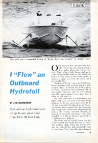
“James Bond’s Weird World of Inventions,” Popular Science, January 1966, pp. 60-63. “Thunderball’s prize piece of gadgetry is a $300,000, 64-foot hydrofoil yacht… production designer Ken Adams couldn’t find a hydrofoil imposing enough for the wide-screen Panavision film, so he decided to build a cocoon aft on a 60-footer, nearly doubling the vessel’s length to an overall 110 feet… The cocoon can be jettisoned at the touch of a button, allowing the hydrofoil to zoom off at full speed. The hydrofoil has a 1320-hp Mercedes-Benz diesel and can hit a top speed of about 40 knots. But Adams can improve on that — by filming it at one-third normal camera speed. Normal projection speed makes the DISCO VOLANTE appear to do over 100 knots.”

Also in this issue, on page 82, is this news blurb with photo: “You can now order the 16′-4″ Larson Volero in hydrofoil-equipped models. so outfitted, the popular stock outboard runabout is capable of speeds topping 45 mph with a 60- or 75-hp motor on her transom. You swing the foils up for normal running by adjusting a hand control in the cockpit near the wheel. The boat is produced in Little Falls MN.” [This hydrofoil version was never produced, according to the Larson company – Editor]

James Bond Inventions in Popular Science January 1966
Brown, Stuart F., “World’s Fastest Sailboat — Two Masts and Three Self-Adjusting Underwater Wings Make For One Rapid Hydrofoil.” Photos by John B. Carnett. Popular Science, Volume 238, Number 1, January 1991. ISSN 0161-7370, Times Mirror Magazines Inc, New York, USA. This issue contains an article on the world sail speed record holding trimaran hydrofoil craft (trifoiler) LONGSHOT designed and built by engineer Greg Ketterman for racer Russell Long. The cover photo by John B. Carnett shows LONGSHOT sailing foilborne in choppy water. A speed of 37.18 knots (42.8 mph) was achieved on Stafford Lake in Lethbridge, Alberta while piloted by Russell Long. At the time, this was the all-out world record for sailboats (100 square foot sail area or more), though even at that time the speed for wind surfers (under 10 square metres of sail area) was significantly higher at 49.4 miles per hour. In the article, Ketterman indicated it should be possible to exceed 50 mph when sailing LONGSHOT in strong steady winds.
World's Fastest Sailboat Article -- Popular Science January 1991
Jackson, William D, Naval Architect, “Build Your Own Hydrofoil Speedboat, ” Science and Mechanics Feb 1960, Craft Print Project No. 304. p.176-179. Plans for building add-on hydrofoils for almost any boat up to 16 feet. The designs are “the result of designing and testing many different types and sizes and shapes of hydrofoils over a period of several years.” Foils are constructed of steel framework with fiberglass foil-shaped lifting surfaces. The next (Apr 1960) issue has plans to build the boat used to test these add-on foils.
Science and Mechanics February 1960
“Jet Hydrofoil Shoots at World Record,” Popular Mechanics, August 1953, pp 70-71. Five B&W photos of Frank and Stella Hanning-Lee’s WHITE HAWK. From the accompanying text: “…two Britishers, Mr. and Mrs. Frank Henning-Lee [sic], aim to break that speedboat record with their jet-powered craft, the WHITE HAWK, on Lake Mead, Nevada, this fall. The man-and-wife team collaborated on the design. Mrs. Henning-Lee [sic] (an American by birth) is the driver… Top speed of the boat to date is 125 miles per hour. But that was loafing along on a stability run in England. when Stella Henning-Lee [sic] opens it up on Lake Mead, she is certain that the speed record… will be held, for the first time, by a woman.”
“Carnival of New, Way Out Watercraft,” Popular Mechanics, July 1963, pp 83 – 85. Among the watercraft depicted are two hydrofoils:

  • FRESH I,”jet-propelled hydrofoil built by Boeing for the Navy has hit 60 mph on Puget Sound, is expected to reach 115 mph with different foils system… the 53-foot flying cat is strictly an experimental craft and will be used to study super-cavitating foil design.”
  • HYDROMARINER, “28-foot cruiser for pleasure market has beam-width surface-piercing foils that retract hydraulically, giving boat docking draft of only 1 foot.”
Cover of Popular Science July 1963
Popular Mechanics September 1967 – An 11.5 ft. one-person hydrofoil developed by Italian designer Rentato Castellani of Verbania can hit 35 mph with an 18-hp outboard engine. The steerable front foil permits tight turns and thrilling acrobatics according to PM. The fiberglass hull is foam-filled and unsinkable, plus it comes apart for easier carrying. The designer intended to sell this craft in kits, but IHS is unaware of any that were sold. Anyone with more information about the fate of this design is encouraged to contact IHS.


Renato Castellani, Popular Mechanics September 1967
Zimmerman, Bob, “The Biggest, Fastest ‘Flying Boat’ Yet!” Popular Mechanics December 1968. Technical art by Fred Wolff. “It’s 212 feet long and displaces 300 tons, but when it goes up on “stilts” it skims across the water — even heavy seas — at better than 40 knots… the PLAINVIEW, made by the Lockheed Aircraft Corp., is the largest hydrofoil ship ever built… it is intended to do the work of a destroyer. A hydrofoil could become the only surface ship that can outrun and outmaneuver a nuclear submarine. It would be large enough to carry sophisticated detection and tracking gear and torpedo launchers. In a foilborne chase, it would be immune to the bouncing and tossing that can interfere with the accuracy of weapons systems in a conventional ship traveling at high speed… Other promising areas are mine warfare, recon missions, amphibious assaults, short-haul transportation of personnel, and oceanography.”
PLAINVIEW, Popular Mechanics December 1968
“Hook’s Hydrofin – Boat Rides on Stilts,” Mechanix Illustrated, Apr 1952, pp. 84-85. “The basic elements are a fuselage (completely out of the water while the boat is in motion), three fins or hydrofoils (under the surface) which are connected to the fuselage by supporting struts or hydropeds, and of course, a power plant. Then, there are two forward projecting stilts, called jockeys, which predict the water surface in front of the foils… Standard Hydrofin production models are 12-1/2, 18-1/2, and 24-1/2 feet long, carrying 2, 5, and 10 people… The manufacturers — Atlantic Hydrofin Corporation of Miami FL… “
Hydrofin Hydrofoil in Mechanix Illustrated April 1952
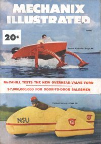
Mechanix Illustrated Nov 1962, HS DENISON — “World’s First Ocean-Going Hydrofoil — New US Wonder Ship To Top 90 Miles an Hour! The HS (Hydrofoil Ship) DENISON, which has flown over the water at 50 knots and which, it is hoped, will do as high as 80 knots (or about 90 mph in landlubber lingo) will be the first operational; ocean-going hydrofoil ship in the world… Development was undertaken jointly by the Maritime Administration and the Grumman Aircraft Engineering Corp. Fifty-seven contractors took part. After a thorough test program to be conducted by Grumman, the ship will be turned over to the Maritime Administration, which will charter it to Grace Lines for use as a passenger ship. Carrying 60 passengers, the DENISON will fly between Florida and the Bahamas.
Denison, Mechanix Illustrated November 1962
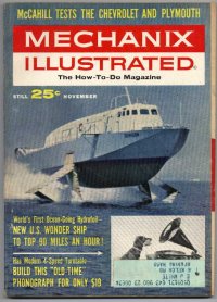
“All about Hydrofoil Craft,” Practical Mechanics, Aug 1961. A survey article of hydrofoil craft in service at the time, in Russia, Switzerland, Italy, Scandinavia, Japan, and South America. From the article: “Until 1959 the Shell Oil Company of Venezuela relied on orthodox high speed launches to carry workers out to the drilling rigs 40 miles off-shore on Lake Maracaibo. Now they have PT 20 hydrofoil boats which carry the same load of 66 passengers at the same speed, on well under half the horsepower… larger PT 50 boats are now working between La Guaira on the Venezuelan coast and Isla de Margharita, 120 miles away in the Caribbean Sea… the River Rhine Police have used hydrofoil launches since 1954… the Suez Canal Authority uses a hydrofoil inspection launch…the Soviet authorities plan to have 285 [hydrofoil boats] in operation on rivers and lakes by 1965… There is of course no possibility of putting ships like the CANBERRA or the QUEEN MARY on foils. The latter would require two million horsepower to make use of them, ten times her present engine room output.”

Granberg, W.J., “America’s First Hydrofoil Ferry,” Mechanix Illustrated, Jul 1961, p.75.  One page consisting of a paragraph of descriptive text and three B&W photos of the FLYING FISH, which operated a ferry route between Bellingham WA and Victoria BC Canada. According to the article, FLYING FISH was a “65-ft., 60-passenger aluminum-hull hydrofoil ferry boat, the first of its type to operate in American waters. Hydraulic controls in the wheel house adjust foil angles for maximum performance under particular weather conditions and at various speeds. The Italian-built craft carried passengers between Italy and Sicily before being purchased and brought to the USA by Dr. Frank A. Colderone of Hempstead NY.”

Mechanix Illustrated, Jan 1959. Contains article on hydrofoil boat design. No details available.

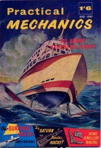
More Hobbyist Magazine Titles (No Photo Available)…

  1. “10′ Hydrofoil Boat or Conversion,” Boat Builder’s Handbook Annual #4, #567 1960 ed, Science and Mechanics – No further details available
  2. “Novel Hydrofoil Cruiser,” Mechanix Illustrated Boating Issue Apr 1956 – No further details available
  3. Popular Science September 1964 – “Big Russian Hydrofoil”
  4. Popular Science August 1963 – “Fast Hydrofoils ‘Fly’ Jet Cat”
  5. Popular Science April 1973
    • 250-Passenger Hydrofoil: “Jumbo Jetfoil Will Be Super-Fast, Super-Smooth,” by Ben Kocivar. pp 76-78, 152. “One of the world’s biggest airplane makers, Boeing, has announced it is going into the boat-building business. The aerospace giant will produce a fleet of 250-passenger, turbine-powered hydrofoils able to cruise in ocean waters at a zippy 50 mph. Boeing already as orders for 11 craft (at $3.5M each) for use in the Hawaiian Islands, Hong Kong, and across the English Channel. Not yet announced by Boeing, but strongly rumored, is domestic service for New York, San Francisco, and other major cities. Boeing forecasts a total market for about 40 of its boats within five years and 100 within 10 years.”
    • “Copter-towed Sea Sled Clears Minefield, ” p. 90. “The Navy’s new Mark 105, an unmanned mine sweeper… is towed by helicopter — up to 80 knots — on four fold-up hydrofoils.”
  6. Walker, Lester C., “Ships That Fly on Wings — Water-transportation Speed Will Triple With Boats That Don’t Float, But Fly,” Popular Mechanics Feb ’61, pp 102 – 105, 268. Good overview of commercial, military, and sport hydrofoils available and planned at the time. Photos of XCH-4, Grumman’s SEA WINGS, FRECCIA DEL SOLE, Grumman’s 15-foot runabout, Gordon Baker’s MONITOR sailing hydrofoil, a Russian Meteor, and some military vessels.
  7. “Aeroplane-Hydroplane Designed by Dr. Bell,” Popular Mechanics, Jan 1920, p. 2. (No further info available)
  8. Popular Mechanics May 1963 – “Squirt Gun on Hydrofoils -Spouting a 30-foot stream of water from a pipe draped over the transom, Boeing’s 2-1/2 ton turbine-powered LITTLE SQUIRT streaked across Seattle’s Lake Washington on an overcast day in January and became the first boat to successfully combine hydrojet propulsion with a fully-submerged foil system. Engineers hope that this one-of-a kind research boat will provide them with valuable information on whether hydrojet propulsion might be used on large, ocean-going hydrofoils. Power transmission, one of the toughest problems in any hydrofoil design, becomes even more difficult in the 100-ton-and-over range. Boeing’s 20-foot Pump Jet incorporates an ingenious solution to the problem.”
  9. “Jet Hydrofoil Shoots at World Record,” Popular Mechanics, August 1953,  pp. 70-71. Short article and 5 photos of Frank and Stella Hanning-Lee and their hydrofoil WHITE HAWK.
  10. Everyday Science & Mechanics September 1932. Contains article on Huge Flying Boat (hydrofoil). No details available.
  11. Modern Mechanics, ???1929, “Racing Over the Water at 100 Miles per Hour!” by Charles Hall.
  12. Quick – The Picture News Magazine, Vol. 1 No. 3 Oct. 28, 1953  “Men: Get Out of the Way!” Triangle Publications Inc., Philadelphia, Penn. Small format bi-monthly magazine, 5 x 7.25 inches, 64 pages – all pictures and no advertising. Include short article with four color photos of the the Hanning-Lee White Hawk – an early hydrofoil speedboat powered by a Rolls Royce Derwent jet engine which incidentally gave it a power/weight ratio of one which would have it allowed it to take off like a rocket if it were pointed skyward. It was piloted by Stella Hanning-Lee and designed by her husband Frank Hanning-Lee, a British experimental boat builder. The color photos include shots of Stella and the boat in action.
History and Classics
Classic Fast Ferries – “the ‘Cyberzine’ about hydrofoils, catamarans, air-cushioned vehicles (ACVs), and other classic fast ferries. This is an on-line magazine in Adobe Acrobat format, free of charge. Current and past issues can all be viewed, printed, and/or downloaded from the Classic Fast Ferry website, editor Tim Timoleon.
Classic Fast Ferries Cyberzine Hydrofoils
“US Navy on Stilts,” Sea Classics, Jan.1974. Has article on Navy PHMs, also “Hydrofoils of the Third Reich.”
US Navy on Stilts (hydrofoils) i n Sea Classics January 1974
von Schertel, Baron Hanns, “Hitler’s Hydrofoils,” The Best of Sea Classics, Summer 1975 and Sea Classics Jan 74, Challenger Publications, Inc. Canoga Park CA, USA, pp 4-9, reprinted from Aviation & Marine Magazine, France. Baron von Schertel first began experimenting with hydrofoil craft in 1927. This article gives details on German hydrofoil development during World War II. In 1939, the military first became interested in a 2.8 ton hydrofoil demonstration boat. Various hydrofoils followed that craft, including the VS 6, VS 8, VS 10, TS-1 Coastal Surveillance Hydrofoil, Single-Seat 3-ton torpedo boat, and the 4-ton Pioneer Corps workboat.
Hitler's Hydrofoils, Best of Sea Classics 1975
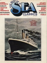
Keene, Tony, “Canada’s Ill-Fated Hydrofoil Sub-Hunter,” Sea Classics, June 1991, vol. 24, No. 6, pp. 46-53. “When built she represented an entirely new and radical form of sub-hunter. But her glory was short-lived and the BRAS D’OR finished her days as an ignoble museum ship… It was the Royal Canadian Navy’s objective to produce an operational vessel, a winged anti-submarine warrior capabile of patrolling the North Atlantic sea lanes. This project, designated FHE-400, resulted in a three-phase contract being signed by de Havilland Aircraft of Canada in 1963, calling for final sea trials and the handing over of the ship to the Royal Canadian Navy by 1969 when it was felt that firm proposals would have to be made to replace the old steam frigates then in service…”
Hydrofoil Submarine Hunter in Sea Classics June 1991

More Classics Magazine Titles (No Photo Available)…

  1. Sea Classics, January 1983, “New Navy Hydrofoils — Two Experimental Gunboats Prove Themselves and Then Some in Harsh Tests”. No details available.
Ferries and Other Commercial Ships and Craft
Hovering Craft and Hydrofoil, Volume 18, Number 7, April 1979. The International Review of Air Cushion Vehicles and Hydrofoils. Was published monthly by Kalerghi Publications, London. The magazine was later published as High-Speed Surface Craft and is currently released under the title Fast Ferry International. The cover of this issue features an artist’s impression of HMS SPEEDY by Boeing Marine Systems. HMS SPEEDY was a derivative of the Jetfoil series of passenger hydrofoils and was evaluated for a period of time by the Royal Navy. Inside the issue is a six page article on this hydrofoil by Antony Preston which includes photos of HMS SPEEDY under construction at the Boeing factory in Seattle and a number of sketches of the propulsion and control systems.
Hovering Craft and Hydrofoil April 1979 Features HMS Speedy
High-Speed Surface Craft Incorporating Hovering Craft and Hydrofoil, October 1982, Vol. 21, No. 10. Published by Capstan Publishing Company Ltd, Surry, UK. This journal was previously published as Hovering Craft and Hydrofoil and subsequently became Fast Ferry International. While the cover of this particular issue features a high speed catamaran by Cougar Marine, it contains several articles on hydrofoil themes including: International Hydrofoil Society North American Association First Conference; Current status and future prospects for US commercial hydrofoils; Current status and future prospects for Far East commercial hydrofoils; The evolution of the NIBBIO class hydrofoil from TUCUMCARI; Reconstruction of the HD-4 hydrofoil; Unhappy debut for new Jetfoil service; and History of US involvement in developing the hydrofoil (part 3).
Hydrofoil Articles in High Speed Surface Craft Magazine
Pierless Magazine, Future Ferries, The Final Frontier, April 2000. Includes article on Ultra-fast hydrofoil ferry proposed by Hydrofoils Inc.
future hydrofoil ferries in Pierless magazine
Fairplay International Shipping Weekly, Vol 274, No. 5052, 26 June 1980. Published weekly by Fairplay Publications Ltd, London. This issue features a cover photo of Boeing Jetfoil 929-115 CU na MARA, which was with B+I on a Liverpool to Dublin run at the time. The issue features a two page article by Michael Hood examining two Jetfoil services.
Jetfoil Article in Fairplay Shipping Weekly
“Hitachi Zosen News” Volume 5, Number 6 of August 1962 (also apparently issue 30). The blurb about the front cover states: “The Port of Takamatsu on Shikoku Island is one of the key ports of marine traffic on the inland sea of Japan. In the photo is shown the hydrofoil boat (constructed by our company) connecting the Osaka and Kobe districts with Port Takamatsu.” Click Here for a close up of the PT-20 in the photo.
Cover of Hitachi Zosen News August 1962 with hydrofoil
Ship and Boat International, Issue 96/1, January/February 1996. Published ten times a year by The Royal Institution of Naval Architects, London, UK. The cover of this issue features the second commercial example of the Kvaerner Fjellstrand FoilCat, Barca, which at the time of publication had entered service between Hong Kong and Macau with Far East Hydrofoils. The 35 metre foil supported aluminium catamaran is powered by a pair of 4485 kW GE LM500 gas turbines driving KaMeWa 80S11 waterjets through MAAG gearboxes. The craft can carry 403 passengers. While a speed of 52 knots was achieved on trials, the normal service speed is about 45 knots. This issue includes a short one third of a page article on the FoilCats. The journal from time to time features other hydrofoil production news.
cover of Ship & Boat International with Foilcat hydrofoil
Speed at Sea, The Journal for Fast Ship Operators, Volume 7, Issue 3, June 2001. ISSN 1359-4222. This Journal is published six times a year by Speed at Sea Publishing, Enfield, UK. From time to time, items related to hydrofoils or hydrofoil-assisted craft will appear in the journal. The June 2001 issue for example features a three-page review of the 54.5m hydrofoil-assisted trimaran TRIUMPHANT built by North West Bay Ships in Tasmania, Australia. The trimaran is equipped with a Maritime Dynamics, Inc. lift and ride control system for which the lifting surfaces consist of a pair of hydraulically actuated foils between the main hull and side hulls as well as trim tabs aft on the centre hull. The foils not only improve the motions of the vessel in waves, but additionally provide lift thereby enhancing the overall performance of the ship.
Cover of Speed at Sea with hydrofoil trimaran
Work Boat World, Volume 21, Number 7, October 2002. ISSN 1037-3748. This Journal is published twelve times a year by Baird Publications Ltd, Hong Kong. As with other such journals, items will occasionally feature hydrofoils or hydrofoil-assisted craft. The October 2002 issue features a one-page review of the 40.2m hydrofoil-assisted catamaran ‘Linda’ built by Almaz Marine yard in St. Petersburg, Russia. The catamaran is equipped with a pair of bow foils and the sterns of the demi-hulls support the remaining weight and incorporate a pair of waterjets.

More Commercial Hydrofoil Magazine Titles (No Photo Available)…

  1.  “SeaFlite Jetfoil — The Boat That Thinks It’s a Plane,” Flying Colors, (Braniff Inflight Entertainment Magazine) Vol 6 No. 1 1977
  2. 1st Annual Encyclopedia of Vertical Lift Craft, June 1967, Vertical World . A magazine of Helicopters, V/Stols, ACV’s, Hydrofoils. Approx. 11 1/4″ x 8 1/4″. 98 pages.
  3. Sealink News, Edition 34, September 1981, “The House Magazine for staff of Sealink UK Limited.” Feature ship is the RMT Dover – Ostend Boeing Jetfoil Princesse Clementine – full color centerspread with technical details and reports on her introduction.
Military Hydrofoils
Air West 1968 Tucumcari Article With Photos
Air West Magazine, 1968 50th Issue
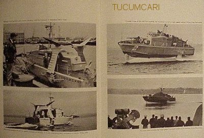
Shethar, Alan, “Wings Upon the Water: The Hydrofoil,” All Hands, The US Navy Bureau of Personnel Career Publication, Jul 73, pp2-7. Photos and text descriptions of PHMs, AGEH-1 PLAINVIEW, PCH-1 HIGH POINT, and PGH-2 TUCUMCARI
All Hands Magazine July 1973
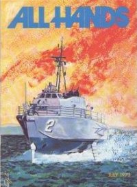
Christy, John, “Punch-Packing Sea Skimmers,” International Combat Arms, May 1985, Vol. 3, No. 3, Petersen Publishing Co., Los Angeles CA 90069, pp 39, 68 – 74. Lots of good photos. From the text: “…by the time the NNAG studies, with input from as many as 11 navies, were completed and the three signatories to the “Memorandum of Understanding,” the U.S., Italy, and the Federal Republic of Germany, had completed the signing, the size of the projected vessel had doubled. With all the performance factors cranked into the equation, and all the machinery and weapons added, the 74-foot prototype design had grown to 130 feet with a hullborne tonnage of 224 tones (39.5 meters and 228 tonnes). Cost factors were commensurate with the increase in size, and by 1974, Ital and the FRG had opted out, leaving the U.S. and Boeing to go it alone. The Italians downscaled their requirements and made a license agreement with Boeing to use the original TUCUMCARI design, modified for missile use, and the Germans decided on the Luerssen S 143 hullborne FPB…”
PHM Program Review in Combat Arms magazine
Naval Engineers Journal, Volume 95, Number 5, September 1983. ISSN 0028-1425. Published by the American Society of Naval Engineers, Inc. (ASNE). This issue features a cover photo with all six PEGASUS class PHMs flying together for the first time in US Navy history. The mission took place off Key West, Florida, where all the hydrofoils were stationed. Photo was provided courtesy of William M. Ellsworth and PHM Squadron 2 based in Key West. The caption for the photo also indicated that it would be unlikely that all six hydrofoils would operate together again, as some would be rotating through shipyard cycles. The Naval Engineers Journal from time to time has included technical articles related to naval hydrofoil design.
PHM Formation on cover of Naval Engineers Journal September 1983
Naval Engineers Journal, Volume 97, Number 2, February 1985. ISSN 0028-1425. Published by the American Society of Naval Engineers, Inc. (ASNE). This special edition features comprehensive reviews of a range of ‘advanced naval vehicles’, including hydrofoils, Surface Effect Ships (SES), Wing-in-Ground Effect (WIG) craft, Air Cushion Vehicles (ACV), Small Waterplane Area Twin Hulls (SWATH), planing hulls, and modern monohulls. This is an ideal source of background information in considering the merits of different craft types for particular roles.
Naval Engineers Journal February 1985
Naval Forces, Vol.VI, No.2, 1985. Published by Monch Publishing Group. Features cover photograph showing the USS Hercules. Although this issue does not contain an article on the PHM class, the journal does deal with naval hydrofoils from time to time. The blurb for the cover photo states: “The USS HERCULES (PHM 2), one of the six patrol hydrofoil missile craft which were built by Boeing Marine Systems in Seattle, Washington. They are currently operational with the US Navy in the Caribbean with PHM Squadron 2, at Key West, Florida. The squadron became operational in 1983. These craft are capable of over 40 knots and are armed with eight Harpoon missiles, one Oto Melara 76 mm gun and Mk 92 fire control system. This issue does contain one small black and white photo of a Chinese Huchuan class hydrofoil torpedo boat as part of an article on the Chinese navy (Hu Chwan is an alternate spelling for this boat class; it means White Swan).
PHM-2 on cover of Naval forces magazine
Copeland, Earl Jr., “Hydrofoils,” National Defense, Mar-Apr 1970, Vol. LIX, No. 329, published by the American Defense Preparedness Association, Washington DC. pp 382 – 386. Survey of the state of the art for hydrofoils at the time of publication. Discussion and photos of PHM-1 PEGASUS, FLAGSTAFF and SUPER FLAGSTAFF (concept), DENISON, PLAINVIEW, HIGH POINT, Philippine Navy Patrol Craft, H-890, RHS-140 ferry, Italy’s SWORDFISH and PAT 20, seagoing PT-150, PT-50 BALSA SEAWING, Seaflight L90 ferry, Canada’s BRAS D’OR, and TUCUMCARI. Discussion without photos of BUREVESTNIK, BYELORUS, CHAIKA, CYCLONE, DELPHIN, LUCH (Ray), MIR, NEVKA, STRELA,  Kometa, Meteor, Pchela (Bee), Raketa, Sputnik, Typhoon, Nikhr (Whirlwind), Volga, Molnia
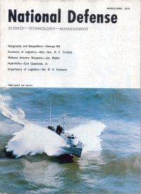
“Israel’s Hydrofoils,” Defense Update International, Born in Battle, No 66, 1985. No further info available.
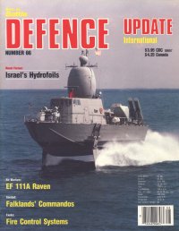
International Defense Review, Volume 16 No. October 1983. ISSN 0020-6512 (SZ), Monthly journal published by Interavia S.A., Geneva, Switzerland. In English, French, German and Spanish editions. This issue features a cover photo with the Italian Navy hydrofoils ASTORE and GRIFONE, two of a class of 60t hydrofoils built by CNR. A four page article on the Nibbio class is presented in the issue which was prepared following the delivery of the sixth and final vessel of the Italian navy. Also see Vol 4, No. 6, December 1971 of this magazine for an article on military hydrofoils.
International Defense Review October 1983
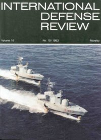
Firepower – The Weapons the Professionals Use – and How. Published weekly by Orbis Publishing Limited / Aerospace Publishing Ltd, London, 1990. Volume 3, Issue 33 features the US Navy’s PEGASUS class hydrofoil HERCULES (PHM 3) on the cover and provides the general particulars of that class and other dynamically supported and conventional fast attack craft in its contents. 23 pages of text and photos.
Firepower Magazine 1990 Volume 3, Issue 33
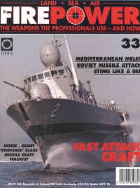
Navy International, Vol. 78, No. 11, November 1973. Published by Maritime World Ltd, Surrey, UK. This issue features the Italian Navy hydrofoil SWORDFISH (P 420) on the cover and a four page article of the Nibbio class hydrofoil following sea trials of the first of the class. There is also a five page article of the US Navy’s Surface Effect Ship program in this issue.
Navy International Magazine November 1973
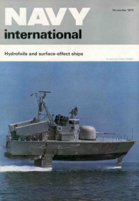
Zimm, LCDR Alan D., US Navy, “PHMs: Unique Ships, Unique Problems, Proceedings, Volume 108/2/948 February 1982, pp 90-93. Proceedings is published monthly by the US Naval Institute, Annapolis, MD, USA. ISSN 0041-798X. The cover of this issue features USS TAURUS (PHM-3) taking a tight turn during tests at Puget Sound. The article in this issue deals with the complexities of how to manage the PHM in the USN fleet and the need for doctrine and tactics to suit the unique characteristics of the class. The article responds in part to an earlier article by LCDR Linder entitled “PEGASUS: Winner or Also-Ran?” published in the Sep 1981 issue of Proceedings .The well known aerial photo of a PHM executing a “Figure 8” is captioned, “Is the PHM here demonstrating the maneuverability of the ship or the direction of the PHM program?”
U.S. Naval Institure Proceedings February 1982
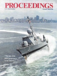
Jane’s Defence Weekly, Volume 2, Number 7, 19 August 1989. As the title suggests, JDW is a weekly defence journal. From time to time, items concerning naval hydrofoils will appear in the weekly. This particular issue features a cover photo with an Italian Navy Sparviero class (also known as Nibbio class) hydrofoil, and subtitle ‘Japan opts for Italian hydrofoils’. A half page article by Kensuke Ebata in Tokyo notes that the Japanese Defence Agency has requested three Italian Sparviero class hydrofoil missile boats for its Maritime Self Defence Force in its FY90 budget. The hydrofoils were to be built under license in Japan.
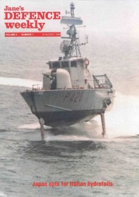
Jane's Defence Weekly August 1989
HIGH POINT Joins the Navy,” Undersea Technology, Nov 1963, Vol. 4, No. 11, Compass Publications, Inc. Arlington VA 22209, p.23. Introductory text and four B&W photos. From the text: “The new hydrofoil craft HIGH POINT , has entered the service as the Navy’s first operational hydrofoil craft. Largest hydrofoil in the Nation, she’s currently undergoing extensive testing at Puget Sound, Washington. The 110-ton ship, designed by the Navy’s Bureau of Ships and built by the Boeing Company, will soon head south to join the Pacific Fleet… armament on the HIGH POINT  consists of four MK 32 torpedo tubes, two on each side, and a .50 cal. machine gun mounted just forward of the pilot house.”
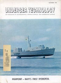
Farther, Spring 1987 (Vol. 2, No. 1) PHM-1 USS PEGASUS cover. Article about PEGASUS. Back in the 1980s, Electronic Arts published a magazine that was sent to people that registered their software.  These magazines featured game news and interviews with the creators. It’s not just marketing hype – there’s some good content also. No further (Farther!) information available.

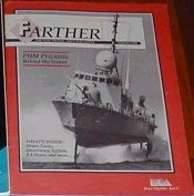
More Military Magazine Titles (No Photo Available)…

  1. Aviation Week and Space Technology 22 Feb 60 contains an industry survey of hydrofoils. No further info available.
  2. Pacific Defence Reporter Aug 1981, “The Hydrofoil As a Weapon,” by Ian Hamilton. “The hydrofoil, with a capability of speeds close to 160 km/h, clearly has both offensive and defensive capabilities… The first hydrofoil boat was the product of an accident in 1861, when Thomas Moy, an Englishman, decided to study the aerodynamics of wings by observing the underwater swirls they created. Having attached wings to his craft, he ventured out onto the Surrey Canal. To his surprise, the ship rose from the water — and unintentionally he had invented hydrofoils. But it was not until 1898 that the first efficient hydrofoil was designed by Enrico Forlanini of Milan…”
  3. Warship International Nov 4, 1975, Vol XII No. 4, published by the Naval Records Club (later became the International Naval Research Organization –INRO — which now publishes Warship International), “New Addition to the Fleet: Pegasus (PHM-1) Missile-carrying Hydrofoil Ship” (1 page with photo).
  4. Our Navy Magazine Vol. 58, No. 2, February, 1963, “The Future for Hydrofoils.” No details available
  5. Sea Combat, August 1978, Contains article on USS PEGASUS (PHM-1) hydrofoil missile ship.
  6. 1st Annual Encyclopedia of Vertical Lift Craft, June 1967, Vertical World . A magazine of Helicopters, V/Stols, ACV’s, Hydrofoils. Approx. 11 1/4″ x 8 1/4″. 98 pages.
  7. Naval Record Vol. III, No. 4, Jul/Aug 1968, Monitor Publications London, p. 65. Two small Boeing B&W photos, one of PGH-2 TUCUMCARI, the other of PCH-1 HIGH POINT. The caption reads, “The [HIGH POINT] is fitted for anti-submarine duties and is armed with twin fixed tubes (angled from the centreline) for A/S torpedoes on each side amidships, a 40mm gun forward, and with VDS at the stern; while the [TUCUMCARI] is armed as a gunboat with a 40mm gun forward, an 81mm mortar aft, and twin .5 inch guns abaft the bridge. Both craft have amply demonstrated their seaworthiness and manoeuvrability in rough weather trials of the West Coast, and have retractable foils for operating in the displacement mode.”
Yachts, Sailboats, and Motorboats
Multihulls Magazine, Volume 25, Number 3, May/June 1999. ISSN 0749-4122. www.multihullsmag.com e-mail: multimag@aol.com Editor: Charles K. Chiodi. The magazine is published bimonthly and from time to time may feature articles concerning hydrofoil-supported multihull sailboats. This issue includes a two-page article with photo by Dave Carlson titled “Foiling with one of the Giants”. The article describes Dave Carlson’s experience with working on and sailing a foil-supported Hobie 18 designed by the late Dave Keiper. For updates on Dave Carlson’s continued work with foil kits in Gainesville FL, visit his website or contact him by email.
Multihulls Magazine May/June 1999
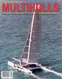
Multihulls Magazine, May/June 1990 Issue. Cover illustration is of the Hobie TRIFOILER
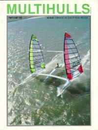
Multihull World Magazine – Power and Sail, Number 47. ISSN 1034-5108. www.multihull.com.au / email: info@multihull.com.au. Editor: Paul Lynch, P&G Lynch and Associates. Issue 47, published early in 2000 features a cover with an artist’s impression of the VOLANTIS designed and to be built by HydroWing Hawaii. The four page article on this design includes a three view drawing of this 60 foot hydrofoil sailing vessel. The design has been co-developed by Sam Bradfield (hydrofoils), David Hubbard (sails) and Nigel Irens (hull). The goals of the VOLANTIS are described as “to capture the world’s speed record for sail powered craft, to break the world’s 24 hour distance record for sailing and to set new course records for open ocean races worldwide.” Other articles on VOLANTIS have been published in Seahorse Magazine (Nov.2000), Multihulls Magazine (Mar/Apr 2000), Composites Fabrication (March 2000), Canadian Yachting Magazine (Regatta 2000), and Yachting World (July[??] 2000).
Multihull World Magazine Issue 97
Yachting, April 1929. Contains article on 30-foot hydrofoil, text and photos. No other information available. If anyone can provided a photocopy to IHS, it will be greatly appreciated. Contact the webmaster@foils.org.
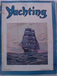
Vincent, R. E., “Beware Low Flying Boats — An Experimental Hydrofoil Craft With an Ingenious Theory for Stability,” Yachting World, May 1972, pp 98-99, IPC Transport Press Ltd, London, publishers. Article by a post-grad student. Paragraph headings are: Design Objective, Apparent Wind Analysis, Propulsion Device, Transverse Stability, Longitudinal and Directional Stability, Resultant Overall Design, Predictions of Future Developments, and Conclusion.

“Offshore at 40 knots,” Yachting World May 1998, pp 16-19. No details available.

Yachting World International, May 2002, Volume 154, Issue no. 3125. For more information on this magazine see www.yachting-world.com . This issue features the French sailing hydrofoil L’HYDROPTERE on the cover. The issue has 26 pages of content on the theme of “Greed for Speed”. Articles include “Speed Pioneers” tracing the history of speed sailing at the Portland Speed Week prepared by David Pelly, “Offshore record breakers” by James Boyd, “Breaking the 50-knot barrier?” by Matthew Sheahan, and “Pushing the Boundaries” by Elaine Bunting. There are nice photographs of the hydrofoil catamarans Spitfire, Techniques Avancees, Mayfly and Icarus, the small hydrofoil trimarans FORCE 8 and LONGSHOT, and the hydrofoil-supported trimarans PAUL RICARD and L’HYDROPTERE along with other fast sailing craft.
Johnston, Robert J., “Hydrofoils, Ships That Fly,” The Rudder, the Magazine for Yachtsman, The Rudder Publishing Co., 9 Murray St, NewYork 7, NY, Nov 1953, Vol. 69 No. 11, pp 30 – 33. Included 9 small B&W photos. Bob Johnston wrote this article as a Lieutenant Commander in the US Navy, serving as Hydrofoil Project Officer for the Mechanics Branch of the Office of Naval Research (ONR). The article traces the history of hydrofoil development through the contemporary date in 1953. Among the hydrofoils described are:

  • CAPT H. C. Richardson’s hydrofoil canoe (1908) and hydrofoil dinghy (with collaboration of N. White)
  • A. Guidoni’s application of hydrofoils to seaplanes in Italy (1911)
  • Alexander Graham Bell’s HD-4 (with assistance of Casey Baldwin and Philip L. Rhodes) (1919)
  • L.P. Coombs and E.T.J. Davies experiments in England with hydrofoils on seaplanes (1930s)
  • W. Grunberg of France – his patent for automatically adjusting the foil angle of attack (1938)
  • Sachsenberg brothers and Dr. O. Tietjiens experimental hydrofoils
  • German hydrofoils in the World War II era
  • J. G. Baker’s hydrofoil sailboat Monitor
  • Christopher Hook’s Hydrofin
  • William P. Carl’s hydrofoil research
  • The Hanning-Lee’s White Hawk
Carl, William P., “The Fantastic Hydrofoil Runabout – Its Development and Future,” The Rudder, Aug 1958 – How SEA WINGS hydrofoils developed from bathtub hobby to commercial reality. “This story begins in 1938, in Bob Gilruth’s bathroom… he started with 6-inch models…from the model tests, a full scale, 12-foot sailing catamaran with hydrofoils, CATAFOIL I was built and operated in the Chesapeake for several years.” The author started a collaboration with Bob Gilruth in 1943 that led to to world’s fastest open sea waterborne vehicle — the XCH-4. But the US Navy turned down the idea of an 80 knot patrol boat, so the author turned to commercial products. In October 1955 he tested SYNOTROPUSS, an 8-foot rowboat with fiberglass foils and 7 hp outboard that made speeds over 30 mph. The next test craft was a 16-ft Goodyear family runabout fitted with foils that could do 34-mph. In August 1956, the author associated himself with Grumman Aircraft engineering Corp. After months of testing a foil-equipped 15-ft aluminum runabout in Florida, the Grumman boat was placed on the market at the New York Boat Show, January 1957. Unfortunately, “there were so many man-hours of labor involved in production it put the cost out of reach of the mass market.” At the time this article was written, a new type of mount had been developed to allow the Sea Wing foils to be attached to many makes of 14- to 16-ft runabouts.
Hydrofoil Runabout, Rudder Magazine August 1958

  • “Hydrofoils – What the Future Holds,” Motor Boating, Sep 1962 (see photos). No further details available
  • “Foilborne Ferry Approved by Coast Guard,” Motor Boating, Feb 1963. No further details available.
  • Mitchell, James E. “The Commutaboat Hydrofoil: A Passenger Hydrofoil Boat Demonstrated at Oyster Bay,” Motor Boating, Feb 1963, pp 38-39, 101, 103 . “Except for ‘eyes’ staring from her bow, which turned out to be two powerful headlights, and for the shark’s mouth painted across it, she could have been an ordinary 22-foot outboard cruiser. On the pier, waiting to greet us were the three men who had been instrumental in bringing this controversial craft to our shores: John P. Humes, Robert C. Morrell, and C. Maxwell Carver, president and vice-presidents respectively of Commutaboat, Inc.. The corporation was formed with the option to manufacture in the US all hydrofoil designs produced by International Aquavion, Ltd. of London… And sometime in 1963 they will begin to appear on the market with a price tag of around #15,000.”
  • “Hydrofoil Sailboats,” Motor Boating, Jun 1955. No further details available.
  • “Hydrofoils,” Motor Boating, Apr 1950. No further details available


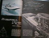
Joseph, James, “Wings for Your Boat; The Astonishing Story of Hydrofoils, Powerboat Oct 1960, pp 8-13, 68-69. Explanation of how hydrofoils work and a nice survey of existing and planned hydrofoils for pleasure, commercial, and military uses. The vessels depicted in the article’s 15 photos are Midwest Hydrofofin Co.’s foil kit (featuring the Christopher Hook concept of “wave-sensing skids which ride in front of boat”), Evinrude Motors’ dreamboat JETSTREAM by designer Brooks Stevens, Baker Manufacturing’s experimental Navy craft HIGH POCKETS with tandem surface-piercing foils, Rodrigues passenger boats operating in the Mediterranean, the XCH-4 designed for the Navy by William P. Carl with seaplane hull supported by two sets of foils forward and a single strut and foil aft, a Grumman concept passenger craft designed for the US Maritime Administration, two workboat models (one numbered MA-2133), and HALOBATES, a gas-turbine powered converted LCVP.

More Yachts, Sailboats, and Motorboats Titles (No Photo Available)…

  1. The Rudder Magazine, Oct 1911. Hydrofoil article; no copy or details available.
  2. Pacific Motor Boat September 1932 “Hydrofoils to Increase Boat Speed.” Article is about Dr. Oskar G. Tietjens, special engineer of the Westinghouse Electric and Manufacturing Company. Describes testing of HYDRO-SKIPPER model on the Delaware River
  3. Brennan, Walter X., “The Newest Hydrofoil Boat,” Yachting, Jan 1936, pp. 55 & 88. Contemporary news and background on the U.S. 3 hydrofoil racing boat (incl. 3 small B&W photos). Excerpts from the article: “The launching and first trials at Detroit of the new Evans hydrofoil boat aroused considerable interest in the subject… The hull, which was designed by P. L. Rhodes with F. W. (Casey) Baldwin as consultant, and built by John L. Hacker, is double planked and is extremely light… The weight of the entire hull is said not to exceed 850 pounds… A Packard Gold Cup motor is used, and aeronautical engineers who are working on the boat estimate a speed of over 150 miles per hour… Using the data they obtain in tests, they plan to build a larger boat with 50 percent more power if the plan appears practicable… More tests are to be made in Detroit waters until it becomes too cold, when the boat will be shipped to Florida for further experiments.”
  4. Boats Magazine, Apr 1955, “Running Trials on a Hydrofoil Boat”
  5. Mallery, Craig, “Boats With Water Wings — The New Hydrofoils,” True, The Man’s Magazine, Boating Yearbook, No. 3 1958. Includes description and photos of the Hook HYDROFIN by Christopher Hook, Grumman 15-ft. Runabout with Sea Wings (a US$595.00 option), and WATER HAZARD (“Hap Hazard sells plans for his hydrofoil system as well as aluminum extrusions for building the foils themselves.”) According to the article the Sea Wings foils were constructed of fiberglass and epoxy resin, mounted with metal retractable hinges.
  6. Power Boat May 1962, “New Hydrofoil Boat Makes Debut” (no details available)
  7. Miller, R.T., Commander, U.S. Navy, “Hydrofoil Craft”, Yachting March 1955, pp. 58-60, 127. Good overview of hydrofoil craft at the time, mostly engine-powered craft. Source of historical and technical data for the article was a paper “An Appraisal of Hydrofoil Supported Craft,” presented at the Annual Meeting of the Society of naval Architects and marine Engineers (SNAME) in Nov 1953 by LCDR P.N. Leehey, USN and CDR J.J. Stilwell, USN.
  8. Carl, William P., “Hydrofoils — The Story Behind the Wings Which Operate in Water,” Yachting March and April 1958 issues.
  9. Drake, Elliot, “Latest Look in Hydrofoils: For a New Experience in ‘Flying’ — Fit Your Boat With Hydrofoils,” Yachting, [exact issue unknown] 1960, p.94, 180 – ?. Four pages of descriptive text and several b&w photos showing details of the Sea Wings hydrofoil kit by William Carl’s Dynamic Developments, Inc. This is a follow-up to the William Carl article on the same subject published in the March and April 1958 issues of Yachting. From the text of this article: “Until now, to fly over the water on Sea Wings, you had to buy a complete 14′-6″ Grumman aluminum runabout with foils attached. The outlay started at $1595. This left others who already owned boats too far away from…”
  10. 1st Annual Encyclopedia of Vertical Lift Craft, June 1967, Vertical World . A magazine of Helicopters, V/Stols, ACV’s, Hydrofoils. Approx. 11 1/4″ x 8 1/4″. 98 pages.
Models – Display and Radio-Controlled (R/C)
Johnson, Frank, “1/32 Scale German VS8 Hydrofoil,” Scale Ship Modeler, Jul 82, Vol. 5, No. 4, Challenge Publications, Inc., Canoga Park CA 91304, pp 44 – 49, 57-59. The article is about the kit offered by 32nd Parallel Corp, now defunct, and is a must for anyone with this kit. The article includes 11 generously-large photos, of which 4 are in color. The text is historical information, description of the kit and of 32nd Parallel Corp. There is nothing in the way of detailed tips based on experience as to how to assemble or operate the kit (note: the IHS correspondence archives on R/C models contain discussion of operating problems and possible solutions). The author is formerly of the staff of Sea Classics Magazine. From the text: “…the VS-8 was a magnificent machine, beautiful in every respect and highly advanced for its time. Aside from the fact that the prototype’s 103-foot length made it the perfect size for 1/32 scale modeling (producing a 38.5 inch hull), it would also be the first hydrofoil (not to mention the first scale hydrofoil) ever offered in an operational R/C construction kit.”
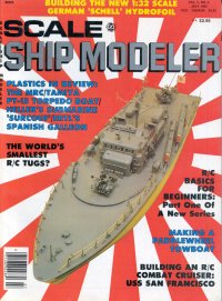
Marine Modelling International – Plans and Construction Guide, 1998, Traplet Publications Ltd, Worcestershire, England. This guide features the RAPIER hydrofoil model (plan number MAR2392) designed and constructed by Graham Taylor on the front cover. There is also a photo and brief description of this 950mm long model designed for up to .40 sized internal combustion engines in the guide, but further details are contained in the December 1992 issue of the Marine Modeling Monthly magazine. See also “Wings Under Water; Graham Taylor Discusses Model Hydrofoils”, Marine Modeling Monthly, August 1991. For further details and photos of Graham Taylor’s two neat hydrofoil models, see his website. Here are citations taken from the site:

  • “Wings Under Water,” Marine Modeling Monthly, Aug 1991: Illustrated discussion introducing hydrofoil principles and model subject potential. 903 words 7 illustrations.
  • “Experimental Hydrofoil,” Marine Modeling Monthly, Jan 1992: Fully illustrated article outlining hydrofoil concepts and describing the design, building and experience gained from MK 1, an experimental 42ins long powered model designed by the author. 1616 words 13 illustrations.
  • “RAPIER Model Hydrofoil Boat,” Marine Modeling Monthly, Dec 1992: Full plans, assembly details, illustrations and instructions for construction of 37ins long glow-plug engine powered radio controlled hydrofoil model designed by the author. Model featured automatic adjustment of foil incidences to achieve tight banked turns. RAPIER plans now held by Marine Modeling Monthly plans library service, plans reference no: MAR2392. 2300 words 11 illustrations.
  • “Foiled Again!” Marine Modeling Monthly, Dec 1993: Illustrated article discussing latest developments in hydrofoil technology. 805 words 11 illustrations.
Marine Modeling Plans and Construction Guide 1968
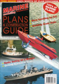
Model Boats, Vol.47, No.558, 27 June 1997. ISSN 00819-8277. Published by Nexus Special Interests Limited, UK. Features a four page article with 13 photos and a small arrangement drawing of the Zytiron 24 model racing hydrofoil produced by Hydrofoils, Inc. This model is no longer produced.

(not shown) Model Maker & Model Boats, Jan 1966, “The British monthly journal for all model makers,” includes an article on Japanese hydrofoil models. No details available.

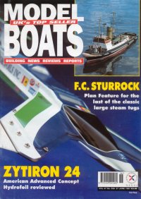
Bruce, Ian, “Hydrofoil Craft,” Meccano Magazine, Oct 59, Vol XLIV No. 10, pp 427 – 429, published in Liverpool England. Discussion of hydrofoil craft of the time, history, advantages over conventional craft, and explanation of how hydrofoils work. Photos of the first Saunders-Roe R-103 BRAS D’OR (re-named BADDECK in 1962 in anticipation of the construction of the larger FHE-400 which was to be given the name BRAS D’OR) and a Supramar PT-20. There is no information in the article about how to model the vessels discussed. From the text of the article: “.Compared to other types of speedboats of equal size, hydrofoil boats possess many important advantages. For instance, only half the engine power is required to attain the same speed. Fuel consumption is reduced by as much as half, and consequently the cruising range is nearly doubled. Economy in fuel, as well as the possibility of covering an increased daily distance as a result of much higher speeds, results in in a reduction of about 30 percent in operating costs.”
Gue, Frank, “Hydrofoils, a new dimension,” Radio Control Modeler, published by R/C Modeler Corp., 120 W. Sierra Madre Blvd; Sierra Madre CA 91024. Vol. 17 No. 5, May 1980, ISSN 0033-6866, pp. 72, 82, 84, 86-87, 90. Includes one line drawing and two small B&W photos. The author describes his successful experiments with hydrofoil landing gear on a 60″, .19-powered model airplane test bed. He created a series of model planes, logging over 1,500 flights at the time of the article. The article includes many tips on design, waterproofing, and operation. Quotes from the article: “A hydrofoil, fitted to an aircraft, lifts the immersed parts clear of the water so that displacement drag is eliminated. It also cures the glassy water syndrome, which can literally prevent respectable airplanes from taking off at all. The famous Canso patrol flying boat was subject to this… wavelets of two or three inches (scale height of more than one foot) don’t bother the model at all. On long swells, it glues down beautifully  while planing, thanks to its tricycle configuration until flying speed is reached, at which time it generally launches itself spontaneously for the top of the first swell over which it has airspeed…. Flying off hydrofoils is truly a new dimension to this marvelous hobby of ours. Try it! You’ll like it!”
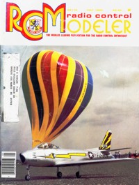
Radio Control Boat Modeler, Vol.10, No.2, February 1996. ISSN 1043-8009. Published seven times a year by Air Age, Inc, Wilton CT, USA. Features a three page articles with photos of a 24-inch long fast electric hydrofoil model produced by Hydrofoils, Inc. This model is no longer produced.
Musciano, Walter A., “von Schertel’s VS-6 Hydrofoil Patrol Boat,” Young Men (formerly Air Trails Hobbies for Young Men) Nov 1955 Vol. 45 No. 2, Street & Smith Publications, Inc., New York. pp 34-35, 86. Article contains parts list, cutaway illustration, exploded view of structure assembly, and teensie-weensie plan (the full size plans were available by mail order for 50 cents: Hobby Helpers Plan #1155). The article explains a bit of hydrofoil history. An experienced modeler who wanted to model the VS-6 would find this article helpful, but the plan is tiny and short on dimensions. Too bad Hobby Helpers went out of business years ago. Some of their plans for model aircraft have been preserved and copied onto modern drafting media for sale, but it is unlikely the hydrofoil plan is available anywhere. The Hobby Helpers plans were printed on cheap paper, not designed to endure over many years.

Air Trails Hobbies for Young Men, July 1955, has plans for a for “Water Warrior” hydrofoil.  No further info available.

More Model Magazine Titles (No Photo Available)…

  1. Air Trails Hobbies for Young Men, July 1955, has plans for a for “Water Warrior” hydrofoil, and the Nov 1955 issue has an article on a von Schertel VS-6 hydrofoil patrol boat. No further info available.
  2. Gue, Frank, “Hydrofoils,” Model Airplane News, July 1974, pp. 50, 64. Air Age, Inc. White Plains NY. “Having trouble getting that waterbird of yours to unstick? If so, why not try hydrofoils [seplane landing gear] as suggested here!” Article includes sketch and instructions for adding hydrofoils to model seaplanes. The example used is a Navigator flying boat kit by C.A.Zaic Co; however enough specific information is given to allow addition of hydrofoils to most seaplanes, allowing for experimentation to optimize the exact location and size of the foils. From the article: “Too small a hydrofoil will not have the desired effect. Too large a hydrofoil will result in hull lift at so low a speed that the flying surfaces have no control, resulting in excessive pitching and pounding over wavelets… The hydrofoil should be far enough ahead of the center of gravity that its force vector lies ahead of the C.G. and exerts a slight nose-up couple. It should be far enough below the hull that interference is minimized and that the hull can be fully clear of the surface when the hydrofoil is still submerged. If the foil is too far forward, the aircraft will lift nose-high and plow rather than plane, throwing spray into the prop. If too far aft, of course, it will force the nose down. Foil incidence should be moderate: 4 deg. to 6 deg. to the waterline seems OK…”
  3. Model Ship Builder March/April 1999 No. 188, pp 41 – 50, “Building the Bell-Baldwin Hydrofoil HD-4,” by Dave Acker. This article was reprinted in its entirety as a special extra edition of the IHS Newsletter in Summer 2000. Equal mix of fascinating history and instructions for building a detailed scale model. Lots of photos. “As a prelude it should be known that the hull/fuselage of the HD-4 was lightly built. She was much like an old-fashioned canoe, which is to say made of formers or bulkheads connected by longitudinal stringers. This assembly was covered spirally with scarphed veneer stock and finally topped by a layer of 1/2 in. strip laid fore and aft. Embedded in the outer shell were steel wires for stiffness in the long axis. Spirally wound about the hull were eight pairs of cables for resistance in torsion. Final covering was marine glue, canvas, and dark gray paint. The hull was a 60 ft., cigar-shaped cylinder with a maximum diameter of about 5.75 ft. this hull was the main structural member providing flotation at rest, crew accommodation, fuel, and proposed military load. The forward wing-like sponsons supported the power plants and their mountings and carried ‘balancing hulls’ or pontoons of about 2 ft in length at their extremities. The hydrofoil sets, of multiple-blades, were four in number. Each blade had an air foil cross section. The ladder-like bow preventer was essentially an anti-pitch device helping in initial rising and was clear of the water when the craft was fully extended.”
  4. “The Mariners’ Museum’s Scale Ship Model Competition and Exhibition 2000,” Scale Ship Modeler (ISSN 1066-0275), Nov/Dec 2000 (Vol. 23, No. 5), pp. 36-37, 62. Features a 1:48 scale model of PHM-1 USS PEGASUS. Modeler Dean Leary of Statesville NC was awarded the Gold Medal under the Division I (Scratchbuilt) Class B (Powered Ships) category. “The Scale Ship Model Competition and Exhibition 2000 ran from June 17 until October 28, 2000. During these dates, visitors were able to see the top ship models in the world and participate in various activities associated with the exhibition on the opening weekend. For more information about the competition and exhibition, call The Mariners’ Museum at (757) 596-222 or (800) 596-2222, or write to: The Mariners’ Museum, 100 Museum Drive, Newport, VA 23606, or visit their Web site: www.mariner.org
  5. Radio Control Boat Modeller, Vol.1, No.4, May/June 1986. ISSN 0268-5248. Published monthly by Argus Specialist Publications Limited, UK. Features a short one page articles on the first successful model Jetfoil marketed in the UK, this being developed by Aries Hydrafibre of Portsmouth. The model designed by Martin Seymour is to 1:32 scale and was to be on sale from 1 May 1986 for a price of about 195 UK Pounds. The model is depicted in the article.
  6. Marine Modeling Monthly, March 1991, contains photos and drawings of the PHM Class; purpose of the article is to provide details to modelers of the PHM Class.
  7. “Wings Under Water; Graham Taylor Discusses Model Hydrofoils”, Marine Modeling Monthly, August 1991
  8. Gross, Colin, “Hydrofoil PT-50” Model Boats, Model & Allied Publications LTD, PO Box 35 Bridge ST, Hemel Hempstead, Herts, HP1 1EE, February 1981, Volume 31 No. 360, pp. 80-82. The article is informative about the experience of assembling the model, and it contains several suggestions for modifications, for example, “The most useful modification to improve the performance of the model is to replace the stiff spring coupling between the motor and the prop shaft.. Unfortunately, the usual Ripmax/Huco universal joints do not come in the correct size. However, if two type KC42 couplings are purchased, one may be opened out to fit the prop shaft, and the other to fit the motor. When joined by the couple converter, the new coupling can still be fitted to the model by pushing the motor forwards in its clamping brackets.” According to the article, the manufacturer of the kit is Sanko Seimitsu Co. Ltd, Japan. It was imported into England by Richard Kohnstam Ltd. The kit price in 1981 was ?59.99 .
  9. Model Boats, Vol. 32, No.382, December 1982. ISSN 0144-2910. Published monthly by Model and Allied Publications Limited, UK. Features part 6 of a series of articles on the subject ‘Model Powerboat Hull Design’ by Ron Warring. This part deals with the design of hydrofoil models and spans two and a half pages mainly concerned with sizing of foils for the model. The article does not describe or illustrate any actual hydrofoil models.
  10. Model Boats, Vol. 45, No.527, January 1995. Published by Nexus Special Interests Limited, UK. Features a three page articles plus four A3 size plan sheets to build the ‘High Rider’ model hydrofoil designed by Graham Goodchild. This stumpy looking surface piercing hydrofoil motor launch model is about 500mm long and is powered by a single electric motor.
  11. An article on the Boeing Jetfoil appears in the International Plastic Modeler’s Society Quarterly magazine, Vol. 17, No. 4, Summer 1982. No details available.
Seaplanes and Flying Boats – Hydrofoil Assist for Takeoff
Levy, Howard, “HRV-1 Hydrofoil Amphibian,” Air Progress – The News Magazine of Aviation, Condé Nast Publications, New York, Feb 1968, vol 22 no. 2, pp. cover, 38-39, 73-74. “… the hydrofoil seaplane can operate in sea states three times the size safely handled by a basic seaplane… For almost five years, David B. Thurston, President of… Thurston Aircraft Corporation of Sanford Maine has been conducting relatively unpublicized hydro-ski and hydrofoil development and flight evaluation programs for the US Naval Air Systems Command (NAVAIRSYSCOM)… It was during Spring 1964 that the Naval Air Test Center at Patuxent conducted an evaluation of an Edo-developed Grunberg hydrofoil on a Grumman JRF-5G… A second generation seaplane hydrofoil configuration called for a single, small foil positioned below the hull. The resulting design was a single supercavitating, penetrating hydrofoil considered suitable for use on the Grumman Hy-16 Albatross… a modified 1960 Lake LA-4A Skimmer amphibian was chosen as a scale flight test bed.” Note, a summary of David B. Thurston’s accomplishments is posted on the web, and includes information about his work with hydrofoil amphibians at Thurston Erlandson Corp
Air Progress, February 1968
de Cenzo, Herbert A., “Analysis of the Possibilities Presented by Hydrofoil Equipped Aircraft, Aero Digest June 1, 1944, Vol. 45, No. 5, Aeronautical Digest Publishing Corp. New York, pp 70-73, 128, 130.  Interesting discussion of the various issues, including artist concept drawings of a jet-propelled hyplane. From the text: “The following analysis is presented to point out some of the advantages and disadvantages of hydrofoil-equipped aircraft, referred to herein as “hyplanes”… Water-based aircraft are usually of two types, namely, flying boats and seaplanes… to simplify this analysis… it is presented in two parts. The first part deals with seaplanes, while the second is devoted to flying boats… The results obtained rate the land plane, the hyplane, the flying boat, and the seaplane… the seaplanes and larger flying boats are definitely outperformed by the hyplanes. However, in the small flying boat class it is questionable from a practical standpoint if the hydrofoil-equipped airplane would be the best… In conclusion, the opinion is ventured that most of the long-range, heavy-load carrying airplanes of the future will be jet-propelled hyplanes.”

 
We need more references… can you suggest any? Thanks!
Return to Top of This Page


This Page Prepared and Maintained By…International Hydrofoil Society
P.O. Box 157 – Hume, VA 22639 – USA

webmaster@foils.org

IHS is not a source for copies of the references cited above except where otherwise noted. If any library would like to start a special collection of hydrofoil reference material, IHS would like to hear from you… it is possible that we could assist in starting and building your collection.
Suggest Additional Reference(s)Go To Main Page


First 25 years of IHS

 AUTHOR
Robert J. Johnston
is a long-time member of IHS having joined in the mid-seventies.
He was a charter member of the North American Chapter of IHS and was the fifth presi-
dent of the Society. His involvement with hydrofoils started when he was on active duty
with the US Navy and fulfilled the assignment of Hydrofoil Project Officer. His interest
in hydrofoils led to his resignation from a Regular Naval Officer and a transfer to the Na-
val Reserve. He is a retired Captain of the US Naval Reserve. Following his Navy resig-
nation, he joined Miami Shipbuilding Corporation as a vice-president in charge of their
hydrofoil development. This responsibility included the construction and evaluation of
several submerged hydrofoil vehicles, principally in the amphibious application. He later
became President of Miami Shipbuilding Corporation. In 1960, he joined the Grumman
Corporation’s marine group. He was a program manager for the Maritime Commission’s
DENISON
, the design of the US Navy’s
PLAINVIEW
(AGEH-1), the design and con-
struction of the
FLAGSTAFF
(PGH-1), and the commercial hydrofoil
DOLPHIN
pro-
gram. He became Grumman’s Director of Marine Programs. In 1973, he returned to the
US Navy when appointed Technical Manager of the Hydrofoil Development Program at
the David Taylor Naval Ship Research and Development Center (DTNSRDC). In 1982,
he left DTNSRDC and formed Advanced Marine Systems Associates, Inc., a consulting
organization that undertook specialized studies in high-speed waterborne transportation
for the US Government, municipalities, and private investors. He is now retired and
works at maintaining his golf handicap.
ABSTRACT
This paper traces the development of the International Hydrofoil Society from its London
conception, its formation as a Charity under the laws of England, the addition of a North
American Chapter, and its transition to a not-for-profit corporation under the statutes of
the United States. The story is primarily about the people who have made this all happen,
survive, and prosper for twenty-five years. In a sense, it describes a great respect and
friendship that the author has enjoyed with the characters of this review.
INTERNATIONAL HYDROFOIL SOCIETY (IHS), A
REVIEW OF THE FIRST TWENTY-FIVE YEARS
by
Robert J. Johnston
Presented 14 June 1995
IHS, Review of the First 25 Years
Page 2
INTRODUCTION
It was the fall of 1982 and the location was the Royal Yacht Club on the Isle of Wight.
We had arrived at the dock by the Red Funnel Lines’ hydrofoil from Southampton. This
Club is noted by the principal berthing space, right next to the Clubhouse, always being
reserved for Her Majesty the Queen’s use. The occasion was a dinner party being given
by Royal Yacht Club member, CDR Mark Thornton D.S.O., D.S.C., R.N. (Ret.)
honoring
Sir Christopher Cockrell. Sir Christopher had been knighted for his pioneer invention of
the hovercraft concept. Also present at this dinner were executives of British Hovercraft
Corporation, Robert L. Trillo Eur. Ing., editor of Jane’s
High Speed Marine Craft
and my
wife, Marcia, and myself.
Marcia had been granted special privileges not only to join the group in the main dining
room, but also to overnight with me in the Clubhouse. The Royal Yacht Club had severe
restrictions on women in the dining room and in using the Club’s facilities. A verandah
had been constructed for Queen Victoria’s use so all the women could stay outside. The
evening meal was excellent and the chatter was filled with much banter and nostalgia,
particularly between Mark and Christopher. Much of the banter related to the beginnings
of the International Air Cushion Engineering Society and the International Hydrofoil So-
ciety. It seems that Sir Christopher had used Mark’s idea of a hovercraft society and had
taken over from Mark as the originator. Not to be outdone, Mark had proceeded with the
founding of IHS.
As the toasts of the evening proceeded, a note of sadness became apparent. We toasted
the Queen and the President and then personal toasts took place between Mark and
Christopher congratulating each other on their accomplishments. I shall never forget
Mark’s toast to Christopher including the words “Christopher, this will be our last meal
together.” Mark was dying from lung cancer and a few months later, he was gone. This
was the end of the beginning of IHS.
THE BEGINNING
And so to the beginning… During the 1960s, many individuals in the United Kingdom as
well as in other parts of the world, began to show interest in use of high-speed ferries. To
an island nation such as England, the use of fast ferries was particularly attractive. Much
attention was paid to Sir Christopher Cockrell’s work with hovercraft, although the initia-
tion of this attention was difficult to achieve. Christopher once said that to make an ad-
vance in the marine field, one had to have infinite patience and a very understanding
wife. CDR Mark Thornton, a retired Royal Navy Officer, had recognized the advantages
of high speed marine craft and he, therefore, used his efforts to help promote the hover-
craft concept. Christopher and Mark worked together and became quite good friends.
With the formation of the British Hovercraft Corporation, the role of Mark Thornton
diminished, and he turned his attentions to the growing interest in hydrofoils. It must be
said that CDR Mark Thornton was the instigator of IHS. In 1965, he organized the British
Hydrofoil Association, Ltd., which was the forerunner of IHS. At the same time, Count-
Hydrofoil History – Pioneering Vessels and Pioneering People

Academic Papers BLOG ARCHIVES


The International Hydrofoil Society (IHS) Hydrofoil Correspondence Archives


Updated last November 1, 2009

R/D: Student Projects/Thesis etc.
 

R/D: Student Projects/Thesis etc.      Top

Wake Energy and Damage From Fast Ferries
Click below to open Archive.

http://archive.foils.org/wake.htm

[Date/Time=03-21-2002 – 10:47 PM]

Name:webmaster@foils.org [Msgid=236659]
Cavitation
Cavitation Bucket Diagrams…

      • [2 Mar 01] We are French students working on foils and the problem of cavitation. In the FAQ of your web site, we have read a message of Mr Martin Grimm who speaks about cavitation bucket diagrams. We would like to find an example of these diagrams to illustrate a tutorial project. Could you help us by sending us a diagram or any valuable information? — Mathilde Pascal (

Mathilde.Pascal@etu.enseeiht.fr

      • ) and Ludovic Léglise (

hya54@etu.enseeiht.fr

      • )
      • Responses…
      • [2 Mar 01] I’ve attached an excerpt from the paper I just gave to the Chesapeake Sailing Yacht Symposium. It shows such a diagram and discusses its relevance to the hydrofoil design. I’ve also included an enlarged version of the diagram. I’ve chosen a somewhat idiosyncratic way of plotting this diagram. The X axis is often angle of attack, but I’ve chosen to use lift coefficient because different sections have different zero-lift angles of attack and lift coefficient is what really counts to the designer. But the biggest difference is that I have plotted velocity ratio on the Y axis instead of pressure coefficient or cavitation number. I did this because pressure coefficient is proportional to velocity squared, so it emphasizes areas of high velocity which are not of real interest. By plotting vs. velocity ratio I have expanded the bottom of the chart which is where the section will be operating when cavitation is a concern. The other thing you will find on this chart that I’ve never seen on any other diagram is an overlay of freestream velocities and foil loading corresponding to incipient cavitation. I found this really helped me to understand the section curves in the context of the boat’s design. I haven’t actually plotted it out yet, but I suspect that had I used pressure coefficient for the Y axis, the lines of constant foil loading would have been straight lines. Finally, my apologies for using English units. I’ll leave conversion to metric as an exercise for you students! — Tom Speer (

tspeer@tspeer.com

      • ) website:

www.tspeer.com

      • ; fax: +1 206 878 5269
      • [6 Mar 01] Tom Speer has already given you a good reply following your request for examples of ‘cavitation bucket diagrams’. I will however provide you one more example which is presented in the more usual manner with section cavitation number on one axis and foil angle of attack on the other. The attached diagram has been adapted from one of the figures in a very well presented and comprehensive book on the subject of marine propellers, namely: Marine Propellers and Propulsion, by J.S. Carlton (Senior Principal Surveyor, Technical Investigation, Propulsion and Environmental Engineering Department, Lloyd’s Register) Butterworth-Heinemann Ltd, Linacre House, Jordan Hill, Oxford OX2 8DP First published 1994. ISBN 0 7506 1143 X.
      • There are no scales on the axes of the diagram as it is illustrative only. You can see from the shape of the curve where the ‘cavitation bucket’ term came from. Even though you may already be familiar with the terminology on the diagram, I will run though it for completeness:
      • The section cavitation number is defined as:
      • Sigma o = (po – pv)/(0.5 rho V2)
      • where:
      • po = Free stream pressure in absolute terms, i.e. not relative to atmospheric pressure (SI units would be Pa).
      • pv = Vapour pressure of the water in absolute terms (SI units of Pa).
      • rho = Water density (SI units would be kg/m3)
      • V = Free stream velocity, i.e. well upstream of the foil (SI units would be m/s)
      • (I have avoided using subscripts or the usual Greek symbols so that I can send you this message in plain text)
      • For a foil traveling say 1 metre below the water surface in salt water, po can be calculated as:
      • po = patm + rho.g.h
      • where:
      • patm = Atmospheric pressure, say 101300 Pa
      • g = Acceleration due to gravity, say 9.81 m/s2
      • h = submergence of the foil (in metres if using SI units consistently)
      • hence:
      • po = 101300 + (1025 x 9.81 x 1.00) = 111355 Pa
      • In salt water you can take the vapour pressure to be say: pv = 17000 Pa to be on the conservative side. The vapour pressure of distilled fresh water can be as low as 1700 Pa.
      • You can see from the diagram that at high angles of attack, cavitation will occur on the top side of the hydrofoil (called the ‘back’ in propeller terminology). At low or negative angles of attack, the low pressure moves to the bottom of the hydrofoil (this being called the ‘face’ on propellers). If the water flow past the foil is fast enough and the foil is not deeply submerged, then cavitation can even occur when the foil is at the zero lift angle of attack. This form of cavitation is referred to as bubble cavitation because of its appearance. This cavitation occurs simply a result of the thickness of the foil which causes the water velocity to increase slightly as it passes the sides of the foil and in turn the local pressure of the water drops below the vapour pressure.
      • These days, there are techniques available to design foils which are fairly tolerant of variations in their angle of attack and so can avoid the onset of cavitation. Such foil sections have a fairly wide cavitation bucket (defined by the parameter “alpha d” on the figure), though the limit at which bubble cavitation occurs may then shift to higher cavitation numbers so the bucket is no longer as deep. — Martin Grimm (

seaflite@alphalink.com.au

      • )
      • Follow Up…
      • [10 Mar 01]We have built a model of a foil with a NACA 0015 profile. Where could we find the cavitation bucket diagram corresponding to this kind of foil? Mathilde Pascal (

Mathilde.Pascal@etu.enseeiht.fr

      • ) and Ludovic Léglise (

hya54@etu.enseeiht.fr

      • )
      • Follow Up Response…
      • [11 Mar 01] Here is how you build a cavitation diagram:
      • Go to

http://raphael.mit.edu/xfoil/

      • and download XFOIL. This is the most powerful airfoil section design tool available. Do not think of using anything else you can download from the Web -they are all inferior to this program.
      • Put in the coordinates for your foil.
      • Analyze the section for a number of angles of attack, covering the intended range of operation. Examine the pressure distributions for each angle of attack.
      • For each angle of attack, record the minimum pressure coefficient that occurs anywhere on the section. The cavitation number, sigma, is simply the negative of the minimum pressure coefficient, Cp. (sigmai = -Cpmin where sigmai is the cavitation number for incipient cavitation and Cpmin is the minimum pressure coefficient)
      • Plot the minimum pressure coefficient vs angle of attack or lift coefficient, according to which you prefer.
      • Repeat steps 2 through 5 for each section you wish to consider.
      • I recommend you plot sigmai vs CL for the following reasons. If you disregard the vapor pressure of water, which is small, the critical speed for incipient cavitation at the surface is approximately
      • Vcrit = 14/sqrt(sigmai) m/sec
      • sigmai = (14/Vcrit)2
      • Vcrit is the freestream velocity above which cavitation may occur. Note that this is a horizontal line when superimposed on a cavitation diagram. If you know the freestream velocity (boat speed) and you know the lift coefficient, then you know how much load each square meter of the foil is carrying:
      • L = CL * 1/2 * rho * V2 * S
      • [L/S]crit = CL * 1/2 * rho * (Vcrit)2
      • [L/S]crit = CL * 1/2 * rho * 142/sigmai
      • sigmai = {1/2 * rho * 142 / [L/S]crit} * CL
      • Note that for any given foil loading (L/S), the quantity inside the braces {} is a constant so this is a diagonal line extending from the origin of a sigmai vs CL plot.
      • Finally, to put together the whole cavitation picture, do the following:
      • Lay out axes of sigmai vs CL
      • Plot horizontal lines corresponding to the critical cavitation boat speeds.
      • Plot diagonal lines corresponding to the foil loading for incipient cavitation. Note that this forms a grid which is independent of the choice of foil section.
      • Plot sigmai vs. CL for the hydrofoil section.
      • Now, not only do you have the cavitation diagram for the section, you can relate it to key design aspects of the boat as a whole. You can see immediately how heavily the foil can be loaded and how fast the boat can go before encountering cavitation. Since the grid is universal, it can be used to define the requirements for designing a hydrofoil section, which you can do with XFOIL as well.
      • There is an excellent paper on the cavitation of hydrofoils in the latest issue of the Society of Naval Architects and Marine Engineers’ Journal of Ship Research, written by researchers at the Institut de Recherche de l’Ecole Navale, 29240 Brest-Naval, France: J.-A Astolfi, J.-B. Leroux, P. Dorange, J.-Y Billard, F. Deniset, and S. de la Fuente, “An Experimental Investigation of Cavitation Inception and Development on a Two-Dimensional Hydrofoil,” Journal of Ship Research, Vol. 44, No. 4, Dec. 2000, pp. 259-269. It shows more cavitation diagrams and also the degree to which experimental cavitation occurs at Cpmin. The agreement is excellent at the bottom of the bucket and Cpmin is a conservative estimate for the sides of the bucket. They also discuss the interaction of cavitation and laminar flow, which will be important for your low Reynolds number experiments. — Tom Speer (

tspeer@tspeer.com

      • ) website:

www.tspeer.com

      • ; fax: +1 206 878 5269

[Date/Time=03-22-2002 – 11:50 PM]

Name:webmaster@foils.org [Msgid=237110]
Hydrofoil Racers — Power or Sail

Student Project: Racing Hydroplane

      • [5 Mar 02] I am currently a student at Teesside University in England studying Computer Aided Design Engineering. As part of a project we have to improve on an existing hydrofoil design. The boat my team has chosen to improve upon is to be capable of racing in the 2002 Unlimited Hydroplane Series of which the boat MISS BUDWEISER is currently the title holder. Could you please advise me as to where I may find design specifications of such boats especially in relation to the cockpit area (safety) and the steering mechanism incorporated in the craft? — Ben Coward (

bencoward1@hotmail.com

      • )
      • Responses…
      • [5 Mar 02] You have an interesting project, however our site is concerned mostly with fully submerged and with surface piercing hydrofoil designs. We have next to nothing on hydroplane racing craft. I am sending a copy of this response to Leslie Field (

www.lesliefield.com/

      • ) and to Simon Lewis (

www.simonlewis.com/

      • ) in the hopes that they can suggest a source the design specs you seek. You may have luck by contacting directly the racing crews of specific craft or the racing association. — Barney C. Black (

webmaster@foils.org

      • )
      • [15 Mar 02] The American Power Boat Association puts out all the specifications for the various classes of hydroplane racing crafts. MISS BUDWEISER is in the unlimited class. I believe they are presently headquartered in Detroit, Michigan. I had some discussion at one time with a former crew chief of a hydroplane racing team who wanted to put hydrofoils on the sponsons. I believe he proposed it to the APBA but was rejected at the time. — Sumi Arima (

arimas1@juno.com

      • )

[Date/Time=03-23-2002 – 12:51 AM]

Name:webmaster@foils.org [Msgid=237128]
Archive; Hydrofoil-Related Student Projects
Click on link below to open

//archive.foils.org/students.htm
[Date/Time=03-24-2002 – 1:20 AM]

Name:webmaster@foils.org [Msgid=237490]
Info wanted on Hydróptero

ViewThread

      • At 08:02 PM 4/24/02 -0400, you wrote:
      • Hellow,
      • I’m student of Transport, and I have to investigate for

Hydróptero

      • . I want to now if hydrofoils and hydróptero are the same type of boat?
      • If you have more informatión of characteristics, possibilities and restriccions for hydróptero, I apreciate you send me by E-mail.
      • Sonia Madera

somade@cantv.net
[Date/Time=04-26-2002 – 9:00 PM]

Name:Sonia Madera somade@cantv.net, [Msgid=252390]
Info wanted on Hydróptero

      • There are many magazine articles and books about hydrofoils. Visit the following page:

//archive.foils.org/refpop.htm

      • . Or, for a long list of technical references:

//archive.foils.org/refs.htm

      • .

[Date/Time=05-03-2002 – 7:20 PM]

Name:Barney C. Black webmaster@foils.org, [Msgid=255144]
Swath ships architecture Thesis

ViewThread

      • Dear Sirs,
      • My name is Giancarlo Raiola and I am a student of Naval Architecture at the Federico II University in Naples (Italy).
      • I write to you because I visited your web site and I found very interesting all the information about Swath ships. As a matter of fact, Swath ships architecture will be the subject of my graduation thesis, so I would be very pleased if you could send me some more detailed information about them, as for example their general plans and about active motion control sistem .
      • I look forward to receiving your answer soon.
      • Best regards
      • Raiola Giancarlo

[Date/Time=07-04-2002 – 3:23 PM]

Name:Raiola Giancarlo raiola.roberto@tin.it, [Msgid=278810]
Swath ships architecture Thesis

      • Dear Raiola,
      • The International Hydrofoil Society is primarily concerned with hydrofoil craft and to somewhat of a lesser extent the application of hydrofoils to other marine vehicles. As a consequence, you will not find a significant amount of information about Small Waterplane Area Twin Hull (SWATH) vessels on the IHS website.
      • A good overview of SWATH vessels is provided in Naval Engineers Journal, Volume 97, Number 2, February 1985. ISSN 0028-1425. Published by the American Society of Naval Engineers, Inc. (ASNE). More details of that issue can be found on the IHS website under the section about magazines related to hydrofoils.
      • There is a hybrid between a hydrofoil and a SWATH known as Hydrofoil Supported Small Waterplane Area Single Hull (HYSWAS) and you may find more information about that craft on the website.

[Date/Time=07-13-2002 – 3:57 AM]

Name:Martin Grimm seaflite@alphalink.com.au, [Msgid=281953]
Info wanted on Hydróptero

      • Hi Sonia, there is a French hydrofoil with name of “L’Hydroptere” go to http://perso.wannadoo.terrasse.web/hydroptere800.html (No longer available as of 060130WNW)
      • Brush up on your French, as the site is French.

[Date/Time=09-19-2002 – 5:13 PM]

Name:Vivian Dewey vvdewey@yahoo.co.uk, [Msgid=312049]
Hydroplane Formula`s?

ViewThread

      • I am wondering how do i figure out the lift of a foil and the lift coefficients (what formula’s do i use).
      • This is for a fourth year mech eng project. Basically iam looking at a V-shaped waterplane and a torpedo shaped one with winglets on the front and back of the torpedo. The boat we are trying to design is about 1m in height, 2m in length and 1m in width and weighs about 1500 lbs and has to hydroplane at 20 knots(min). So if anyone could help me out with advice or formula’s i would greatly appreciate it. Thanks

[Date/Time=09-29-2002 – 9:26 PM]

Name:Kris MacKenzie krismackenzie@hotmail.com, [Msgid=316589]
Hydroplane Formula`s?

      • There are a number of different ways to calculate lift and drag of simple hydrofoils. For following two NACA papers are useful.

http://naca.larc.nasa.gov/reports/1958/naca-tn-4168/naca-tn-4168.pdf

http://naca.larc.nasa.gov/reports/1955/naca-report-1232/naca-report-1232.pdf

      • Alternately if your library has a copy of Du Cane’s “High Speed Small Craft” the is a chapter which presents somewhat simpler formulas for hydrofoil calculation.

[Date/Time=09-30-2002 – 12:09 PM]

Name:Gunther Migeotte gmigeotte@artanderson.com, [Msgid=316835]
Hydroplane Formula`s?

      • thanks for the info
      • i’ll read the 2 papers and see what i can come up with

[Date/Time=10-01-2002 – 12:58 PM]

Name:Kris MacKenzie krismackenzie@hotmail.com, [Msgid=317375]
Info Source for Foil Profiles

ViewThread

      • I am a mechanical engineering student at the University of Nottingham, England. As part of my course I have been given the task of designing a human-powered hydofoil designed to carry two people. The craft needs to travel at a speed of 5m/s and be small enough to fit on a trailer. I have decided that a two-hull design would be best with a fan-powered propulsion system using simple gears and chains to transmit power. The problem I am having is finding information on foil designs, and in particular, foil profiles with information on how much lift and drag each profile generates with information on how these values are determined. I would be extremely grateful if you could send me any information you have on foil profiles or any links for me to follow up. Also if you have any information on human- powered hydrofoils and how I should aproach my design.

[Date/Time=10-21-2002 – 6:49 PM]

Name:Ben Jones emyubdj@gwmail.nottingham.ac.uk, [Msgid=326753]
Info Source for Foil Profiles

      • There is very little literature on hydrofoil sections, but all the equations and software available for aeroplane wings works for hydrofoils. One of the standard works is “Fundamentals of Aerodynamics” by John D Anderson. The latest edition is quite expensive, but if you can find a previous edition they are a lot cheaper.
      • There are various software applications that can calculate the lift and drag coefficients for any foil section and angle of attack. I have used an application called “Panda” from Desktop Aeronautics Inc for this. I think that these applications use 2-dimension finite element analysis to work out the flow patterns and pressure at each point on the foil.
      • The actual lift and drag can be calculated from the coefficients and the liquid density, speed and dimensions, with suitable adjustments for the aspect ratio. All the equations are in Fundamentals of Aerodynamics. They are quite complicated.
      • This approach is probably only valid for high aspect ratio wings, and won’t model the interaction with any struts. However human powered hydrofoils will certainly have high aspect ratios. Strut to wing interaction is not a big problem. Even Boeing has only recently learned how to model it, so it must have been relatively unimportant.

[Date/Time=10-22-2002 – 7:53 PM]

Name:Malin Dixon gallery@foils.org, [Msgid=327252]
Info Source for Foil Profiles

      • In addition to Malin’s excellent suggestions, here are a few additional resources you may find helpful:

http://www.humanpoweredboats.com/Links/L_Research.htm

      • – Various links to research articles and informational web-sites. Not all hydrofoil specific, but some will be helpful to you.

http://www.amazon.com/exec/obidos/ASIN/0873228278/o/qid=947990877/sr=8-1/104-9565347-4271660

      • – “Human Powered Vehicles Book” by Abbott & Wilson. This has a very detailed chapter on human powered hydrofoils, written by Dr. Allan Abbott, co-builder of the “Flying Fish” series of boats. You will find just about all the calcs needed for human powered hydrofoils in this book.

http://www.humanpoweredboats.com/Photos/HydrofoilHPBs/HydrofoilHPBs.htm

      • – Photo gallery of successful human powered hydrofoils.

http://lancet.mit.edu/decavitator/Decavitator.html

      • – Web-site for MIT’s “Decavitator”, which won the DuPont prize for fastest human powered hydrofoil in 1991.

http://www.orange.or.jp/~jsha/

      • – Japanese Solar and Human Powered Boat Association. The Japanese teams are currently the best in the world, and recently set the multi-rider world-record at 34.59 km/h over a 100m course.

[Date/Time=10-24-2002 – 9:02 AM]

Name:Ron Drynan Ron@humanpoweredboats.com, [Msgid=328140]
Info Source for Foil Profiles

      • The Society of Naval Architects and Marine Engineers (SNAME) has published the technical bulletin

Blade and Hydrofoil Section Design

      • . This bulletin includes the Blade and Hydrofoil Section Design Codes with a 29-page Owner’s Guide, and a 184 page Technical Report. It updates and complements T&R Bulletin 1-17. The Design Codes and Owner’s Guide provide tools for the design and performance evaluation of blade and hydrofoil sections. The programs are provided in both DOS and Mac formats and will run on most personal computers. The Technical Report provides analytical background information and is of interest primarily to those who wish to adapt or enhance the programs. This new publication is identified as Technical and Research Bulletin 1-45. It is being issued as a CD-ROM, and may be ordered by contacting

cpujols@sname.org

      • or by calling +1-201-798-4800. It is priced at USD50 (USD25 for SNAME members).

[Date/Time=10-29-2002 – 7:20 PM]

Name:Barney C Black webmaster@foils.org, [Msgid=330718]
Ways to Cross the Channel

ViewThread

      • I am doing a research project on different ways to get across the English Channel. I was wondering if you have any useful links or information about using hydrofoils.

[Date/Time=10-31-2002 – 5:43 AM]

Name:Tracy Bickford tracybickford@hotmail.com, [Msgid=331484]
Ways to Cross the Channel

      • IHS does have a links page at

//archive.foils.org/linksout.htm

      • . You should also check our page on popular books (

//archive.foils.org/popbook.htm

      • ). You may be able to find some of these books such as Hovercraft and Hydrofoils in your library. We have a similar page for popular magazines at

//archive.foils.org/popmags.htm

      • . Finally, I note that Steve Gillett of the Red Funnel ferry company recently sold two of the Shearwater hydrofoils through a notice on the IHS site. I don’t know if he would answer you, but there is an email address and phone number for him in his notice, which is on our page at

http://archive.foils.org/buyferry.htm

      • . Hopefully one of those resources will get you started.

[Date/Time=10-31-2002 – 5:50 AM]

Name:Barney C Black webmaster@foils.org, [Msgid=331485]
Supercavitating Propellers

ViewThread

      • I am a student at Naval Architecture and Ocean Engineering Faculty of Istanbul Technical University. I have homework about supercavitating propellers. If you have any text,photos,videos or CD about supercavitating propellers, could you help and post me?

[Date/Time=11-05-2002 – 8:37 AM]

Name:Yasin Uslu usluyasin@hotmail.com, [Msgid=333656]
Supercavitating Propellers

      • The SES S/C prop data is still classified.

[Date/Time=11-07-2002 – 8:23 AM]

Name:Nat Kobitz KobitzN@ctcgsc.org, [Msgid=334738]
solar hydrofoil

ViewThread

      • might be a usefull link for anyone researching this stuff.

www.ses.marquette.edu

      • would love to hear comments from anyone.

[Date/Time=11-17-2002 – 1:07 AM]

Name:Terrence Breitsameter Bensenvill@aol.com, [Msgid=339189]
solar hydrofoil

      • Terry
      • Thanks for the reference to the Solar Hydrofoils.
      • I will add it to our IHS links page. They are very interesting. If you have any more performance details we would welcome your comments.
      • Bill White

[Date/Time=11-23-2002 – 6:47 PM]

Name:Bill White whitewn@flash.net, [Msgid=342528]
Surf Hydrofoil Project

ViewThread

      • hi there, I am studying Surf Science at the university of Plymouth. I am looking into the application of hydrofoil technology to surfboard fin design for my third year project.
      • I am going to construct a hydrofoil fin that can lift a surfer at between 8-20 knots.
      • I have been researching foil cross sections but am at a bit of a loss as to which one too choose due to the vast amount of sections and data
      • presented. My initial thoughts were to use a symmetrical NACA 0012 foil but then thought that something like the NACA 2412 would be more suitable and provide more lift. I also noted that many of the Eppler E8’s such as E874 were reccomended for hydrofoil use. How do symmetrical foils compare to non and do you have any recommendations for foil cross sections that I could use.
      • Thank you for your time.
      • Ben Bryant.

[Date/Time=02-07-2003 – 1:26 PM]

Name:Ben Bryant benjamin.bryant-mole@students.plymouth.ac.uk, [Msgid=374049]
Re; Surf Hydrofoil Project

      • You might take a look at this section,

http://www.nasg.com/afdb/show-airfoil-e.phtml?id=1187

      • , since it was specifically designed for sailing hydrofoils.
      • The main benefit of a cambered section over a symmetrical section is that camber shifts the section characteristics to a nonzero lift coefficient. Maximum lift is generally increased, and the minimum drag can be centered on the operating lift coefficient instead of zero lift. Of course, this means you also have to estimate what the operating lift coefficient is, and this will come from the foil loading (weight carried per unit area) and the speed.
      • The Hydronautics handbook on the AMV CD has an excellent chapter on foil sections and optimizing the foil span and planform.

[Date/Time=02-08-2003 – 2:15 PM]

Name:Tom Speer me@tspeer.com, [Msgid=374620]
Re; Surf Hydrofoil Project

      • The AMV CD referred to by Tom Speer is the collection of Advanced Marine Vehicle design documents available on CD-ROM from the International Hydrofoil Society at a cost of USD 5.00, including shipping worldwide. For details, see the IHS website at

https://foils.org/

      • . Note that IHS is very close to releasing a second AMV-CD with additional documents. The Hydronautics handbook is on the first (original) CD-ROM.

[Date/Time=02-09-2003 – 7:06 AM]

Name:Barney C. Black webmaster@foils.org, [Msgid=374969]
Re; Surf Hydrofoil Project

      • In my humble experience with playing with hydrofoil wave-riding vehicles, I’ve found that the most critical problems I’ve faced are related to stability and control. I’ve used both symmetrical and asymmetrical airfoil sections, but so far I’ve not been able to discern any significant difference in speed as I’ve been too busy with control issues.
      • The importance of the foil section also will also depend on your primary design goal. If your primary goal is pure speed (and you will be towed into a wave, as with the Air Chair-based hydrofoil boards under development by Laird Hamilton), then the section choice becomes more significant than if you’re interested in traditional surfing (i.e. paddling to catch the wave) and/or in maneuverability.

[Date/Time=02-20-2003 – 12:13 PM]

Name:Terry Hendricks thendricks@pacbell.net, [Msgid=381786]
Re; Re; Surf Hydrofoil Project

ViewThread

      • thanks a lot friend, im draving cad plans to my model, your help and experience is apreciate, regards from spain.
      • fernando palacio

[Date/Time=02-26-2003 – 4:44 PM]

Name:fernando palacio edreira armadillo@teleline.es, [Msgid=385452]
Re; Re; Re; Surf Hydrofoil Project

      • Please note that there is no need to post identical messages in each forum of the BBS. In the future, please select the one forum most appropriate for your message and post it there one time. Thanks!

[Date/Time=03-11-2003 – 12:49 PM]

Name:Barney C Black webmaster@foils.org, [Msgid=393772]
Stability of planing vessels

ViewThread

      • I am a student at Plymouth University (UK) and am doing a project on the stability of high speed planing vessels. Any suggestions? I need info! Thanks.

[Date/Time=03-21-2003 – 7:28 AM]

Name:Nick Farrer nickfarrer@hotmail.com, [Msgid=400452]
Re; Stability of planing vessels

      • I don’t know your exact interest, but if you’re good with the Internet, you’ll find it all. My favorite linear theory porpoising papers were by Peter Payne and Milton Martin. Some experimental work was done recently by students at USNA and in Korea. Lateral stability is a little tougher. Blount and a few others have looked at nonlinear effects. A good starting place is the old Peter DuCane book. We’ve been working on augmenting stability for small planing boats (like ferry ride control systems) here in the US. I can probably help you track down what you need.

[Date/Time=03-22-2003 – 12:14 PM]

Name:jim hynes jhynes@socal.rr.com, [Msgid=401113]
HELP ; how to build a hydrofoil boat

ViewThread

      • hi i am a student in the 9th grade. my partner and i are doing a project on mini hydrofoil boats for our science class. could you give us a list of materials and stuff to build a small hydrofoil boat, about 10×5 in.

[Date/Time=03-25-2003 – 8:05 PM]

Name:Jabari Gilkes greatone__316@hotmail.com, [Msgid=403010]
Plans and parts list for model needed

ViewThread

      • I presume you propose to build an operating, radio-controlled model hydrofoil as opposed to a static model that just sits on display. This sounds like a fun project, although there will be some costs associated with the control equipment. To get an overview of different models that other people have done, and also to get the names and email addresses of people who you might want to ask to advise you, please see the following pages on the IHS website:

//archive.foils.org/modelrc.htm
//archive.foils.org/gallery/models.htm
//archive.foils.org/linksout.htm#plans

      • For a good example of a motor-powered model hydrofoil boat, see Graham Taylor’s website at

http://www.home-taylor.freeserve.co.uk/content/rapier%20page.html

      • For a good example of a sail-powered hydrofoil boat, see the 750mm sailing yacht model website at:

http://www.home.aone.net.au/cybernautics//750.html

      • After you are successful with your model this year, you may want to build a hydrofoil that you can actually ride in for next years project. There are plans available in back issues of Popular Science and Science and Mechanics. The May 1960 issue of Popular Science has plans for a 4′ x 8′ wooden boat with wooden foils. The June 1960 provides mounting instructions to add the foils from the prior month’s issue to any existing boat up to about 16 feet.
      • The Feb 1960 issue of Science and Mechanics has plans for foils made of steel frames and fiberglass foil surfaces. The following issue (Apr 1960) has plan for building a small runabout that you can add the foils to.
      • For information on these magazines and suggestions where to find copies of these old issues, see our page at:

//archive.foils.org/popmags.htm#hob

      • Hopefully that information is of some use to you. Good luck on your project.

[Date/Time=03-26-2003 – 5:07 PM]

Name:Barney C. Black webmaster@foils.org, [Msgid=403688]
re; rc sailing hydrofoils

      • Barney, he might also check out:

www.microsail.com

      • for pictures ofour F3 the worlds ONlY production sailing hydrofoil multihull. We are also about to introduce the microMOTH a 36″ radio controlled MONOHULL foiler…..
      • I’m also willing to answer any questions at all. He might also check out:

www.rcmultihulls.com

      • a site that has several articles about foils on RC sailing hydrofoils.

[Date/Time=03-27-2003 – 8:03 AM]

Name:Doug Lord lorsail@webtv.net, [Msgid=404079]
Les Voiliers a Hydrofoils

      • Deleted by request 091101

[Date/Time=03-29-2003 – 6:31 PM]

HYSWAS Senior Design Project

      • I am currently working with a team on the design of a working HYSWAS model for a senior design project at Florida Atlantic University (FAU). Our team needs information on hydro coefficients so we can run computer simultions to find out how much hp will be needed to generate enough speed to plane. If you have or would like to share any information that would be great.

[Date/Time=10-13-2003 – 11:42 AM]

Name:Roger Moore dakine42007@hotmail.com, [Msgid=524345]
build working model foil for science fair

ViewThread

      • I am in 6th grade and I am building a small working model of a hydrofoil craft for the school science fair. what advice do you have on things like what material to use, where i could find a good engine, the simplest design that will work.

[Date/Time=01-06-2004 – 11:54 PM]

Name:James Cobert beth_cobert@mckinsey.com, [Msgid=567742]
build working model foil for science fair

      • Hi James,
      • This sounds like a very nice project to work on. Do you plan to make the model radio controlled or “free running”?
      • I would recommend that you make a model driven by an electric motor rather than a petrol engine. These are more clean and quiet and will start easily. With a fully charged NiCad battery pack, such a model should run for 10 minutes or so if built light and well.
      • The hull could be built of thin plywood or balsa wood as these materials are easy to work with. If you use balsawood, make it at least 3mm thick. Be sure to seal it well with paint or varnish to ensure it does not get waterlogged.
      • I would recommend building a model based on the full scale Supramar / Rodriquez PT 20 design. The reason for this is that:
      • 1. The hull is quite a straightforward shape.
      • 2. The foils are of a surface piercing type, so the model should naturally run well while foilborne without wanting to tip over in any direction.
      • 3. This design has a single propeller mounted behing an inclined propeller shaft. This means you only need to buy one motor etc and the driveline is straightforward.
      • You can get away with a 2 channel radio control system for a hydrofoil model. One channel is for controlling the motor speed (or simply on and off) and the other is for controlling a rudder.
      • You can build the foils of hardwood if you are not easily able to work with something stronger like aluminium.
      • There are several photos of the PT 20 in our photo gallery so you can get an idea of how that hydrofoil looks. There are also a variety of photos of hydrofoil models in the photo gallery.
      • Also, plans to build a PT 20 model were once distributed by a company in Europe. That design was intended to be propelled by a petrol engine but could be converted to electric power instead. If you look through the archive of old posted messages on this website there are more discussions of radio controlled hydrofoil model building including more details of the above plans.
      • If you let us know how big you would like to make the model and how much time and money you are able to spend on this model, then possibly we can give more advice. Have you built any radio controlled boat or aircraft models before or is this all new to you?
      • Hope this helps in the meantime.

[Date/Time=01-07-2004 – 8:19 AM]

Name:Martin Grimm seaflite@alphalink.com.au, [Msgid=567827]
build working model foil for science fair

      • James,
      • I just had an afterthought that you can also look at the articles on building hydrofoil models which are regularly featured in the free on-line magazine “Classic Fast Ferries” produced by Tim Timoleon. The address is:

http://www.classicfastferries.com

      • The most recent issue includes two different models of the PT 50 design, one of them was once sold as a kit. The PT 50 was a larger twin engined design based on the PT 20 which I reccommended you could build.

[Date/Time=01-07-2004 – 8:35 AM]

Name:Martin Grimm seaflite@alphalink.com.au, [Msgid=567836]
build working model foil for science fair

      • As a science fair project, I recommend you make a long-ish tank with some plywood and 2×6’s, lined with a plastic sheet. At the end, put a pulley with a string that goes from the bow of your model to a weight. You may need to have a vertical frame at the end, too, with a second pulley so the string goes from the model to the first pulley, up to the second, and down to the weight. This will let the weight drop far enough to pull the boat down the whole length of the tank.
      • With this system, you can release the weight and time how long it takes to pull the model down the tank. The weight times the height it drops provides a known amount of energy and thrust on the model. So the faster the model goes, the less drag it has.
      • Make a series of runs with different amounts of weight pulling the models, recording the time required at each weight. If you use a water bottle as a weight, you’ll have to carefully measure the weight or the amount of water in the container each time. If you use solid weights, you can measure them once and reuse them. Plot the drag (amount of weight used to pull the model) versus speed (distance traveled divided by the time) to see that relationship. Then repeat the whole series of tests with a different model. With this simple tow tank, you can compare boats with and without hydrofoils and different kinds of hydrofoils.
      • Alexander Graham Bell did experiments like this, pulling his hydrofoil models behind boats. Go to

http://bell.uccb.ns.ca/agbi_docs_frm.asp

      • and select “Beinn Bhreah Recorder”, Volume 12, page 366b and then click through tne next several pages.
      • The report that follows the pictures gives an interesting view to how research is really done. Compare the idea at the end with the report by Bell’s chief engineer, Baldwin, in Volume 23, page 49 of Bell’s HD-4 hydrofoil. There you’ll see the final result that came from the idea in the sketch.
      • Other Bell hydrofoil model experiments are in:
      • Vol. 10 pg. 347 – 365
      • Vol. 12 pg. 363a – 366b
      • Vol. 13 pg. 32 – 33
      • Vol. 9 pg. 75a – 77b
      • Bell also tested a water ski-like model (Vol 14 pg 85a – 86c, Vol 14, pg 228a – 229b; Vol 14, pg 398a – 401b) that would be a good model for you to test for comparison with a hydrofol.

[Date/Time=01-11-2004 – 11:05 PM]

Name:Tom Speer me@tspeer.com, [Msgid=570036]
build working model foil for science fair

      • Thanks very much for your suggestions, which were really helpful. If you don’t mind, I still have some questions about how go ahead with the experiment that you describe.
      • 1. The Boat/Foil:
      • Do you have any ideas about a very simple model boat to which I can attach the foils? I would prefer to buy a boat or make a model from a kit since that would be easiest. I tried the hobby shope where I live but they didn’t have any. I have seen some models on the internet for small wooden boats about 8″ long and 3 ” wide. Would it be possible to attach hydrolfoils to a boat like this one? what shape boat should I look for? Or, do you have suggestions about very simple plans for boats/foils that I could build? Also, materials for constructing the hydrofoils
      • 2. The Tank:
      • I liked your suggestions about the plywood and plastic sheet. What dimensions for the tank would work in terms of length? How deep should it be? would the 2×6 pieces be for the sides or what else might work. For the frame, it sounds like I should attach a vertical piece as the end as the anchor for teh second pulley. If you have any more specific ideas here, that would be great.
      • Thanks so much for all of your help — I will let you know how things turn out.

[Date/Time=01-13-2004 – 11:57 PM]

Name:James Cobert beth_cobert@mckinsey.com, [Msgid=571144]
build working model foil for science fair

      • You might try building a simple catamaran from model rocket tubes and balsa nose cones. Add a skeg to the stern of each hull to make it track straight. This has the advantage of being light and stable.
      • You could make the hydrofoils out of balsa, or spruce (stronger than balsa), or sheet metal. Or a combination of all 3. You could even cut strips out of a Coke can and glue them to balsa struts with epoxy. You’ll find the aluminum can to be somewhat brittle, but you can cut it with a pair of scissors. You may find plastic extrusions that could be modified into hydrofoils, too.
      • Go to a hobby shop and use your imagination – lots of model airplane or even model railroad stuff could come in handy. If there’s a model airplane club that meets near you, I bet you can find lots of advice and help there, too.
      • Ideally the tank should be as long as possible, but is limited by practical considerations. One is the height you can drop the weight. Most ceilings are 8 ft high, so the tank would be less than 8 ft long. You could double the distance the weight will pull the model by putting a pulley on the weight, anchoring one end of the cable to the top of the frame, and using the other end to pull the model. This will mean the tension on the cable is half the driving weight, but it will pull it twice as far.
      • So one way to make the tank might be to take a piece of 4’x8′ plywood (1/2″ thick, maybe?), rip it in half to form two 2’x8′ pieces, and hinge them end-to-end. That would make a 16′ tank that you could fold into 8′ for transport when you take the plastic off. With the 2×4 or 2×6 walls, the tank would have to fold bottom-to-bottom, of course, with the walls on the outside. The tank would sit flat on a couple of folding tables.
      • I’ll leave it to you to figure out how much weight would be on each table, based on the volume of water in your tank, and decide if that’s too much for the tables or not. The tank can be drained with a garden hose used as a siphon. Or you can get a waterbed kit for filling and emptying it. These often have a venturi pump that can suck the water out faster.

[Date/Time=01-25-2004 – 8:47 PM]

Name:Tom Speer me@tspeer.com, [Msgid=578107]
Student project

ViewThread

      • Hi,
      • I am currently studying for my degree in marine technolgy at the university of plymouth.  For part of this degree I have to do an honours project which involves looking into an aspect of marine design.  I have chosen to look into how t-foils effect the performance of small 14ft racing sailboats, and in particular how they help stop the pitching of the boat.
      • Hence I would be very gratefull if you could send me any information on this subject, and in particular any calculations and foil tests that you have done.
      • Thank you for your time.
      • Matt Chapman

[Date/Time=02-26-2004 – 11:12 PM]

Name:Matt Chapman matthew.chapman@students.plymouth.ac.uk, [Msgid=604277]
How foils work?

ViewThread

      • I am a student in year 10 currently doing a project on hydrofoils and building a model. I am having lots of trouble finding any research on how a hydrofoil works and how it creates lift. I know it resmbles an aeroplane wing but i am having trouble explaning how the lift is created. Iff you could help me out by maybe explaining or providing me with some information it would be greatly appreciated. My assignment is due in 2 and a bit weeks so any help will be greatly appreciated. Thanks, Chris

[Date/Time=02-26-2004 – 11:18 PM]

Name:Chris Phillips pooman45@hotmail.com, [Msgid=604282]
Re; Student project

      • Please check our IHS web site section on sources and discussions on the subject. You should find what you need there.

//archive.foils.org/texts.htm

      • If you need more detail, try our CDs which have lots of technical papers on the subject.
      • Bill White

[Date/Time=02-27-2004 – 11:00 AM]

Name:Bill White whitewn@speakeasy.net, [Msgid=604482]
Re; How foils work?

      • Please check our IHS web site section on sources and discussions on the subject. You should find what you need there.

//archive.foils.org/texts.htm

      • Also try our page on the basics of Hydrofoils at

//archive.foils.org/basics.htm

      • Good luck
      • Bill White

[Date/Time=02-27-2004 – 11:02 AM]

Name:Bill White whitewn@speakeasy.net, [Msgid=604485]
Science Fair project on hydrofoil boats

ViewThread

      • My son is doing a science fair project on hydrofoil boats. We are looking for a video and model we can purchase. We thought you could tells us where we could purchase them.
      • Thank you Janet Harrison

[Date/Time=02-28-2004 – 6:51 PM]

Name: Janet Harrison JSHtennis@aol.com, [Msgid=605177]
Science Fair project on hydrofoil boats

      • Hello Janet,
      • Unfortunately there are few hydrofoil model kits available these days as they are all out of production. One option to track such a model down would be to keep a look out on Ebay online auction site for one to be offered. This may not be a practical proposition for you.
      • For a videos on hydrofoils, follow the link “Books, Videos and Popular & Trade Magazines” from the main age of the IHS website and see what is listed. One video which has a good overview of hydrofoils is listed as follows:
      • [13 Oct 03] The new Discovery Canada video Hydrofoils: Flying on Water is available in VHS format for $29.95, including shipping and handling within the U.S. and Canada. IHS assisted in compiling historical photos and video clips for this production. More details and a description of the video are on the internet at

www.thesea.ca/hydrofoils.htm

      • . To purchase a copy of the VHS tape, send a cheque or money order to: Lucy Decoutere; 1657 Barrington St., Suite 138; Halifax, Nova Scotia; Canada B3J 2A1; Tel: 902.446.3414; Email:

lucy@thesea.ca

[Date/Time=03-06-2004 – 7:47 AM]

Name:Martin Grimm seaflite@alphalink.com.au, [Msgid=608656]
Lift off Speed?

ViewThread

      • Hello,
      • I am building one man hydrofoil boat, and I am planning to put hydrofoils
      • on a rowing boat! I am wondering what speed I need to get the boat out of
      • the water. Doe sit depend on the size of the Hydrofoil. I would like to
      • get the boat out of the water at the slowest possible speed, I hope this
      • is possible.
      • Many Thanks
      • Philip Rage

[Date/Time=07-12-2004 – 8:48 PM]

Name:Philip Rage philip.rage@radley.org.uk, [Msgid=678447]
Re; Lift off Speed?

      • Hello Philip,
      • I suggest you contact the webmaster at the HPMV website with this question, also see the information available on that site:

http://www.humanpoweredboats.com/

      • I note that all the hydrofoil-equipped rowing shells seem to use a cycle or pedal-based propulsion system rather than oars.
      • The IHS website has several links to human powered boat websites:

http://archive.foils.org/linksout.htm#human
[Date/Time=07-13-2004 – 5:02 PM]

Name:Barney C Black barney@alum.mit.edu, [Msgid=678957]
model rocket boat

ViewThread

      • Im currently working on a model rocket boat project for an internship. we are given several pieces of aluminum, an estes d-12 model rocket engine, and a few requirements like it cant get airborn. the object is to make it go the farthest. I was interested in puting a hydrofoil on it to reduce drag from the water and increase distance. I dont really have any experience with hydrofoils though. Is the idea feasable with such a small boat? will it work with a rocket engine? will it be stable with no remote control? Anything will help, thanks

[Date/Time=07-14-2004 – 1:22 AM]

Name:Alan alancarr3@hotmail.com, [Msgid=679221]
Re; model rocket boat

      • The difficutly you have, is testing the boat prior to an actual rocket powered run. It took two non radio controlled “crashes” for me to get a rocket car to run straight. And these runs, it was radio controlled. Not that you could steer it during a run, but it did give us some measure of steering during a run. See this link.

http://mysite.verizon.net/res1tf1s/sitebuildercontent/sitebuilderfiles/rocketcar2.mpg

      • What should be noted, is that from the start, the nose was weighted with at least 150- 200 grams of lead to keep the nose down. The roll over you see in the first run is due to too large a drag chute.
      • The point I try to make here, is that you will need to run the boat several times to get the boat trimmed. Especially on hydrofoils.
      • In a hull born boat, The rocket at a slight down angle and a skeg at the back of the transom would probably be enough to keep the nose down and fairly level. Once you lift the boat out of the water on a foil, the dynamic will change completly. If you keep the foils low, and can do some testing using an electric motor, you probably have a good chance of succeeding.
      • Safety first always. Once a rocket is lit it won’t stop.
      • Aimee Eng

[Date/Time=07-17-2004 – 12:26 AM]

Name:Aimee Eng umi_ryuzuki@hotmail.com, [Msgid=680936]
Re; model rocket boat

      • I have contributed the report to the model R/C hydrofoil. It got interested in your model rocket hydrofoil. Would you teach [ you ] me the model rocket hydrofoil under plan in detail? Then, I think that I can provide you with the idea of a useful hydrofoil. It is the size of * rocket engine, and a weight * injection thrust, * injection time and the above item that I want to know. I wait for a reply. Please see the BBS contribution report of my model R/C hydrofoil.

[Date/Time=07-17-2004 – 12:44 AM]

Name:yoichi takahashi skyex@triton.ocn.ne.jp, [Msgid=680941]

PRE 2002:

International Hydrofoil Society Correspondence Archives…

Hydrofoil-Related Student Projects
Descriptions, Advice, Sources of Information, and Requests For Help
(Last Update: 11 Nov 03)See also the BBS archive: “Build Your Own Hydrofoil
Go to the Posted Messages Bulletin Board(BBS) for more recent messages


Notice: IHS receives many cryptic inquiries to the effect of, “Send me information about hydrofoils.” This is No Good! To help you, we need details… power or sail, large or small, surface piercing or fully submerged, recreational, commercial, or military… stuff like that! Oh, yes, and please remember to tell us your name! Thank you, thank you, thank you.

Suggestions: Describe your project and let us know your schedule and deadlines. Also, please ask specific questions so we can forward your request to experts who may have an answer! Feel free to contact any of the students whose inquiries appear here… their projects are probably finished now, and they could help you with “lessons learned.” Finally, click on some of the other FAQ links such as the one on Hydrofoil Texts and Sources of Design Information.


Hydrofoil Rise and Fall

[2 Apr 02] I am currently doing an assignment on hydrofoils at Southampton Institute Of Higher Education and I was looking for information on the rise and fall of hydrofoils in commercial and military use, I was wondering whether you could send me the names of any other websites or reports on this subject. — Nicholas Hayles (nickhayles@hotmail.com)

Response…[5 Apr 02] Hydrofoils for commercial applications really ‘took-off’ in the late 50’s and into the 60’s and beyond. The decline in production has probably been since the late 80’s or early 90’s. You could track the production rates of different types of commercial fast ferries by consulting Fast Ferry International magazine which for many years has annually reported on production numbers of the different types of ferries, be they monohull, catamaran, hovercraft, hydrofoil, Surface Effect Ships, SWATH (these are usually slower) or hybrids of some form. Being a hydrofoil enthusiast, I wouldn’t say that hydrofoils have ‘fallen’, rather they seem to have gone out of vogue at the moment. I think they will make a comeback! My personal view on why they have gone out of vogue is that operators these days probably consider them to be complicated craft and a ‘simple’ catamaran or displacement monohull is easier to operate. The same can be said for Surface Effect Ships which looked like they would become the ‘fast ferry of choice’ in the 80’s and 90’s (many designers and shipyards had proposals available) but apart from a number of sales, nothing substantial eventuated. One of the folk at an Australian shipyard that had built a limited number of SES once told me that operators would prefer a ferry that is like a ‘truck’ rather than something that is high tech. In other words, they are looking for simplicity and reliability in operation. The tricky thing is to convince operators that hydrofoils can offer fuel savings over some other types of fast ferries of similar capacity and speed and that any additional effort to maintain foils is offset by the fuel cost savings. Unfortunately, I don’t have the hard evidence to demonstrate that myself as I am not a hydrofoil operator. Another thing I find interesting is that many conventional catamarans and monohulls are having hydrofoil based ride control systems added to them to improve their seakeeping performance in waves (and so achieve reduced seasickness of passengers). These ride control systems seem to be accepted as not adding complexity to ‘simple’ catamarans and monohulls even though they are essentially just scaled down versions of the same types of foils that support pure hydrofoil craft. In fact, some designers offer catamaran designs with more substantial hydrofoil units fitted between both hulls to partially support the weight of the craft as these are stated to reduce the total resistance for a given displacement and speed and so reduce fuel consumption. Apart from the above, it would probably be fair to say that the manufacturing cost of hydrofoils (and SES and hovercraft for that matter) would be higher than for comparable displacement vessels such as catamarans. An operator would therefore need to invest more up front in purchasing the craft before the potential through life cost savings are achieved. If you would like to read some of the views on the future of hydrofoils while they were first becoming popular, I would recommend you hunt down journal papers written by Baron Hanns von Schertel (see IHS website for more details of this hydrofoil pioneer). These usually appeared in the Journal “Hovering Craft and Hydrofoil”. One had the title “Future of the Commercial Hydrofoil” but I don’t have details of which issue that was in, but it would have been the late 60’s or early 70’s. There is an interview with him in the October 1971 issue (Volume 11, No.1) with the title “The views of Baron Hanns von Schertel” where he also recalls some of the trials and tribulations of the development of hydrofoils. — Martin Grimm (seaflite@alphalink.com.au)

Student Project – Lateral Stability of Surface-Piercing Hydrofoils

[31 Mar 02] I am a final year student of Naval Architecture in Australia and am currently involved in doing a research thesis on lateral stability of SP hydrofoils. — Nigel Lynch (masterlynch@hotmail.com)

Response…[27 May 02] Are you a student at University of New South Wales in Sydney or at the Australian Maritime College in Launceston? I suspect the former because I first proposed a research project on this topic to Phil Helmore about two years ago, and I know he has offered it to students as a thesis option this year. I am of course delighted that someone has taken this project on if my assumption is the correct. Regardless, I would be keen to give you some suggestions on what can be done to make it a really interesting project for you. Anyway, I think you are off to a good start having found the IHS website. We probably have more hydrofoil information and references than any other single source. If you look under the section “Technical References, Articles and Books” and go to entry #86, you can download a short article I wrote on the subject for the IHS newsletter a few years ago (following details extracted from website): Grimm, Martin, “‘Transverse Stability of Surface Piercing Hydrofoils,’ IHS Newsletter, Summer 1998, pp. 7-9. The stability criteria presented in the IMCO Code of Safety for Dynamically Supported Craft, now superseded by the International Maritime Association (IMO) High Speed Craft Code, provides an equation for assessing foilborne metacentric height (GM) of surface-piercing hydrofoils in the design stage. An alternative method which addresses several limitations of this equation has been implemented in a short computer program, and representative results for typical foil designs are presented. A more extensive assessment of the results, a source code listing, and example input files are available from the author to those willing to examine this subject in further detail and share their findings.” In closing, see the image of my model hydrofoil with a ‘test rig’ catamaran owned by a friend of mine (pictured). Actually, the catamaran has been used for solar boat races in recent years but is ideal for towing models. The idea was that this could be used to do experimental tests of transverse stability of the model while foilborne on a calm day. We just have not got far enough with the idea yet! Far more ideal of course would be to perform the tests in a towing tank! — Martin Grimm (seaflite@alphalink.com.au)

Student Project: Racing Hydroplane

[5 Mar 02] I am currently a student at Teesside University in England studying Computer Aided Design Engineering. As part of a project we have to improve on an existing hydrofoil design. The boat my team has chosen to improve upon is to be capable of racing in the 2002 Unlimited Hydroplane Series of which the boat MISS BUDWEISER is currently the title holder. Could you please advise me as to where I may find design specifications of such boats especially in relation to the cockpit area (safety) and the steering mechanism incorporated in the craft? — Ben Coward (bencoward1@hotmail.com)

Responses…[5 Mar 02] You have an interesting project, however our site is concerned mostly with fully submerged and with surface piercing hydrofoil designs. We have next to nothing on hydroplane racing craft. I am sending a copy of this response to Leslie Field (www.lesliefield.com/) and to Simon Lewis (www.simonlewis.com/) in the hopes that they can suggest a source the design specs you seek. You may have luck by contacting directly the racing crews of specific craft or the racing association. — Barney C. Black (Please reply via the BBS)

[15 Mar 02] The American Power Boat Association puts out all the specifications for the various classes of hydroplane racing crafts. MISS BUDWEISER is in the unlimited class. I believe they are presently headquartered in Detroit, Michigan. I had some discussion at one time with a former crew chief of a hydroplane racing team who wanted to put hydrofoils on the sponsons. I believe he proposed it to the APBA but was rejected at the time. — Sumi Arima (arimas1@juno.com)

Student Membership Requirement

[2 Feb 02] I have one doubt regarding membership, that is, for which kind of membership I should apply. Being a PhD student I am not sure if student membership can be applied in my case or it is reserved for undergraduates only. A practical question: does IHS issue some kind of “diploma” as a proof of membership (equivalent to RINA, SNAME, IMARE, ASNE…)? — Sasha Jovanovic (salespanac@serbiancafe.com)

Response…[3 Feb 02] Student membership is available to anyone who is a full-time student, from children up to masters and doctoral candidates. The idea is to reduce the price for people who go to school full time and therefore do not have a full time job. No proof of student status is required. Your word is your bond. All members receive a certificate of membership when they first join. — Barney C. Black (Please reply via the BBS)

Student Project – Foil History

[21 Nov 01] I`m a student in Spain, and I’m making my final project. I need information about: (1) History of Eppler foils and his geometry, (2) History of H105 foil, and (3) History of keels of windsurfer boats. Could you help me, please? — Beatriz Marco Burguete (beatrizmarco@hotmail.com)

Response…[25 Nov 01] Richard Eppler was a professor at University of Stuttgart, along with Wortmann and Althaus. You might say that Eppler was the theoretician, Althaus was the experimentalist, and Wortmann the applied designer because Wortmann designed many successful sections using Eppler’s computer code, and Althaus did the wind tunnel testing published in the Stuttgarter Profilkatalog. (Althaus, D., Wortmann, F.X.,’Stuttgarter Profilkatalog 1′, F. Vieweg, Braunschweig, 1981.) However, Eppler was more than just a theoretician, having designed the world’s first fiberglass sailplane, the PHOENIX. Try http://www.aae.uiuc.edu/m-selig/ads/airfoil_references.html for additional information. Together, the three of them revolutionized modern airfoil design and established the practice of using an inverse computer code to calculate the shape of an airfoil from its required aerodynamic characteristics, so as to create an airfoil precisely tailored for each specific aircraft design. The H105 section is my own design (data and coordinates at http://www.nasg.com/afdb/index-e.phtml). It started with correspondence between the late David Keiper and myself. I offered to design a section for Keiper and pay for the die if he would have extrusions made for use in his catamaran hydrofoil kits. I was looking to get some experimental feedback on the design. I intend to build an ocean-going sailing hydrofoil loosely based on Keiper’s WILLIWAW ( For details, see my paper: http://www.basiliscus.com/CSYSpaper.pdf), and I will probably use the H105 for my hydrofoils. The requirements for the H105 were:

  • to be able to operate at low Reynolds numbers (300,000 and above)
  • to be resistant to caviation
  • operate over a wider range of lift coefficients than the Eppler hydrofoil sections
  • to have minimum drag comparable to the Eppler sections

My first designs put too much emphasis on high lift. High lift is not as important to a surface-piercing hydrofoil because the craft can operate with a much smaller angle of attack range, changing wetted area to vary the lift instead of angle of attack. The H105 design specifically traded off some high lift performance for better cavitation performance. The good low Reynolds number performance was obtained by using a convex velocity distribution on the upper surface. This was tailored to control the movement of the laminar separation bubble. The result was transition from laminar to turbulent flow in the boundary layer via a short laminar separation bubble that moved smoothly to the leading edge as the angle of attack increased. This allowed long runs of laminar flow at low lift coefficients, but ensured that the boundary layer was turbulent at high lift coefficients, and eliminated the laminar separation which caused the sharp stall in the Eppler hydrofoil sections at low Reynolds numbers. Compared with Eppler’s hydrofoils, my section is slightly more prone to cavitation at medium lift coefficients, but has better high lift and low Reynolds number performance. At low lift coefficients and high speeds the performance is nearly equal between the two. See the CSYS paper for a more detailed comparison. The emphasis on low Reynolds numbers was so that I could build a subscale model of the cruising hydrofoil and still obtain valid data. A section that is designed for low Reynolds numbers will generally work well at high Reynolds numbers, but one can rarely operate a section much below its design Reynolds number range. So by designing a section that would be suitable for the model, I created a good all-round section is not as critical as the Eppler hydrofoil sections. — Tom Speer (me@tspeer.com) website: www.tspeer.com

Kart Engine Utility

[11 Nov 01] I am considering building a hydrofoil as a university project and I’ve already been looking into some of the practicalities. Today I have mostly been considering how to power a small hydrofoil and looking at lots of engine and propeller websites. One option I’ve been looking at is the widespread availability of Kart engines. Do you think a 28HP Kart engine could be geared down to provide propulsion for a lightweight hydrofoil say 12-15ft in length? It just got me thinking because kart engines are very lightweight and also surprisingly cheap. — Mark Landers (mark.landers@baesystems.com)

Hydrofoil-Assisted Take Off for Flying Boat

[1 Nov 01] I am student at the University of Southampton studying Aerospace Engineering. As part of our course we have been given a group project in which we are designing an amphibious flying boat. Our initial intentions were to design a 767 sized cargo plane. We then thought of adding a hydrofoil to reduce the takeoff distance. Having looked through your site we were wondering if you could provide us or direct us to where we could find some more detailed information such as different designs of hydrofoils and typical takeoff speeds of hydrofoils. — Andy Fidler (fidler81@hotmail.com)

Responses…[3 Nov 01] The most recent example of hydrofoil-assisted takeoff for aircraft that I know of can be found in Air Progress Magazine of Feb 1968. There is a cover photo of the magazine and an abstract of the article on Popular Magazines page. The article has some good photos and technical info. You may be able to find some additional info about other experiments of this type on the NACA website… they have archived many hundreds of technical reports that are searchable by key word. A couple of other sites with some history: “A History of Sea – Air Aviation: Wings Over the Ocean Part Three” by John M. Lindley and www.curtisswright.com/history/1908-1919.asp — Barney C. Black (Please reply via the BBS)

[11 Nov 01, updated 10 Mar 02] I am providing the details and a short summary of a paper on “Sea Loiter Aircraft: Papadales, Basil S. Jr. (DTNSRDC) ‘A Review of Sea Loiter Aircraft Technology’, AIAA / SNAME Advanced Marine Vehicles Conference, Arlington, Virginia, September 20-22, 1976. Paper No. 76-876. The interest in sea loiter concepts, namely aircraft that could float on the sea surface for extended period including in moderate sea state conditions, was prompted by their potential for extended time on station for such roles as Anti-Submarine Warfare (ASW), Command, Communications and Control (C3), and Strategic Deterrence. The paper reviews past work in the areas of take-off and landing hydrodynamics, sea loiter hydrodynamics (ie floating motion behaviour), and propulsor-water interaction (spray generated from aero propellers or jets). About two pages of the 11 page paper are devoted to reviewing previous work with hydroski or hydrofoil equipped sea planes. With the exception of the XF2Y-1 Sea Dart jet aircraft with hydroskis, all the other hydroski or hydrofoil test aircraft appear to be those described in the February 1968 issue of Air Progress you have already noted. The paper mentions hydroski tests on a Lake LA-4 amphibian aircraft (see attached photo) in which four configurations of hydroski were tested, and it is in these tests that it was found that the aircraft could operate in waves three times higher than the basic hull. The first modern application of supercavitating hydrofoils to a seaplane was on a Grumman JRF-5G Goose (see attached photo) which utilised the Grunberg foil configuration with the foil slightly aft of the aircraft centre of gravity and two small skis located forward of the bow. The skis served to trim the aircraft prior to lift-off and to prevent diving. The stainless steel foil had a loading of 1270 psf at full gross weight. Directional and lateral instability was encountered during planing and this created serious take-off problems. Further research on the concept was terminated. In 1966 the Thurston Aircraft Corporation modified a Lake LA-4 amphibian to employ a retractable supercavitating surface piercing hydrofoil. This had a loading of 3310 psf at full gross weight. The foil was a 6.25 degree aluminium wedge. It showed a 70% reduction in landing impact loads and a 30% reduction in take-off time could be gained with the foil and that it had a significantly better performance than any ski configuration. Other hydrofoil related references cited are:

  • ‘Preliminary Design Data for Water-Based Aircraft with Hydrofoils or Skis’, Martin Company Report ER 9433, June 1957.
  • Vagianos, N.J. and Thurston, D.B., ‘Hydrofoil Seaplane Design’, Thurston Aircraft Corporation Report 6912, May 1970.
  • Vagianos, N.J. and Rhodes, W.B., ‘Evaluation of the Hydrodynamic Characteristics of the JRF-5G Hydrofoil Seaplane’, NATC Technical Report FT2121-35R-65, July 1965.
  • Thurston, D.B., ‘Flight Test of the Hydro Research Vehicle HRV-1 Equipped with Hydrofoil No.1 on Strut No.2’, Thurston Aircraft Corporation Report 6702-3, February 1967.

— Martin Grimm (seaflite@alphalink.com.au)

LR-4 With Hydroski

JRF-5G with Hydrofoil

Planing Sailboard

[10 Aug 01] I am from the University of Natal and need assistance on the theory of planing. I am doing a dissertation on the hydrodynamics of planing sailboards. If you have any information on this it would be greatly appreciated. Would a copy of the 1994 Shanghai Conference proceedings be of any use? — Gordon Cook (981189683@stu.und.ac.za)

Responses…[10 Aug 01] Try the following two websites:

Tom Speer (tspeer@tspeer.com) website: www.tspeer.com

[13 Aug 01] Planing theory has been covered in depth by many papers authored by Dan Savitsky at Stevens Institute. “High Speed Small Craft” by Peter Du Cane (Temple Press, London – 1964) is a good reference. The Heller-Jasper paper on this subject is a classic (SNAME, late 50s I believe). Joe Koelbel has also published some good basic small planing craft design guidance – in papers and magazine articles. — Ken Spaulding (secretary@foils.org)

Patrol Boat Foil Design, Student Project

[15 Jan 01] I am a senior naval architecture student and for my final design project I am attempting to design a hydrofoil patrol boat. I was wondering if you knew of any papers on the design process on deciding foil shape, size, placement, etc. Thank you for any help you can give me. — Earon S. Rein, MIDN USN (m015346@nadn.navy.mil)

Responses…[15 Jan 01] I assume you are aware of the model of a HYSWAS design built by the Naval Academy and testing of same in the tank. See John Hill, if you haven’t. I was there last Thurs to see it running. The Hydronautics Report TR-463-1 we sent you should be good for a conventional hydrofoil. Hope you can work your way through it OK. Some years ago we did a design of a HYSWAS Patrol craft for the Coast Guard. It was about 235 tons with long range and excellent seakeeping characteristics. — John Meyer (president@foils.org)

[18 Jan 01] For my final year project at university I also worked on a patrol boat design but didn’t want to try to develop a hydrofoil design as a student because I thought it would be too hard to do! I left my hydrofoil interest for a separate thesis project that looked specifically at the heave and pitch motions of a surface piercing hydrofoil in waves. In hindsight, I wish I did do a hydrofoil design as a project as well! At the time I worked on the thesis I collected a number of papers dealing with general hydrofoil design and foil layout. While I didn’t need to apply most of those papers in my studies, here are some which may be useful for your design project:

  • Walderhaug, H.Aa., “A note on seakindliness of hydrofoil vessels as influenced by foil characteristics and centre of gravity position.”, I believe this was published in International Shipbuilding Progress but can’t be sure.
  • Pascoe, Norman P. and Hobday, A.W., ‘A theoretical study of the relative behaviour of three fully submerged hydrofoil configurations with regard to dynamic longitudinal stability and incidence-cavitation boundaries’, Hovering Craft and Hydrofoil, Vol. 2, No.1, pp31-35, October 1962.
  • Jewell, D. A. “Hydrofoil Performance in Rough Water”, Paper presented at AIAA/SNAME Advanced Marine Vehicles Conference, San Diego, CA, February 25-27, 1974.

Before reading those more detailed papers, I suggest you get a good overview of general hydrofoil design considerations but also including foil size and layout considerations by looking though the following books or journals listed on the IHS website:

  • Hook, Christopher and Kermode, A.C., Hydrofoils – Without Formulae Series (No. 16?), Pitman Paperbacks, Sir Isaac Pitman and Sons Limited, London, 1967.
  • Du Cane, Peter High-Speed Small Craft , David and Charles (Holdings) Limited, Devon, 1974, Fourth Edition, Chapter 3, pp 12-54, Eames, M.C., “Principles of Hydrofoils.”
  • Naval Engineers Journal, Volume 97, Number 2, February 1985. ISSN 0028-1425. Published by the American Society of Naval Engineers, Inc. (ASNE). This special edition features comprehensive reviews of a range of “advanced naval vehicles,” including hydrofoils.
  • Crew, P. R., “The Hydrofoil Boat; Its History and Future Prospects.” Quarterly Transactions, The Institution of Naval Architects, Vol. 100, No. 4, October 1958 gives good background information.
  • Bakken, Sigmund and Merritt, Richard G., “Hydrofoils – ideal for the North Sea”, Navy International, Vol.82, No.3, March 1977 compares the seakeeping performance, namely sustained speed versus wave height, of hydrofoils with conventional naval surface ships.

There are also a number of previous questions and answers concerning foil design on the website which may assist you. Before considering the foil layout you also need to decide whether you want to develop a fully submerged hydrofoil design or a surface piercing design. The US navy hydrofoil developments culminating in the PHM were almost exclusively of the former type, though surface piercing hydrofoils were also operated by some navies mainly as coastal patrol craft. Examples of the latter are militarised Supramar / Rodriquez PT 20’s and also Chinese patrol hydrofoils. The Canadian ASW hydrofoil (items 13, 17 and 18 of the IHS website deal specifically with this) was more of an ocean-going surface piercing hydrofoil design. Surface piercing hydrofoil designs are generally naturally stable in heave, pitch and roll. Fully submerged hydrofoil designs are reliant on autopilot controlled flaps etc to remain stable. If you are seeking good rough water seakeeping characteristics, I would suggest you opt for a fully submerged hydrofoil design with an autopilot system for maintaining the attitude of the craft as these are generally regarded as having better seakeeping performance than similarly sized surface piercing hydrofoils. I don’t think you will be in a position to develop the autopilot design as part of the design project unless you are a real whiz kid. I think it would be sufficient to try to perform a resistance estimation for the craft from hullborne to foilborne condition as part of the project and assume that with a foil layout similar to other past fully submerged hydrofoils that it will somehow be possible to develop a satisfactory control system around it to keep the boat stable in waves. I don’t know what size or capability of hydrofoil you are thinking about for your project but if I were in your shoes, I would probably search for any literature on the USN PEGASUS class Patrol Hydrofoils (PHM) and adapt your design from that! After all, naval architecture is an evolutionary rather than revolutionary business! — Martin Grimm (seaflite@alphalink.com.au)

Follow Up Question…

[18 Jan 01] We were sort of toying with the idea of using supercavitating foils. Do any of you know where I can get some good information on supercavitating foil sections, or the design of supercavitating hydrofoil vessels. I don’t remember who asked, but I am pretty sure we are just doing our hull with FastShip and then doing analysis using NavCad. If you have a better suggestion (which can be handled at an undergraduate level) Id love to hear it as well. — Earon S. Rein, MIDN USN (m015346@nadn.navy.mil)

Responses…

[18 Jan 01] Two suggested sources:

  • Altman, R., “The Design of Supercavitating Hydrofoil Wings,” Technical Report 001-14, Hydronautics Inc., April 1968.
  • Martin, M., “The Stability Derivatives of A Hydrofoil Boat – Part II”, Technical Report 001-10(II), Hydronautics Inc., January 1963.

[18 Jan 01] The best info I’m aware of on supcav foil sections is the Carderock work in the 1970s on the “TAP-2” series of base-vented supercavitating foils. The work may have been done by Young Shen but I’m not sure. — Mark Bebar (bebar@foils.org)

The Future of Hydrofoils, Student Project

[12 Jan 01] I’m working on assignment on sea transportation. I really hope you will be able to help me out. What I was wondering is if you know who builds them, for whom, why do we need them, how are they made, where, when and the future? If you don’t know these things, do you any good sites that I could find them out? I have had horrible luck finding any information on both the Internet and encyclopedias. — Stephen Aiken <(saiken@attcanada.net)

Response…[12 Jan 01] I suggest first that you read the Regional Ferry Plan San Francisco Bay Area – Final Report. Also, I have sent you a paper called Defining a Ferry Business. These sources will give you the idea of the various issues involved and the analysis required. As to manufacturers, look on the IHS links page. Also look at the BBS page. In the USA the “buzzword” for transportation design is “Intermodal” i.e. in designing systems for the transportation of passengers and freight, one mode of transportation can feed into or draw from another… the routes are coordinated, and the interfaces are compatible and optimized. The USA funds research and demonstration projects to promote this concept. For more info, search the internet for “TEA-21” and “ISTEA”. If you have specific questions after reading these sources, please send them to me by email… the more specific you can make your questions, the better chance you have of receiving a useable answer. Also, look at the FAQ page devoted to student projects and feel free to correspond directly with anyone there you think might be of help to you. — Barney C. Black (Please reply via the BBS)

[18 Jan 01] I think there definitely are niches in which hydrofoils are the best craft for the application. The PHMs and other hydrofoils have shown how seaworthy and fast a small ship can be, and there will be future roles requiring such performance. Hydrofoil-assisted catamarans have shown how great a boost in speed can be obtained by adding a foil or two, as compared with just adding more power. The large number of surface-piercing hydrofoils operated on rivers and lakes in Russia and elsewhere have shown their comfort and reliability and good performance for a relatively low cost. It’s a bit of a mystery to me why more companies requiring these kinds of performance aren’t choosing hydrofoils. It’s probably due in part to a misperception that the cost has to be high, or that the hydrofoils and control systems must be complicated and therefore insufficiently rugged. At this point I think I see a new reason for considering hydrofoils: the growing concern about wake and wash produced by fast marine vehicles. I think hydrofoils can naturally produce less wake and wash, with their energy going mainly into underwater turbulence rather than into surface waves. (What the negatives may be from that I’m not sure — someone will think of a bunch, no doubt.) As for size, when we had our IHS panel discussion on the future prospects for hydrofoils, on the occasion of the IHS 25th anniversary, we reached a consensus that about 1500 tons seemed to be a practical upper limit. The upper limit on speed was set by foil cavitation and was thought to be about 55 knots or so, I think — although more recently there has been comment about 70 knots being attainable. — Bill Hockberger (hockberg@erols.com)

Model Sailing Yacht

[5 Dec 00] I am studying A-Levels in England at the moment and for my main project I’m building a model yacht (monohull). It is for a competition run by Strathclyde Uni. in Glasgow. There are few design restrictions and having spoken to the university I have confirmed that I can have a hydrofoil design. The restrictions that I have are as follows: Max LOA: 700mm, Max Draft: 300mm, Max Mast Height: 900mm, Min Mass: 2kg, Max Sail Area: 2000mm2, Keel bulb must be no more than 55% of total mass, must be monohull in the true sense of the word. I was thinking of having a ‘Y’ shaped keel with the diagonals as hydrofoils as I can only have one keel. What I need is, one: Will it work? and two, What kind of hydrofoils should I use for the best results, if any. — Philip Eltringham (phill_eltringham@hotmail.com)

Hydrofoil Construction Methods and Materials

[19 Nov 00] I was wondering if it was possible for you to send me some information on the construction of hydrofoils. I am doing a college term paper on the construction of hydrofoils and I am having some trouble finding information on that topic. I’m mainly looking for material specs, type’s of steel used to reduce weight, propulsion systems, foil systems, welding techniques, and hull considerations. I checked out the webpage and saw all the basic constructions but, if possible, I need some more specific information. — Matt Ferruccio (matt300@hotmail.com)

Response…[19 Nov 00] There are three pages of hydrofoil references accessible from the main page of our website: Technical References, Popular Magazines, and Popular Books. Most of these are out of print, but many can be found in libraries, book sales, online auction sites, especially Ebay. — Barney C. Black (Please reply via the BBS)

Student Project, Grade 12

[11 Nov 00] I was wondering if you could give my partner and me some tips or problems that might occur when building a hydrofoil boat. My partner and I are building a model hydrofoil boat for a physics project at school. It will be powered by 2 airplane engines. The hull structure is 36in long and 9in wide. It will be covered by thin sheets of wood, which will be coated with a special waterproof paint. Our hydrofoil concept design is a bit different compared to the one you did. There will be wings that extend directly from the port and starboard side. Directly below the end of the wings, will be the hydrofoils themselves. We are wondering whether this is a good design for a hydrofoil boat. How would this compare to other hydrofoil designs? — Chris Chang and Warren Pringle Grade 12 (Christopher_Chang@sac.on.ca)

Hydrofoil Amphibian – Student Project

[11 Nov 00] I am an graduate student from India pursuing a project on creating a amphibian craft… a vehicle that can move both in land and water. After a wide area of thought we have considered using hydrofoils with wheels at the bottom to enable us to have not only a large wheel clearance but also lesser drag in the water. I would like to know if there is any information regarding such a project anywhere else in the world. — Janak (ragus@netkracker.com)

Response and follow-up…[11 Nov 00] In the 1950s and 1960s, the US Army, Navy, and Marines all experimented with hydrofoil landing craft. Some of these were amphibians, specifically: the DUKW (by AVCO Lycoming and Miami Shipbuilding Corp for the US Army) , LVHX-1 (by AVCO Lycoming for the US Marines), and LVHX-2 (by Food Machinery Corp for the US Marines). Photos and more information about these vessels can be found elsewhere on our site, specifically in the History of Miami Shipbuilding Corp (MSC) and in the 1950s section of the Photo Gallery. — Barney C. Black (Please reply via the BBS)

[18 Nov 00] I would like to know what difficulties were experienced, for such crafts seem to have completely vanished. Then too, the 1960s is a very long time ago. The DUKW and the LVHX2 both seem to have either retractable hydrofoils or fixed ones, the wheels being extendable. I was wondering if we could place the wheels directly onto the hydrofoils. That would give the rider a perfect birds eye view . Although such a craft would not be very road friendly, they would definitely be very useful near the shore and on the beach. Another idea was to use non submerging fans, like the ones used on hovercrafts for propulsion. That would enable us to have free moving wheels. If the wheels were also submerged, there would be no necessity for separate rudders, the wheels may itself act as rudders. That will help simplify mechanics. For added stability at low speeds, we are also thinking about using a trimaran type hull. Please let me know what you feel about these ideas. Knowing what went wrong with the 1960s projects may help us. We hope to first start with making a scale model. — Janak (ragus@netkracker.com)

[19 Nov 00] The DUKW and LVHX craft were successful, although they were mechanically very complex and heavy for their payload capacities. Their amphibious capability is greatly exceeded by Air Cushion Vehicles (ACVs). Use of a trimaran hullform will add stability and reduce powering requirements. The design challenge is to obtain satisfactory cargo volume on a trimaran center hull that is more slender than a monohull of equal full load displacement. — Mark Bebar (bebar@foils.org)

Drag Testing of Hydrofoils

[21 Nov 00, updated 2 Dec 00] I am currently working on a project that deals with tests the drag produced by two different hydrofoils. One would be a conventional hydrofoil and the other would be modified so that an electric field is produced (interacts with ions in the water). I am a Georgia Tech Aerospace Engineering student. We are currently working on presentations in a fluids laboratory and everyone has been assigned a topic. My topic deals with these two hydrofoils and the goal is to come up with the best experimental technique and present it to the class. I found some info on the David Taylor Model Basins and they seem like a great idea for testing hydrofoils. It does not, however, elaborate on what type of measuring equipment is used. I’m only familiar with equipment used along with wind tunnels (i.e. LDA and PIV systems). Do you have any information on what equipment can be used to measure drag and investigate the boundary layer in water facilities? . I appreciate all of the feedback from members of your society and welcome anymore as it comes available. — Lauren Ihrig (Lauren_Ihrig@excite.com)

Response…[23 Nov 00, updated 2 Dec 00] I am very curious as to what prompted you to ask the question to include a hydrofoil with an electric field. There is good info on the reason for the electric field on a website entitled Control of Flow Separation in Weakly Conducting Liquids by Means of Electromagnetic Forces. The articles on the site show very good improvements in foil flow separation and therefore drag reduction, and lift improvement. Question is how practical is it, how much electrical power is required, and a host of other questions and clarifications. Have you access to any technical papers on theoretical or experimental work along this line? Are they available to us? Wouldn’t the tests have to be carried out in salt water? If so, tank tests are out. Testing of the foil system with and without the electric field would have to be done from an instrumented vehicle in a protected bay under calm conditions. Both lift and drag would have to be measured because the important issue is lift to drag ratio. This would not be the first time foils have been tested in open water. — John Meyer (president@foils.org)

[23 Nov 00] Just based on fundamentals, I suppose that there might be a problem. Lift and drag are functionally related so I imagine that if this EM field method would reduce drag it would also reduce lift. Jim King (KingJH@nswccd.navy.mil)

[2 Dec 00] I don’t know what is meant by an “electric field is produced (interacts with ions in the water)”. There’s been some work done on electromagnetic turbulence control where local EM fields have been produced that interact with the boundary layer (in sea water) to produce a Lorentz force. If done correctly this has been shown to lead to substantial reductions in friction drag. Scaling to high Reynolds numbers hasn’t been demonstrated although DNC computations suggest it should work. DARPA had funded some work in this area that was mostly proprietary. NUWC has done some work and could likely provide some published data that could be forwarded. In response to the comment about this affecting lift, the phenomena I described above all takes place in the boundary layer so lift is (to first order) unaffected. — Stan Siegel (stansiegel@aol.com)

Hong Kong Hydrofoils

[8 Sep 00] I have a couple of questions that your page does not answer. I’ve lived in Hong Kong, and I’ve seen the hydrofoil ferries, they looked pretty big (at least 500 tonnes) to me. Yet somewhere on the IHS page, it says those only weigh 35 tons. So I’m wondering if you know their displacement, and whether or not there had been a missing zero. With the current technology (composite material, new turbine engine, etc.), what is the maximum speed, weight and range for an hydrofoil? And what will the fuel economy of this ship be like, e.g. how many passengers can it take? (in other words, is it possible to build a 1000-tonne ship with max. speed of 60 knots that can go for 500 miles at 40 knots, and the ticket still cost half those of a jetliner? — Kenneth Chan (panzerkommand@hotmail.com)

Response…[8 Sep 00] Maybe the hydrofoil ferries you saw looked big, but they weren’t 500 tons. The largest hydrofoils to date were the Russian military built BABOCHKA at 400 + tons, and the US Navy built PLAINVIEW at 315 tons (long time out of commission). On the other hand, 35 tons would be a very small hydrofoil. You probably saw the Boeing built Jetfoil, which is about 100 tons. There are pictures on the IHS web site Photo Gallery. As to 1000 tons? That would take some doing and a VERY large investment. Also it would be more state of the art to stay with 50 knots and under. The 500 n miles at 40 knots should be no problem with hydrofoils 150 tons and up. Range is tied to payload or passengers carried, and one would have to set up a calculation to figure this all out. — John Meyer (president@foils.org)

Student Hydrofoil Project

[31 Aug 00] I am doing my Mech Eng. final year from V.I.T. under Pune Univ. As a part of curriculum, we have to present a seminar. I am very much interested in “Hydrodynamics” so I selected my topic as “Hydrofoils”. So could you please e-mail me the detailed info about Hydrodynamics giving stress on basics, mathematical relations, etc.? — Suraaj Doshi (suraaj_doshi@rediffmail.com)

Observations About Marquette’s Solar Powered Hydrofoil

[6 Mar 00] I was at the Solar Splash competitions against the Marquette boat. It was a good concept and based off of one of the entries by Kanazawa Institute of Technology, Japan. The only ironic thing is that the boat did better without the foils than with them. I have seen them race that boat 4 times and every time they had the same problems, dynamic stability when on foil. On the flip side the Kanazawa boat had a stability system that was rock solid. As a monohull alone the Marquette boat did fine though, in endurance. Most of the slender monohull types didn’t fare well in the sprint competition. If you want the hands down overall best design look at the KIT boat. Check out the Solar Splash Site . Over all, Marquette has probably one of the better all around teams at the competition. They regularly support multiple boats at the competition. Something that no other school does on a regular basis. Their entire university on the whole does a great job supporting the tech project cause. The tech teams are an active part of their curriculum. They are also one of the major reasons for the existence of the competition as they have been the host of the event since its inception. — Anthony Scott Daniels [adaniels@engin.umich.edu]

Cavitation

[25 Feb 00] I’m a French student working an a project, and I’m searching information about the phenomenon of cavitation or ventilation that occurs when a boat lifted with foil goes fast enough. Is there any solution for those problems, or could anyone tell me something about the subject? — L. Pério (loicmush@easynet.fr)

Spanish Student Develops a Project

[18 Feb 00] I am a Spanish student of naval engineering, and I want to do my final degree project about a hydrofoil. But I don’t know how and where I can start to do it. Could you guide me in this work? Could you advise me how I can do it and from which books can I get this information? — Belen Vega Mesa (bunny_d@email.com)

Response…[18 Feb 00] Please spend some time exploring our website, including the sections on links, references, and frequently asked questions. Then, if you have specific questions, IHS can find a better answer for you. Your question is so general that I can provide no better answer. After all, a hydrofoil could be a radio-controlled model weighing a few pounds up to a ferry or warship weighing hundreds of tons. Choices of power range from human-powered, to motor driven, to sail powered. As you realize, there is a variation in the information needed, depending on details of the hydrofoil that interests you. Note also that student membership in IHS costs only $US 2.50 per year. Click Here for information on how and why to join. — Barney C. Black (Please reply via the BBS)

Solar Powered Hydrofoil Design Info Wanted

[19 Jan 00] I am a senior engineering major at Cedarville College. Part of my senior year is being devoted to developing a hydrofoil system for a solar powered boat. I am trying to research the pros and cons of a fully submerged system versus a self-stabilizing design. My Senior Design Team is modifying a 19′ canoe type hull to enter the Solar Splash competition. Our hope is to put hydrofoil on the boat in a manner that gives us the least amount of drag, adequate maneuverability, and good stability. Let me clarify me design constraints: Directly from the website: SOLAR SPLASH is the World Championship of Solar/Electric boating. It is an international intercollegiate competition which takes place over five days. The first two days are Technical Inspections and Qualifying and the final three days are on-the-water competitions. Points are awarded in 6 events including the newest which is called the SOLAR SLALOM. The various events stress system design and both short distance speed and long distance endurance. The Event this year will be held in New Orleans, Louisiana. SOLAR SPLASH is a practical educational experience which helps to develop teamwork and inter-disciplinary skills. In recent years, a few highly qualified High School teams have joined the Event as a natural educational path from secondary school to college. The Event combines the fun of competition with education in a way which is not a major disruption to the student’s academic schedule. The project can be accomplished at a relatively low cost. Feel free to look around on www.sunrayce.com for information about solar splash as well as other competitions. You can also check out www.cedarville.edu/student_org/solsplsh/ and find out about Cedarville’s past team and sponsors. It has not been updated for this year yet (2000 team). Would you be able to provide me with any information about various design concepts and their various characteristics? Perhaps there is a website featuring your papers and articles that I could reference? I would be grateful for any aid that you could provide. — Derek Chandler (S1178082@cedarnet.cedarville.edu)

Response…[21 Jan 00] I strongly recommend a self-stabilizing (surface piercing) foil system. Fully submerged requires technical sophistication (height sensors and automatic control system) that are not warranted for a recreational hydrofoil application. — Mark Bebar (bebar@foils.org)

2nd Response…

[21 Jan 00] I am afraid I must respectfully disagree with Mark Bebar here. Fully submerged hydrofoils need roll control and height control systems, but control systems are now so small and cheap that I feel that the benefits outweigh the costs. Fully submerged hydrofoils have better seakeeping than surface-piercing systems. On surface-piercing hydrofoils it is often necessary to have the foils set very far apart to give enough roll stability, while fully submerged foils can often be kept within the hull width. I would like to know more about what sort of boat you will be making. I think that one of the biggest problems will be getting enough power to overcome hull drag at take-off. Here the foil design is of little importance, except in the take-off speed required. — Malin Dixon (gallery@foils.org)

3rd Response…

[18 Feb 00] I worked on the Massachusetts Institute of Technology DECAVITATOR project, and I just wanted to respond to some of the questions that were being raised.

  • We tried for 2 years to use a surface piercing V foil on our project. The obvious advantages of this configuration are automatic depth and roll stability. However, we found that there was no way to control ventilation. We tried fences and dramatic sweep angles with no avail. If you have lots of power to spare, then just plan on the foil cavitating all the time. Of course, with human power, we didn’t have this luxury. We ended up with a large and small foil directly under the pilot. The large foil could be retracted at higher speeds.
  • Pitch stability came from the skimmer/small horizontal surface in front. Having one on each pontoon gave us enough roll stability by required serious bracing to keep the pontoon/cockpit frame rigid enough. The pilot controlled depth with a lever that set the angle of attack of the main foil.
  • We used a 3-axis CNC machine to make our foil molds. The foils themselves were solid carbon fiber.
  • Sizing the foils is pretty complicated. You have to be able to go fast enough to ‘take off’, but you don’t want them so big that your top speed suffers. There is a lot more information about our design available at: http://lancet.mit.edu/decavitator/.

I hope this helps. — Marc Schafer (spaceboy@sgi.com)

More Responses…[1 Mar 00] Regarding difference in surface-piercing foil effects on propulsion: This of course relates to lift/drag ratio for the particular size foils you would be using and the speed you will be running at. I and most of the hydrofoilers have dealt with much larger weights (like tons instead of pounds) than you are concerned with. There is an impact of the small scale you are designing with which I have had very little experience, but you can probably expect a small larger difference in power required from the surface-piercing foil. I would still like to know how much power you expect to be able to put into an electric motor from the sun. What efficiency do expect from the motor and prop? What is total weight of craft? Will it be manned? How fast do you expect it to go? It sounds like some students worked on this before, so you should have this information. — John Meyer (jmeyer@erols.com) ; [1 Mar 00] I would intend to agree with John on drag differences – it will depend on the number of elements in the surface piercing foil geometry. Doing a quick wetted area comparison might tell you something. A fully submerged system will generally yield a higher aspect ratio foil overall which should have a better lift/drag ratio. — Mark Bebar (bebar@foils.org)

Follow-Up Question…

[18 Feb 00] Would a hydrofoil system consisting of a fully-submerged rear hydrofoil and a surface piercing front foil be subject to porpoising? Would the surface-piercing foil naturally damp that out? — Derek Chandler S1178082@cedarnet.cedarville.edu

Responses…[18 Feb 00] I see no reason that such a system would be prone to porpoising. There will be an influence based on the weight distribution. Will you have an airplane configuration with a majority of the craft’s weight on the forward foils or a canard arrangement with most of the weight on the aft foils? One of the issues with an airplane configuration is making sure the aft system has enough weight on it to keep the foil fully loaded. Also, how do you intend to maintain control of the aft foil submergence? — Mark Bebar (bebar@foils.org)

[18 Feb 00] I realize this is a far cry from a solar powered hydrofoil, but you might find it interesting to know that a combination of surface- piercing and fully-submerged foil has been done before – by the Russians. Here is an extract from my book, Ships That Fly about the SARANCAHA. I’m also attaching a two-view drawing. However, for a solar powered hydrofoil with severe weight limitations, a surface-piercing system for and aft (without the need for an automatic control system) would be preferred in my mind. Please tell us more about the size of the vehicle that you plan to build. How much power are you counting on from the sun? We would like to hear more about the project which might make a good article for the IHS Newsletter. — John Meyer (jmeyer@erols.com)

[25 Feb 01] As well as the large Russian SARANCAHA hydrofoil, towards the other end of the size scale the 11.45m long Supramar PT 4 hydrofoil with a passenger capacity of around 12 was another example of a hydrofoil craft with a surface piercing bow foil and fully submerged aft foil. There is a photo of one on the IHS website. — Martin Grimm (seaflite@alphalink.com.au).

Student Project in Glasgow

[24 Dec 99] I am a student of Naval Architecture at the University of Strathclyde in Glasgow, Scotland. My current final year project involves the design of a detachable hydrofoil kit for the Hobie 16. I wondered whether you currently have overseas members, and also whether I would be able to gain anything toward this project by joining the International Hydrofoil Society? Furthermore, I wondered if there may be any opportunities opened up by joining the society, for work as a trainee naval architect when I graduate, with any companies currently involved in the design and/or production of sailing hydrofoils? I also hope to be able to offer a new invention as an addition to the aeroplane configuration, which I am currently developing, which I hope will further smooth out the wave interaction characteristics of the aeroplane configuration. I feel that the IHS would be a good starting point to look for some partnership from an experienced foil designer, who may be able to aid me in the development of this device as a saleable product. — Michael Mirfield (michael@mmirfield.freeserve.co.uk)

HYDROPTÈRE Lessons Learned

[13 Oct 99] I’m a Fench student in classes which prepare me to become an engineer, and I have to search information about the hydrofoil system of HYDROPTÈRE. I already checked out the hydroptere homepage, but I couldn’t find what I was really searching for: technical grahics and explanation of the system. I’m looking everywhere for scientific studies of the foil and the detail of how in hell it’s working!!:) What I’d like is: (1) equations, (2) hydrodynamics lessons, (3) in-depth explanation of the phenomena. I’m looking forward to get this important information within the month. — loicmush@easynet.fr

Solar Powered Hydrofoil, Student Project

[26 Sep 99] We are mechanical engineering students at the College of New Jersey and are currently working on a hydrofoil design for a monohull solar powered boat (approximately 16ft long, 2ft wide). We are starting the calculations but are a little confused on where to start. If we know the approximate velocity, weight, and power, what calculations can we use to determine the size of the hydrofoils. Also are there any good software programs out there that might help us in our design. — Gregg Bonstein (bonstei2@tcnj.edu) and Mandy Newman (newman@tcnj.edu)

Propulsion System For Solar

[19 Aug 99] I’m a Mechanical Engineering student at the College of New Jersey and I’m helping design and hopefully build a solar electric boat. My personal design is of the propulsion system. I’m looking into counter rotating propellors in a sleeve (a sort of jet propulsion system) but I’m not sure if this system would greatly increase efficiency at such low speeds. We (as a team) are at the primary stages of our design and would greatly appreciate any advice, brochures, technical documents, etc. that may help us in our project. — Oliver Cueff (cueff2@tcnj.edu)

Response…[23 Aug 99] The least expensive and most available CR propellers are available from Volvo Penta on their outdrive units. These are relatively simple designs that might be adapted for your application. You will need to look at the mechanical losses in such systems as they are designed for much higher powers than you will have in a solar application. You may not see a big gain in propulsive coefficient in this low power application since there is not much swirl in the wake of a relatively large diameter low speed propeller. Whatever gains may exist could be offset by mechanical losses in the CR drive. — Mark Rice (mrice@mapcorp.com)

Hydrofoil Efficiency

[7 Aug 99] As a part of my engineering degree I am conducting a study into “greener” transportation. Do you have any information to support any claims that hydrofoil boats could be more efficient than a boat without hydrofoils? The type of information I would be interested would be power loadings and travelling speeds for the 2 types of boat with the same load so that a direct efficiency comparison can be made. It seems that most boats with hydrofoils are built for performance and not efficiency. I am wondering whether with the underside of the boat lifted out of the water it may be that drag could be reduced to use less fuel. — Martin Crotty (martin.crotty@balliol.oxford.ac.uk)

Response…[7 Aug 99] Sorry, but there is no free lunch. Best ship efficiency is a huge length-to-beam ratio… slo-o-o-w, make that VERY SLOW ship (e.g. supertanker). Although hull drag on a foilborne ship is low, foil drag (induced, friction, flow, wave, etc., is high). — Nat Kobitz (Hynat@aol.com)

Building a Bigger Wake. (link only; click here)


Student Project – Foil Calculations

[31 Jul 99] I am a senior at New Jersey Institute of Technology. I am trying to find equations for calculating the most efficient hydrofoil for my senior project, specifically for lifting forces and wave coefficients. Do you know of any book or publication that has these formulas? — Scott Spinoso (d.spinoso@worldnet.att.net)

Student Needs Advice on Engine Installation Design

[26 Feb 99] I am a student at the University of New Orleans. I’m working on my senior design project. I am interested in knowing more information about the LM6000 Gas Turbine. we are trying to build a fast sea lift with the dimensions of: L=950 ft, D=65, T= 27, B=110, Vk= 36 knots. I chose the LM6000 to be my engine but I have to go from this to sizing the intake and the out take system for the engine and all the Auxiliaries for the ship. I looked all over to see or to have a look at a ship with the LM6000 in it but there was no luck. GE Marine were not that helpful. Please provide me with the information needed to design my machinery. — Hamad A (SmQQthxyz@aol.com)

Response…

[14 Mar 99, updated 3 Nov 02] First, take a look at the Fast Sea Lift design described by Chris McKesson at www.hurricane.net/~chrism/sealift1.html (this design uses several LM6000 engines. Then, since you are in New Orleans, how about contacting the public relations departments at Avondale Shipbuilding and also Ingalls Shipbuilding (in Pascagoula MS) to see if they can get one of their engineers to spend a few minutes on the phone with you to help: Avondale Industries, Inc.; 5100 River Rd.; Avondale, LA 70094; http://www.avondale.com; Phone: 504-436-2121; Fax: 504-436-5304; Litton Ingalls, P.O. Box 149, Pascagoula, MS USA 39568-0149; Physical address: 1000 Access Road, Pascagoula, MS USA 39567; http://www.ingalls.com; Telephone: 228-935-1122; Fax: 228-935-1126 — Barney C. Black (Please reply via the BBS)

 Student Needs Advice For Market Research

[21 Feb 99] Hello, I am a student of Enschede University in the Netherlands and I am currently doing a market research for hydrofoils on (sailing)-catamarans and trimarans. I would like to know some things for which I think at this address I’ll get the most response. I trust ;->. In my search for hydrofoils on the market I only found the Hobie Trifoiler and the Windrider. Can anybody tell me how many people sail these crafts in the US (and worldwide)? Are there other manufacturers, because I find two models on a whole world to be very view! From a Duth catamaran-importer I heard that most catamaran-sailers are not too keen on the cockpit-style Trifoiler and Windrider because they don’t have to ‘work so hard’. Could this be the reason why so few hydrofoils are on the market? Surely, the higher speeds will make up for a lot! Browsing through the IHS-pages I stumbled on the add-on-hydrofoils like the DAK-Hydrofoils. I asked myself whether maybe manufacturers of catamarans offer add-ons themselves, for the types of catamarans they sell. Can somebody help me with an answer to this question? I know some people are making great efforts to construct hydrofoils themselves (Of course for some people constructing hydrofoils may be as much fun as sailing them) but I can imagine that many more people just want to click them on their catamarans and sail away. Would there be many people who are interested in this? Now for a more technical note: Going through some patents I saw some interesting hydrofoils, mostly they are surface-piercing or otherwise surface-bound (floater to control pitch of hydrofoil). Just a few patents had manual pitch-control; for example patent US 4,027,614 by Jones Clyde. I can imagine that with manual pitch drag can be lower because for lower speeds you can choose the pitch to be zero (low drag). When a sufficiently high speed has been achieved the pitch can be altered manually, triggering the lift-working of the hydrofoil. Much better than surface-bound hydrofoils which have more trouble coming to speed before the hydrofoils work as they are meant to work! Are there some drawbacks to the use of these manually-controlled hydrofoils so that not everybody is using this system! Please help me out with any information! Thank you, Piet Kamma (edward@e-co.nl)

Photos, Drawings, and Basics

[19 Feb 99] I need pictures and drawings of water, wind, and human powered hydrofoils as I have to improve on existing designs and then make a model ( is it possible to make a functional model because I am already a model aircraft enthusiast and am very interested in hydrofoils). I would like to know about how a hydrofoil works and how the density of the water affects the size of the foils. I would like to concentrate on smaller designs of hydrofoils as my main interest is to use hydrofoils for recreation purposes. I have already found the drawings on the decavitator and have found them very interesting. — Mark Manley in Zimbabwe (jamanley@usa.net)

Response…

[19 Feb 99] Suggest you explore the IHS website thoroughly… there is quite a bit of information there. Specifically, try the photo gallery for pictures, especially the model section. Also, try the links page to other sites for models, for hydrofoils you can build yourself, and for hydrofoil tutorials. Also, IHS has a tutorial on basics. Multihull Magazine and the Amateur Yacht Racing Society (AYRS) publish technical articles on hydrofoil design, and back issues are available. IHS has a link to them. Also, the IHS site has lists of popular and technical references, books, journal and magazine articles about hydrofoils. Finally, look through the posted messages section to find people with similar interests as well as answers to frequently (and not-so-frequently) asked questions. — Barney C. Black (Please reply via the BBS)


[6 Dec 98] I am contacting you regarding membership of your society, with a view to sourcing the latest hydrofoil technology and developments. I am currently studying for a BEng Marine Engineering at Plymouth University in the UK, and am looking for up to date hydrofoil technology information for my final year dissertation. — Jonathan Morley [jemorley@plymouth.ac.uk or r.morley@virgin.net]


[7 Nov 98] I’m studying a degree in product design at Swansea Institute, in the UK, and my final year project is a conceptual jetski based on the hydrofoil. Can you could send me some information on the Yamaha OU-32 hydrofoil jetski or any other info that could help me develop my project? — Eoin Richard Bailey (P27190@exchange.sihe.ac.uk)

Response…[24 Oct 02] Yamaha has a webpage devoted to the OU-32. It includes photos and a movie clip. Go to: http://www.yamaha-motor.co.jp/cp/challenge/expansion/ou32/ou32.html. – Barney C. Black (Please reply via the BBS) [Unfortunately Yamaha updated their website and in so doing deleted the OU-32 information – Webmaster, 9 Sep 03]


[19 Oct 98] I am a student at the National Institute of Applied Sciences in Toulouse (France) and I am finishing my studies in mechanical engineering. Presently, I lead a project based on the study of wave effects and on the dimensioning of a yacht hull structure for Guy Couach Plascoa. This interesting study leads me to seek an internship in naval design and construction. I will be able to bring you my passion for boats and my specific technical knowledge. Lastly, my working period (internship) would start on 15 June 1999 and will be 6 months long. If you are interested in my proposal, please contact me for a résumé. — Bertrand LARRIEU (blarrieu@etud.insa-tlse.fr); 116, rue Manon cormier; 33000 Bordeaux ; France; Phone: +33 (0)5 62 17 17 20 (Answer phone); Fax: +33 (0)5 61 55 97 00


Modeling HYDROPTÈRE

[15 Oct 98] Hello I’m a student in model making.I’d like to do the HYDROPTÈRE for my end of year project.That’s why I need some informations on the subject.I’ll be very happy if you could help me. I hope you will answer me. — Sébastien CLARKE (0951810b@Versailles.men.fr)

Response…[16 Oct 98] IHS has no information “in house” about Hydroptère. I do know of one website devoted to this sailing vessel. The URL is http://perso.wanadoo.fr/terrasse.web/. — Barney C. Black (Please reply via the BBS)

HYDROPTÈRE Website

[21 Sep 98] I send you this message to give you the address of my web-page about the HYDROPTÈRE (http://perso.wanadoo.fr/terrasse.web). It’s a famous French hydrofoil which was built by Eric Tabarly and Alain Thébault. Please send me your comments! — Gabriel Terrasse (gabriel.terrasse@wanadoo.fr)


[18 Aug 98] Subject: Can a student cooperate with you? Hello everybody, I am an italian student of mechanical engineering at the University of Modena. During my five years of studing I have been concentrating on structural mechanics, and in this last year I have been dealing with fluid dynamics. In particular I have been working with the software package FLUENT. For my final thesis I would be very interested in working with a project of yours. If there are projects that could be developed and carried out by a young and enthusiastic student, please just send me some more information. — Paolo Levoni (levolevo73@hotmail.com).


[01 Oct 98] I am doing a dissertation at Liverpool John Moore University on hydrofoils. I would be grateful for any info, contacts, or advice you may have. The following is a draft proposal for the dissertation:

Summary of Aims. 1. Investigate current practice in assessing strength, stability, and performance of sail powered Multi-Hulls. 2. Compare and contrast design and performance of sail powered Multi-Hulls and Monohulls. 3. Determine possible influences of recent European Community Recreational Craft Directive. Examine legislation’s assessment of requirements for different EC categories, e.g. Ocean. Offshore, Inshore. Assess the advantages and disadvantages of safety requirements which are specific to Multi-Hulls, e.g. means of escape after capsize. 4. Look at key variances, between standard and assumptions used for sail powered craft and commercial vessels. Examine the rational behind these variances. 5. Examine how European , United States and other nations standards may vary, and the implications of this. 6. Many Multi-Hulls are built by amateurs for their own use. Determine what influence legislation may have on them.

Summary of Proposed Work: 1. Obtain technical data and relevant information from specific craft, books and journals, ECRC Directive, Multi-Hull designers, Clubs and Societies, and Underwriters. 2. Compare and contrast data from above sources. 3. Apply this information to the six aims of the project. 4. General Conclusions. 5. Identify areas for further investigation. — Chris Edgar(ETMCEDG1@livjm.ac.uk)


[29 Jul 98] This is a request for help on behalf of Dimitri Lehner, who is currently writing his thesis at the University of Sports at Cologne. The subject he’s researching is “Sailing on Catamarans”, especially “Offshore sailing and Cruising on Beach Cats”. To get deeper into the matter – and to experience himself – he sailed from Scharbeutz (North of Luebeck) to Saint Petersburg in Russia in May and June this year. He converted a serial Nacra 6.0 to meet all expected circumstances, as strengthening of hulls, bulkheads, adding wings, reefs, safety and navigation aids as used in cruising. Dimitri kindly asks to get more info on:

  • cruising and long distance sailing with beach cats
  • beach cats used for extreme tours
  • converting of beach cats to meet the above requirements.

So far he researched on the following:

  • Crossing the U.S. North-West Passage on a Hobie 18 in 1986-88,
  • Duncan Roos sailed to the Amazonas source (no literature found),
  • Charity race on HC 16 from Durban to Cape Town in ’96 (no literature)
  • Atlantic crossing of Bourgnon-Giraldi in 1986 (no literature found)
  • Several “raids” in France and the annual “Worrell 1000” race.

His theory is, that cat sailing is subject to ongoing variations, as cat-safaris, club-races, freestyle sailing as the “Bacardi Blast” during the Tornado Worlds on the Bermudas, etc., similar to canoeing on rough waters, oceans, para-gliding, cross-country skiing, etc. According to Dimitri (and I second that …), there’s very little specific literature, videos and reports available on the above topics. He will receive “Multihull Magazine’s” book and video catalogue, and the list with every article published since foundation in 1975. As a journalist I am sure, more has happened than the multihull press has ever heard of – Dimitri needs that ! On behalf of Dimitri I kindly ask you to check your mind, files, archives and computer hard disks for info on his studying subject “Cruising and long-distance sailing on beach cats”. His address is: Dimitri Lehner; Gutenbergstrasse 2; 50823 Koeln, Germany; Phone and Fax +49-221-522 457. I shall be very pleased, if the worldwide multihulled community could give Dimitri a little help to reach his studies aim. No question, all your expenses will be covered. For your convenience, you may also use my email address. — Chris Plaass (plaass@foni.net) phone: +49-431-36 800


[12 Jun 98, updated 24 Feb 01] I am the Technology Instructor at the Topeka Education Center a school in the Topeka Public School System Unified School District (USD) – 501. The center was established to help kids at risk. In the past five years sense we opened the technology program we have done some exciting activities. Due to our limited budget, our students have donated their time and effort to build all of the cabinets and furniture in the Technology Center. Local companies have donated computers and other hardware. For the 1998 – 1999 school year we will be planning to build a hydrofoil sail boat. As you can imagine this will be a large undertaking. If you or your organization would be capable of offering technical assistance or materials it would be greatly appreciated. We have in the past taken on such projects with success; check it out at http://www.networksplus.net/elliott/jetengine. Our student population is made up of inner city youth many of which have had a brush or two with the law and many of the females are parents or are pregnant. The goal of our little school is to help these students become useful people in today’s society. Thus a lot of time is spent on teaching social skills, not only that it is important to get along with others but to be responsible for yourself. This includes holding down a job and paying taxes. Many of our students receive social assistance, and it is also our goal to help these student become self supporting. We have started a program in which students are paid by local companies to work in their businesses two or three hours a night doing a variety of jobs to gain experience. We are very proud of this program because when a student has a job that is meaningful to that student usually we see a jump in the student’s morals and quality of school work. Although many of these students are not college bound, it is important to help them be all that they are capable of being. — James Elliott ( elliott@networksplus.net), Technology Instructor, Topeka Education Center, Topeka, KS 66604; Home Page: http://199.240.184.3/elliott [Editor’s Note: unfortunately the web and email links cited here have ceased to work. There is no mention of of the Topeka Education Center on the website of the Topeka Public School System, so we have been unable to find a current status and address for Mr. Elliott or the Topeka Education Center.]


[21 Mar 98] I would like to build a hydrofoil for science class. My grandmother said she saw a man on TV who was showing a fairly inexpensive project that could support the weight of one person. It used a motor from a vacuum cleaner and required an electrical supply (Big Extension cord) and 2 plywood circles. She could not remember what else but I thought you might be able to help me with this info or perhaps tell me where I can find it. I don’t have a lot of money but I can pay your dues if you have this info I just don’t want to spend on something that cannot help. ( I hope you understand) — R. Fisher, 8th grade (rlfisher@kih.net)


[20 Mar 98] I am a French student in engineering and I am going to make studies about the fences of the foiler catamaran TECHNIQUES AVANCÉES. So it would be kind from you if you could tell me where I can look for information (websites, books, articles …) And if you need information about our catamaran, I would be pleased to give you some. — (marly@ensta.fr), website of the catamaran: http://www.ensta.fr/~dsim/.

Response…[20 Mar 98, updated 28 May 01] The best source of technical information on sailing foil designs is reprints of articles from the Amateur Yacht Racing Association and Multi-Hull Magazine. For a full index, go to http://www.webstrand.org/yachts/aindex/index.shtml. [Note: this index site is no longer active — anyone who knows where it went is invited to submit the new website URL… thank you! – Webmaster] You should also explore the links on the IHS website — Barney C. Black (Please reply via the BBS)


[20 Mar 98] I’m French and my English is poor. I’m 19 years old and I’m in a scientific university to become an engineer. To pass my exam, I need your help! With my friend, we want to do some research about hydrofoils. Please, can you give us some technical and scientific research about this. — Julien Mabille (jmabille@nordnet.fr)


[20 Mar 98] I was searching through the net for some info on the “Aerodynamic and Hydrodynamic Design of a Hydrofoil” and your page came up. I am doing an in depth discussion of the design and operation of a Hydrofoil for my aerodynamics course. I have never really looked at hydrofoils until now. They are really interesting machines. If you have any other info not posted on your site that may help me I’d really appreciate it. Keep up the good work! — Tristan Lee Andrew (tlandrew@learn.senecac.on.ca)


HYSWAS Roll Stability

[20 Mar 98] I’m a 2nd Year Naval Architecture student in UCL. I’m interested in the control systems for the HYSWAS roll stability. I would be grateful if you could send me some references that I could refer to. — Yama (c.seow@ucl.ac.uk)

Response…[21 Mar 98] Our specific HYSWAS control algorithms were developed under U.S. Navy funding and are not available for release. However, I can tell you the following:

  1. Everything in the transverse direction is driven by the loads that you calculate based upon your hull geometry. For example, your strut area projected in the athwartship direction will have a large influence on the loads.
  2. Your roll control algorithms must be fast as you want to counter the applied moment before inertial loads become a big factor.
  3. Calculation of the roll center is critical and this should include added mass effects.

— Mark Rice (mapc@access.digex.net) Maritime Applied Physics Corp., 9010 Maier Road; Laurel, MD 20723


Supercavitating Hydrofoils

[2 Dec 97] I am a Ph.D. Student at the University of Stellenbosch.  I am looking for information on super cavitating hydrofoils (base ventilated and fully cavitating) for possible application to hydrofoil supported catamarans.  Could you provide me with references if you know of some?   — Günther Migeotte (gunther@cae.co.za)

[2 Dec 97] We do not have a handy long list of the many papers written on this subject, but a good place to start is the IHS References Page. Reference no. 62 refers you to Young Shen (shen@oasys.dt.navy.mil). He is an expert in this field and can lead you to a lot more material. He is at the Naval Surface Warfare Center, Carderock. Perhaps you could contact him and give him more specifics regarding your particular project. — John Meyer (jmeyer@erols.com)

[8 Feb 98] Re: super-cavitating hydrofoils. The best effort in this field in my opinion was undertaken at Grumman when we designed transiting foils for testing on FRESH 1. The big problem was to make a smooth transition from sub-cavitation to super. We thought we had a solution but it was never really tested. Our lead hydrodynamist was Ray Wright. He is now retired and living up in Georgia. If you like we could probably contact him and see what he remembers about this effort. — Bob Johnston


Developing a Regional Ferry Transportation Management Plan

[14 Oct 97] I am a student in an English university, and my Strategic Management Project is about passenger hydrofoils; I would like info about the advantages and disadvantages compared to other means of transport, analysis, specific magazines about hydrofoils, and how I can join IHS. — Mike Koronaios (kg758027@stmail.staffs.ac.uk)

[18 Oct 97] 1. Fast Ferry International in England is the premier source of information about fast ferries. You may be able to find the FFI magazine in a library such as at a university with marine-related programs. FFI’s email address is info@fastferry.co.uk. Their phone is +44 1580 766960. Their mailing address is FFI, Milrose House, Sayers Lane; Tenterden, Kent TN36BW; UK. The URL of their web site is http://www.fastferryinfo.com. 2. Marine Log’s magazine is another source, and recently they have had better coverage of hydrofoils than FFI. Their web page location is http://www.marinelog.com. 3. To find out how to become an IHS member, go to //archive.foils.org/member.htm. 4. For an example of a study, take a look at the U.S. Department of Transportation’s Report “Regional Ferry Plan For the San Francisco Bay Area.” This is available on the world wide web at URL: http://www.fta.dot.gov/library/planning/RF/RF.html. The study will not apply to you specifically, but you can see what the questions and trade-offs are. — Barney C. Black (Please reply via the BBS)


[20 Mar 98] I am going to America soon, maybe in July. I am admitted to Ph.D. program by University of Michigan Ann Arbor (Naval Architecture and Marine Engineering), California Institute of Technology (Mechanical Engineering), UC San Diego (Oceanography), Johns Hopkins University (Mechanical Engineering) and some others. Caltech is the most famous, but University of Michigan is very attracive too. Do you know what is the situation in shipbuilding industry in the USA? Could I find a job having a Ph.D. degree from University of Michigan? — Konstantin Matveev [15 Aug 99 UDATE: Konstantin Matveev has arrived in the USA and is attending California Institute of Technology (CALTECH).] email: (matveev@cco.caltech.edu) (website: www.hydrofoils.org).

[updated 16 Mar 98; originally 2 Sep 97] I have decided to receive Ph.D. degree at American university. Earlier I planned to make a career in Russia. 70% of hydrofoils were produced in USSR and here were many opportunities for work. But now situation has changed and there is practically no production of hydrofoils due to lack of finance. In August activity of High-Speed Ships Bureau (with which I worked) stopped. Prospective projects exist, but they will not be accomplished. To continue working in the sphere of hydrofoils I will apply to some American university. Maybe you have connections with professors. I would be very grateful if you advise me several professors and universities where are programs on high-speed ships. Now most Russian designers and managers of high-speed ships believe that the USA will become the world leader in this sphere in the nearest future. I agree with them. There is money in development of high speed ships, and there are geographic features (Great Lakes, Caribbean Islands, sea coastline) which enable to hydrofoil to be the fastest and cheapest kind of transport in some areas. — Konstantin Matveev, Moscow, Russia [15 Aug 99 UDATE: Konstantin Matveev has arrived in the USA and is attending California Institute of Technology (CALTECH).] email: matveev@cco.caltech.edu (website: www.hydrofoils.org)

[3 Sep 97] There is some limited high speed ship research in the US at the Massachusetts Institute of Technology (MIT), Department XIII (Ocean Engineering and Naval Architecture at the graduate level and Stevens Institute of Technology (SIT) in Hoboken, New Jersey has a history of supporting high speed planing hull research. Currently, the center of high speed craft (wave piercing catamaran) development for commercial ferries is in Australia. The University of New South Wales has had some research efforts; I’m not sure of the details. I’m including Dr. Colen Kennell, of U. S. Naval Surface Warfare Center, Carderock Division (the ‘model basin’) on copy of this message. He may be able to add some additional information and send it to you. Best of luck in your academic pursuits! — Mark R. Bebar, Director, Surface Ship Concepts Division, Naval Sea Systems Command (Code 03D1) (Bebar_Mark@hq.navsea.navy.mil).


[24 Aug 97] I am a naval architecture student at the Technical University of Berlin, Germany. At the moment I am working with an engineer in Australia, far away from all my smart books. We have a problem designing a hydrofoil assisted catamaran ferry. We would be interested to gain wisdom on standard profiles selected, design procedures, and cavitation and performance prediction. It would be very helpful, if you could name some websites or other sources dealing with these problems. — Sebastian Bade (bade@cadlab.tu-berlin.de).


[5 Nov 97] I ‘m looking for all informations about hydrofoils. I’m a French student leading a project about the “Hydroptère.” The title of the project is “The Hydroptère, Hydrodynamics of Foils.” Because this project has to be done in a scientific way, my task is to do some calculus with these foils. So please help me in finding this information (I can’t locate it anywhere!) — Sebastien Thellier (sebastien.thellier@hol.fr)

[5 Nov 97] According to veteran IHS member Sumi Arima (arimas1@juno.com): In answer to your question on text books, there is no one good book on foils. Most of the hydro types use Horner’s books Fluid Dynamic Lift and Fluid Dynamic Drag. When we bought a set, the only source was from Horner’s widow. College libraries generally have it, but local libraries do not.” There is also Principles of Naval Architecture, which is a two volume set published by the Society of Naval Architects and Marine Engineers (SNAME). IHS maintains a list of hydrofoil-related articles and papers, but most are hard to find. Another suggestion, the Amateur Yacht Research Society publishes quite a few technical papers, and there is an index of titles on their site… you may see something that addresses your specific need and can contact them for a back issue of the journal containing articles in which you have interest. You should also explore the extensive technical links at the Links for Yacht Designers web site. Finally, if you have specific questions, I can try to forward them to technically oriented members that can discuss them with you. Also I can post questions on the IHS website and solicit responses from all who visit the site. — Barney C. Black (Please reply via the BBS)


This Page Prepared and Maintained By…

International Hydrofoil Society

PO BOX 51 – CABIN JOHN MD 20818 – USA

webmaster@foils.org

<Back to Top of Page > <Return To IHS Front Page> <Return to Posted Messages Bulletin Board>

HELP!!! Report Broken Links and Bad E-Mail Addresses to webmaster@foils.org!


This board has been viewed 21683 times since Apr-20-2002 .
(Total Views Since Board Creation on Mar-21-2002 is 22417.)


Questions about this board, email: bbs@foils.org
System Support, Email: support@bulletinboards.com

To Learn About Bulletin Boards:  Click Here
Bulletin Board Management Site: Click Here

(321) 984-9080
© 1997 – 2004 P.A. Corp. V7.1

Models

Military


The International Hydrofoil Society (IHS) Hydrofoil Correspondence Archives

Updated last August 20, 2006

Hydrofoils: Military
 

Hydrofoils: Military      Top


Archived Messages

Count,MessageID,category,ShortTitle,Message,Date,UserName,MsgPswd,Phone,Email,ParentMsgId

“1”,”949402″,”6″,”Re; Re; pch 1||949402″,”PCH-1 Iss the USS High Point built in 1963 first used by the Coast Gaurd”,”2005-12-18″,”Marty”,”nopswd”,” “,”nomadness56@msn.com”,”942906″

“2”,”944319″,”6″,”Re; pch 1||944319″,”HIGH POINT (PCH-1) is presently tied up in Astoria Oregon, where it has been for the last few years.

“,”2005-12-07″,”S. Arima”,”theboard”,” “,”SA_IHS_1980@verizon.net”,”942296″

“3”,”942907″,”6″,”Re; pch 1||942907″,”Which one is PCH-1? Peter Squicciarini”,”2005-12-05″,”Peter Squicciarini”,”nopswd”,” “,”pdsquicciarini@msn.com”,”942296″

“4”,”942906″,”6″,”Re; pch 1||942906″,”Which one is PCH-1? Peter Squicciarini”,”2005-12-05″,”Peter Squicciarini”,”nopswd”,” “,”pdsquicciarini@msn.com”,”942296″

“5”,”942296″,”6″,” pch 1||942296″,” Wheres PCH-1 Now?”,”2005-12-04″,”Marty”,”nopswd”,” “,”nomadness56@msn.com”,”6″

“6”,”888235″,”6″,”Re; lycoming avco LVHX1||888235″,”Tom, you would likely find a ready market for it on eBay; however before listing it there, you should be prepared for the possibility that it is US Government property that was never properly surplused and disposed of. You may get a protest to eBay if someone thinks that is the case and wants to recover it for a government agency or museum. I can’t guess what the possibility of that happening is. It depends on who sees the listing. It wouldn’t hurt to go back to the house where you bought it during the garage sale and ask where it came from. This projects dates back quite a few years, so it is possible that the person who had it has died.”,”2005-09-04″,”Barney C Black”,”nopswd”,” “,” “,”886399”

“7”,”886399″,”6″,”lycoming avco LVHX1||886399″,”I found at a garage sale a model with many moving parts of the LVHX1-1 mounted on a plat form board. Painted on the side is USMC 1 and 7321175 Plate on board says United States Marine Corps LVH X1 Bureau of Ships Lycoming Division,Avco Corporation Can take pics,and would like to sell it.”,”2005-08-31″,”Tom”,”nopswd”,” “,”tlambie@swfla.rr.com”,”6″

“8”,”886398″,”6″,”lycoming avco LVHX1||886398″,”I found at a garage sale a model with many moving parts of the LVHX1-1 mounted on a plat form board. Painted on the side is USMC 1 and 7321175 Plate on board says United States Marine Corps LVH X1 Bureau of Ships Lycoming Division,Avco Corporation Can take pics,and would like to sell it.”,”2005-08-31″,”Tom”,”nopswd”,” “,”tlambie@swfla.rr.com”,”6″

“9”,”882078″,”6″,”Re; Expanding Our Battle Space||882078″,”Peter. This is my second request for your telephone number. I do not want to chat with you on the website.

My name is Gerry Levine. I’m located near Boca Raton Florida. My phone number is 561 734-0192.

Please call me.”,”2005-08-23″,”Gerry Levine”,”nopswd”,” “,”gerrymega@adelphia.net”,”881219″

“10”,”881219″,”6″,”Expanding Our Battle Space||881219″,”I saw a terrific 15 minutes of hydrofoil development segment on History
Channel program “Mail Call”. That’s the show where the Gunny Sergeant
takes letters for interesting questions and then broadcasts the spots. Now
I know that most of you probably have seen this footage. But it was well
done in a positive and interesting spotlight. Great footage of PEGASUS (my
PHM experience) which still brought memories of excitement (tears too)!
Other PHMs footage also. Developmental hydrofoils included. My point of
sharing this with you is NOT hydrofoil technology (you guys invented and
proved it!) but the point is to pass along that the hydrofoil is not
forgotten and is now being shown to this new generation. The final
interview/quote was that as things go around and around, hydrofoils will be
back as the latest “new” idea (I said that before). Due and thanks to many
of you. Legacy. Those who said you couldn’t do it were shown you could
(and did!) accomplish it. Keep watching! How about THIS “creative” idea?
The high-speed catamaran is being embraced lately. My “warfare view” would be
to equip that CAT with a number of fast-fast-fast hydrofoil “vehicles”,
either manned (like ASW LAMPS HELO) or unmanned with artificial
intelligence, to act like multiple “stinger-bees” deployed from the CAT.
Force “multiplier”. More battle space covered, more situational awareness,
more intell, huge stay time, all weather, sensor platform (no weapons needed
as long range weapons delivered by CAT/other forces), and more benefits.
Think about it. A “hydrofoil Predator” both inshore (LCS?) and offshore.
Maybe riverine too?. Crazy? OK–would any of you like to send me their
(creative) thoughts, both technical and tactical?? If those inputs were
well thought out and articulated, I might (repeat “might”) draft up a short
article for NAVAL INSTITUTE /other submissions and perhaps their
publication. NO MATH FORMULAS! NO CURVES! “Realm of the possible
thinking ONLY”! Don’t want to hear about lift, laminar flow, how big it
can be made–but rather how “small” it can be made! If any takers and
interest, then Over To You Guys. Exchange of practical ideas and
applications is the only way-ahead, as I see it. Despite USN fixation on
mega-Defense Contractors “dinosaur solutions”, I think the time could be
good to get a think-piece in front of the folks who have been ordered to
think (wow, what a concept!). I know ADM Mike Mullen whom I’m somewhat
close to, would be interested to see this. Applications with USCG/HLS could
be foreseable despite their embalming circa 1939, pre-nuclear age. Q.E.D.
Cheers to ALL,

Peter Squicciarini”,”2005-08-22″,”Peter D. Squicciarini”,”nopswd”,” “,”pdsquicciarini@msn.com”,”6″

“11”,”856778″,”6″,”Re; Congratulations on IHS Progress||856778″,”We need to talk. I’m a IHS member, my patents are starting to issue, and I’m almost ready to start cutting metal. My name is Gerry Levine, living in west Palm Beach Florida. Can you call me late Thursday afternoon. Your name is familiar, but I have not been reading BB messages in a long time. Do you know William O’Neill? He is somehat familiar with my work, however he is covered by an NDA.

561 628 5940 or give me your number and I’ll contact you.

levinega@galusmarine.com”,”2005-07-06″,”Gerry Levine”,”nopswd”,” “,”gerrymega@adelphia.net”,”0″

“12”,”856036″,”6″,”Congratulations on IHS Progress||856036″,”All IHS Board Members and Hydrofoil friends,

I want to personally congratulate each and every one of you. Your interest and willingness, not often found in a volunteer group, keeps hydrofoils alive. And hydrofoils should be kept alive. All of us has seen (and I’m a relative newcomer from the ’80s”the hydrofoil go around and around in the advanced technologies for the sea. Well, what with the rise of more and more high performance technologies now being built to go to sea for lots of purposes, I believe hydrofoils are about due–and very soon, at that. Navies want a down and dirty “Street Fighter”. Well, the Cats are bumble bees compared to the “killer bees” of hydrofoils. Give it a bit more time, and especially IHS keepers of the faith, and we’ll all see hydrofoils back again as a “great idea” by the “Establishment”—“invented here” paradigm. Stand by folks! Cheers to all, Peter Squicciarini. (JOHN–PLEASE pass this on to the website for all to see–THX, Peter)”,”2005-07-05″,”Peter Squicciarini”,”nopswd”,” “,”whitewn@speakeasy.net”,”0″

“13”,”844511″,”6″,”Re; Lines/Plans for PHM Pegasus?||844511″,”You should visit //archive.foils.org/modelrc.htm and read the historical correspondence on PHM models that is archived there. Also see //archive.foils.org/models.htm . Here are some excerpts:

“The Mariners’ Museum’s Scale Ship Model Competition and Exhibition 2000,” Scale Ship Modeler (ISSN 1066-0275), Nov/Dec 2000 (Vol. 23, No. 5), pp. 36-37, 62. Features a 1:48 scale model of PHM-1 USS PEGASUS. Modeler Dean Leary of Statesville NC was awarded the Gold Medal under the Division I (Scratchbuilt) Class B (Powered Ships) category. “The Scale Ship Model Competition and Exhibition 2000 ran from June 17 until October 28, 2000. During these dates, visitors were able to see the top ship models in the world and participate in various activities associated with the exhibition on the opening weekend. For more information about the competition and exhibition, call The Mariners’ Museum at (757) 596-222 or (800) 596-2222, or write to: The Mariners’ Museum, 100 Museum Drive, Newport, VA 23606, or visit their Web site: www.mariner.org”

Marine Modeling Monthly, March 1991, contains photos and drawings of the PHM Class; purpose of the article is to provide details to modellers of the PHM Class.

We have a pretty good set of plans from “Floating Drydock” now. Floating Drydock is a Plan service company. They now have a couple different scale plan drawings and sets of PHMs: Hull, faired lines and stations USS PEGASUS Builders plans outboard profile and plan view, and deckhouse details, model builders set showing main deck, outboard profile bridge superstructure deck, platforms, some hull sections, general arrangements, and longitudinal cross section

White Ensign Models (WEM) offers a new 1:350 scale model kit for PHM 1 USS PEGASUS, and it’s a beauty. Click Here for details/photo. The company ships orders worldwide. Felix Bustelo has created a webpage devoted to this model with photos, hints, and reviewer comments. That page is at http://warship.simplenet.com/wem_pegasus.htm. [regrettably, Felix Bustelo’s site seems to have disappeared from the web. – Editor] Thanks to Steve Novell (steve.novell@av.com) for bringing this item to our attention. He notes that “The model thing is close enough that you can make just minor adjustments (adding H bits to the main deck, relocating the radar to the mast etc.)””,”2005-06-11″,”Barney C Black”,”poopdeck”,” “,” “,”0”

“14”,”843267″,”6″,”Re; Lines/Plans for PHM Pegasus?||843267″,”Boeing Aircraft of Seattle, Washington designed the PEGASUS Class PHMs.
Jerry Grasmick
MK 75 Gun System Engineer”,”2005-06-09″,”Jerry R. Grasmick, E.E.”,”nopswd”,” “,” “,”0”

“15”,”842578″,”6″,”Lines/Plans for PHM Pegasus?||842578″,”Dear Sirs,

I have recently built the Italian Hydrofoil Sparviero as none working
modell in 1/72nd. (see picture following).

(See attached file: Sparviero_frontsideview2.jpg)

I´d like to build next the PHM Pegasus also as none working display modell
scale 1/72nd.

Do you know where to get accurate plans / drawings including line drawings
of the hull?

Best regards

Markus Schott
Germany”,”2005-06-08″,”Markus Schott”,”nopswd”,” “,”Markus.Schott@LBBW.de”,”0″

“16”,”792473″,”6″,”TUCUMCARI||792473″,”Hello,

For the past 26 years I have served as a project supervisor creating museum exhibits in honor of U.S. vets and those of our allies. Some of the venues I have done work for include the USS Intrepid Sea Air Space Museum and the Museum of Polish Military Heritage in America, both in New York City. Load my name Mike Dobrzelecki into a Google Search Engine and you’ll see examples of some of my work on two continents over the years.

I saw your name & email on the IHS website and hope you can provide some help on a research project concerning the Tucumcari PGH-2.

I built the old Aurora kit when it first came out in the late 1960’s early 1970’s (?) and not too long ago picked up a derelict unpainted damaged built-up, as well as a pristine complete kit still in the original box. I even still have some parts from my original build model.

My intent is to build one ‘flying’ and one in the water with its struts and foils folded up and possibly write a good article on the Tucumcari.

I have everything available on the internet for this fascinating hydrofoil, as well as, the old Sea Clasics issue with the Tucumcari on the cover. Recently, I obtained a copy of the History Channel Mail Call episode with the world’s most famous D.I. narrating exquisite video of the this fast-fighting boat in action – great footage, BTW. I have even manage to track down some of its crew for personal interviews. Most frustratingly, the crew I talked to so far all stated that their photos went missing during moves over the years.

I am looking for more photos including details of the interior, the exterior fit on the cockpit/bridge and upper surface of the hull and an answer to what’s in the large opening aft of the .50 cals and masts/antennae. I would also like to track down some more crew and any other books or naval history magazine articles on the the Tucumcari. Any leads would be appreciated.

Mike Dobrzelecki
3040 Clayton Street
Easton PA 18045
“,”2005-03-07”,”Mike Dobrzelecki “,”members”,” “,”Michael_Dobrzelecki@fwc.com”,”0″

“17”,”779659″,”6″,”Re: Aries project?||779659″,”I suggest you contact Eliot James directly via the website at http://www.ussaries.org/ for an answer. I don’t think he monitors this BBS, and so would not see your question. If you find out anything, please come back and post it so the rest of us can have the update!”,”2005-02-10″,”Barney C Black”,”poopdeck”,” “,”bcblack@erols.com”,”0″

“18”,”776047″,”6″,”Aries project?||776047″,”Is the Aries project going forward? The last update I can find was Aug 03. If not is there anything we can do to help?”,”2005-02-04″,”Chuck Shannon”,”nopswd”,” “,”ChuckE68@aol.com”,”0″

“19”,”770610″,”6″,”Refueling PEGASUS Pictures- 20 March 78||770610″,”Pete

Attached as a Adobe pdf file are the PHM Pegasus refueling at sea pictures I mentioned from my first post.

Jill Baron”,”2005-01-25″,” Jim Baron”,”foilsadm”,” “,” “,”0”

“20”,”770511″,”6″,”vs8 pictures||770511″,”I am looking for any pictures of the vs8 particularly on the prop rudder area – I can not contact challenge publications to see if they had an old copy of the scale modeler magazine from july 82 which showed photos of the 32nd parallel kit”,”2005-01-25″,”David Short”,”nopswd”,” “,”davidsh@internode.on.net”,”0″

“21”,”770150″,”6″,”Re: PHM Pegasus Refueling Pics 20 Mar 78||770150″,”Any possible way to send me Pegasus pix refueling as simple attachment? Cheers, Peter Squicciarini (p.s.>>>the bbs@foils.com is superb!)”,”2005-01-25″,”pdsquicciarini@msn.com”,”nopswd”,” “,”Pete Squicciarini”,”0″

“22”,”769886″,”6″,”PHM Pegasus Refueling Pics 20 Mar 78||769886″,” I was onboard USS OGDEN from 1978-1980.

Looking in my Westpac 78 Cruisebook – page 6 is titled “20 March – Refueling PEGASUS.”
I remember the day well. Was the strangest looking boat I ever saw!

Attached is the page from the 1978 cruisebook showing the refuleing operations.

Thanks – Jim. Happy to scan and send – Jim Baron (JOCS(SW), USN Ret.)

“,”2005-01-24″,” Jim Baron”,”members”,” “,” “,”0”

“23”,”746897″,”6″,”HMCS Brasd’or||746897″,”Thanks for the interesting webpage. Our Powers to be are making me laugh right now but cutting our forces down again even further and complaining of costs to outfit our fight forces with descent equipment. I suggested to them that they reconsider this design and get rid of the destroyers that require a staff of 250+. This little baby with today’s technology would be awesome for coastal patrols, even on the great lakes and for rescue.

Say what you want, I agree with your article, just like the Avro Arrow, that ship will still out do anything around today…. Thanks again.”,”2004-12-03″,”Walter Argent Jr.”,”nopswd”,” “,”wargent@msn.com”,”0″

“24”,”706035″,”6″,”Re: EX PLAINVIEW CREWMEMBER||706035″,”Did not know if you saw this…

//archive.foils.org/plainvw.htm”,”2004-09-09″,”Dan Schmidt”,”nopswd”,” “,”gse2schmidt@hotmail.com”,”0″

“25”,”703662″,”6″,”EX PLAINVIEW CREWMEMBER||703662″,”Just happened to stumble across this site trying to explain a hydrofoil to a co-worker. Most of the messages are extremely old but I do recognize several names.—-o to Skipper Hudson, Mr Bender and Mick and Sumi. I was the last Ship’s Yeoman of the mighty Plainview and one of the last to walk ashore. Seeing how she ended up was sad and I’m sure by now that is has been scrapped. One thing I will always remember that I was able to numerous things outside my rating, i.e. radar, plotting, and taking those darn soundings at 2 in the morning. YNCM(SW) Dennis Clark, USN, RET”,”2004-09-02″,”Dennis Clark”,”guest”,” “,”denbon@honeywell.com”,”0″


Archive; USN PHM Hydrofoil Missile Ships

Click below to Open.

//archive.foils.org/restore.htm
[Date/Time=03-24-2002 – 1:51 AM]

    Name:webmaster@foils.org [Msgid=237503]
    Archive; Sources of US Navy Photos
    Click below to Open

    http://www.history.navy.mil/faqs/faq22-1.htm
    [Date/Time=03-24-2002 – 4:23 PM]

      Name:webmaster@foils.org [Msgid=237702]
      PHM Interior Paint Color

        ViewThread

            • I have read the foils.org web site with great interest and have seen the responses that ET1 Desendi (USS Aquilla) was saying about the interior color of the Aries. Being stationed aboard her and being the lowest ranking member of the Combat Systems department (FC2) I did my fair share of painting. The interior color of the Aries, at decommissioning, was a color that Cmdr. Nichols had the Boats especially mix up. Boats called it Ticonderoga grey. It was white with just a tinge of Haze Grey mixed in. It wasn’t a bad color actually. The mess deck had the Rams Head. I don’t recall what happened to it after we decommissioned. I have some pictures of the Aries that might be of some help if you have specific questions. I also have some pictures of the running aground in Corpus Christie.

        [Date/Time=05-04-2002 – 8:16 AM]

          Name:Victor (Flo) Nightingale Victor_Nightingale@gbophb.org, [Msgid=255273]
          PHM Interior Paint Color

              • Victor
              • Thanks for your input to the PHM history.
              • We would love to acquire any photos or other information you have that we can add to our PHM files, newsletter and our Photo Albums.
              • Bill White

          [Date/Time=05-04-2002 – 9:11 PM]

            Name:Bill White Asst Webmaster whitewn@speakeasy.net, [Msgid=255475]
            Veteran of PHM-3 and HIGH POINT

              ViewThread

                  • I am a Plank Owner on the

              USS TAURUS

                  • (PHM-3). I worked in the engineering department a GSM2. I also worked on the

              USS HIGHPOINT

                  • (PCH-1) — Henry Jakobson GSCS(SW)Ret

              [Date/Time=06-02-2002 – 2:14 PM]

                Name:Henry Jakobson jakobson@bellsouth.net, [Msgid=266590]
                Veteran of PHM-3 and HIGH POINT

                    • Have you visited the foils.org/restore.htm part of the site? PHM-5 lives on PHM-3,4,6 hang in the balance…

                [Date/Time=06-03-2002 – 10:36 PM]

                  Name:Dan Schmidt GSE2Schmidt@hotmail.com, [Msgid=267169]
                  Former Hydrofoiler

                      • I just found this website so I haven’t had the opportunity to brouse through all of it. I’m pleased to see there are other “hydrofoil” sailors out there that were as proud to serve as I was. I had the pleasure of being one of the last crewmembers of the Boeing built Tucumcari PGH-2 which was assigned to the Little Creek Naval Amphibias base in Norfolk, VA. (We found out how hard a coral reef can be at 40 knots when operating down near Puerto Rico.) I was then assigned to be a member of the first crew of Pegasus PHM-1 and had the pleasure of being there to see it launched at the Boeing Plant in Renton, WA. What great duty! Thanks for the memories!!

                  [Date/Time=06-14-2002 – 3:37 PM]

                    Name:Fred Wieber fwieber@ionia-mi.net, [Msgid=271733]
                    High Speed Hydrofoil Assault Craft

                      ViewThread

                          • Need investors to back a project to design, build and present to the USN Special Warfare Group as an Unsolicited Proposal for a hydrofoil vessel that could deliver a Seal Team to the battle without breaking their bones or getting them deathly ill. Just attended the MACC, (Multi Agency Craft Conference at Little Creek. The timing is right. There were fast boats presented. None could perform their mission in anything other than a flat, calm sea. I am available to contribute my 10 years of hydrofoil experience through my company, American Marine Consultants, LLC
                          • Ken Plyler, ENCM USN Ret.

                      [Date/Time=06-20-2002 – 7:32 PM]

                        Name:Kenneth F. Plyler kfppfk@aol.com, [Msgid=273911]
                        High Speed Hydrofoil Assault Craft

                            • MASTER CHIEF,
                            • WASN’T THE WHOLE REASON BEHIND THE “PC” CLASS PROGRAM, LITTORAL WATERS BATTLE AND SEAL TEAM DELIVERY ?
                            • THE PHM COULD DELIVER A SEAL TEAM IN LITTORALS AND IN ANY SEA STATE, OH, BUT THEY WERE TOO EXPENSIVE.
                            • ROB DeSENDI, USS AQUILA PHM-4

                        [Date/Time=07-15-2002 – 12:31 PM]

                          Name:ROB DESENDI rdesendi@nsmayport.spear.navy.mil, [Msgid=282611]
                          High Speed Hydrofoil Assault Craft

                              • Master Chief,
                              • I agree with Rob. I was onboard USS Gemini PHM-6. We were fast on the foils and did some test with SEAL Teams. The problems were encountered because we had to go “hullborne” vice “foilborne” to insert the teams. When hullborne, the seas rocked us around pretty good. Not much different than the current PC’s.

                          [Date/Time=07-15-2002 – 1:03 PM]

                            Name:ITC(SW) Rich Powell rpowe, [Msgid=282632]
                            High Speed Hydrofoil Assault Craft

                                • Master Chief,
                                • I agree with Rob. I was onboard USS Gemini PHM-6. We were fast on the foils and did some test with SEAL Teams. The problems were encountered because we had to go “hullborne” vice “foilborne” to insert the teams. When hullborne, the seas rocked us around pretty good. Not much different than the current PC’s.

                            [Date/Time=07-15-2002 – 1:04 PM]

                              Name:ITC(SW) Rich Powell rpowe, [Msgid=282634]
                              High Speed Hydrofoil Assault Craft

                                  • My two cents. I was a Naval Architect at the David Taylor Model Basin supporting the PHMS back in those days and my memory matches yours exactly.
                                  • A few years later in the mid 80s, I had the good fortune along with Cdr Dave Patch to work with the French Navy in Toulon Fr.
                                  • They showed us a Catamaran Hydrofoil design that they had experimented with that would be perfect for todays missions. The catamaran hull shape gave twice the volume inside as the PHMs on an equivalent length hull. This Catamaran Hydrofoil had a nice wide stern for carrying and launching RIBS etc. In addition, the craft was much more stable hullborne do to the wide beam and also could do 20+ kts hullborne with the foils up. The Foils were mounted in the four catamaran corners at the bow and stern. They could be raised and lowered vertically to dramatically reduce hullborne draft. I don’t remember if the height could be changed while they were foilborne for shallow water ops. With todays sophisticated control systems such a four foil system could be used while hullborne to reduce pitch and roll motions as well as when foilborne.
                                  • Other than possibly a Surface Effect Craft, nothing comes close in terms of performance (Speed, Maneuverability and Sea state) flexibility, Deck area and internal volume based on all my knowledge.
                                  • Most all the competion such as long slender hulls, Trimarans, Catamarans and other more exotic variants fail in one or the other military attributes. The problem is that none of the promotors ever let a one on one comparative analysis occur.
                                  • Even the US Navy’s own comparisons over the years have been no better. Though often the reason is a lack of knowledge rather than any particular bias of the participants. For an example, I can remember for years trying to convince people that just because the PHM was designed for under 10 kt hullborne on Diesels that there was no physical reason that said it had to be a true limitaion for all future Hydrofoils. And yet to this today a lot of people think that 20 kts is a very inefficient Hydrofoil speed. And this automatically eliminates them from consideration, since the Navy often cruises at that speed.
                                  • Anyway, Rob Best of luck. Wish I had the $ to help.
                                  • Bill White

                              [Date/Time=07-15-2002 – 2:24 PM]

                                Name:Bill White whitewn@speakeasy.net, [Msgid=282664]
                                High Speed Hydrofoil Assault Craft

                                    • I think the issue would be the transition and noise factor, we were quiet till we got near someone with the FB engine but need an easy trans from H/b to F/b and a way to easily retract to give low draft!

                                [Date/Time=07-16-2002 – 6:14 PM]

                                  Name:Mike Boyle EN1 USS Aquila mdboyle2@cox.net, [Msgid=283203]
                                  High Speed Hydrofoil Assault Craft

                                      • Mike
                                      • You make two good points.
                                      • We tried underwater exhausts, for awhile. They worked, but reduced engine life due to increased back pressure.
                                      • Bill White

                                  [Date/Time=07-16-2002 – 7:01 PM]

                                    Name:Bill White whitewn@speakeasy.net, [Msgid=283226]
                                    High Speed Hydrofoil Assault Craft

                                        • I had no experience with the PHM. I do rememer the original PHM-2. It was never built. When the FRG, (Federal Republic of Germany). pulled out of the program, PHM-2 was cancelled and the whole program was put on the back burner. Our PHM fleet consisted of Pegasus PHM-1. The pile of aluminum that was to be PHM-2 was sold for scrap, as I remember.

                                    [Date/Time=07-17-2002 – 7:19 AM]

                                      Name:Ken Plyler kfppfk@aol.com, [Msgid=283386]
                                      High Speed Hydrofoil Assault Craft

                                          • Actually, Ken, PHM-2 was eventually completed, delivering in about 1983, as I recall. We also built PHM-3,-4,-5 and -6 and operated the six ships out of Key West until their decommissioning in 1993.
                                          • PHM-2 was actually the last PHM to deliver. For details on that strange arrangement and a summary of the whole six-ship program check out my article on the history of the PHM program on the main IHS website, at

                                      https://foils.org/wp-content/uploads/2018/09/phmhist.pdf

                                          • .
                                          • You are right in saying that PHM-2’s construction was back-burnered for a while. But the “pile of aluminum that was to be PHM-2” was not sold for scrap. It was actually used (quietly) as a spare parts locker for PHM-1 until construction started up on PHM-2 again.
                                          • All the best,
                                          • George

                                      [Date/Time=07-17-2002 – 10:55 AM]

                                        Name:George Jenkins Georgejj@aol.com, [Msgid=283458]
                                        High Speed Hydrofoil Assault Craft

                                            • George, it appears that you have done your homework. Anyone interested in the real PHM story should, by all means, read your PHM History. WOW! I was glued to the article. Thanks.
                                            • Ken Plyler

                                        [Date/Time=07-17-2002 – 12:26 PM]

                                          Name:Ken Plyler kfppfk@aol.com, [Msgid=283501]

                                              • Thank you, Ken — glad you enjoyed the article. Good luck on your High Speed Assault Craft —
                                              • George

                                          [Date/Time=07-17-2002 – 12:55 PM]

                                            Name:George Jenkins Georgejj@aol.com, [Msgid=283517]
                                            HIGH POINT Update

                                              ViewThread

                                                  • I just found out the web site is down or gone I’ll figure that out. I’ve been working on the electrical systems, what a mess, as I have
                                                  • no intention of replacing the military electronics or the monitoring systems for test purposes that were originally on board. Just figuring out what is needed and what is not is a pretty good size job. Most of my time hasn’t been spent working on the boat; due to other projects so my time is very thin right now. I’ll see what I
                                                  • can do to get the web site located or back up or whatever is wrong there and let you know.

                                              [Date/Time=08-25-2002 – 7:35 PM]

                                                Name:Bob Phillips rpstander@bigplanet.com, [Msgid=300986]
                                                HIGH POINT Update

                                                    • Let me know if I can assist you with your website. I have worked with Mr. Barney Black.
                                                    • Regards.
                                                    • Vladimir Algin

                                                [Date/Time=08-26-2002 – 3:27 AM]

                                                  Name:Vladimir Algin valgin@ltsu.net, [Msgid=301121]
                                                  Vietnam LPH-5 Info Needed

                                                      • Do you know anything about the USS Princeton LPH-5 in the area of VietNam 1961-62-63-64? Please contact me…

                                                  [Date/Time=09-07-2002 – 6:31 AM]

                                                    Name:Mike Mikemarine4@aol.com, [Msgid=306491]
                                                    Tested HIGH POCKETS

                                                        • I was on the crew that tested

                                                    HIGH POCKETS

                                                        • at Little Creek in the 1950s. It was pretty basic at that time and had to be adjusted by hand-cranking a series of small wheels that were mounted across the cockpit. It was fast but not too stable. I can’t remember who was on the crew with me, but the ride was exciting. I remember we took a trip to Patuxent Naval Air sta. on the 63 ft. Avr’s and shortly thereafter

                                                    HIGH POCKETS

                                                        • arrived at our base at Little Creek. We took her out in the bay just outside the jetty and opened her up. I don’t think I ever envisioned going that fast over water? “wow” she was fast! We hit a paper bag, and the foil on the starboard side got out of trim. The boat dug in and popped back like a cork. We got thrown around but no injuries, so we continued the run. It was a blast. I believe we had it on operations at Moorhead City also, although I don’t remember just how it was used there. This picture was included in an article I wrote for the Blast Magazine, October 2001 edition.


                                                    [Date/Time=09-14-2002 – 8:22 PM]

                                                      Name:Jake McAndrew PLIERS2222@aol.com, [Msgid=309794]
                                                      Pictures if you need them

                                                        ViewThread

                                                            • Hello, this is GSCS Brian Markey, I was stationed on USS GEMINI (PHM-6) from 89-92. I have pictures of the foils with the Coast Guard and the LCAC’s. I remember those crafts well. They did a hell of a job and it was a shame that they were retired. If you need any information on the SSPU’s or the LM 2500, let me know.

                                                        [Date/Time=11-07-2002 – 7:34 PM]

                                                          Name:Brian Markey bfm@carney.navy.mil, [Msgid=335073]
                                                          Pictures if you need them

                                                              • Senior,
                                                              • I am in the process of putting together a short presentation on PHMs for the American Society of Naval Engineers. I would very much like to include some of your pictures of PHMs with the USCG, if they can be sent to me electronically. My email address is

                                                          georgejj@aol.com

                                                              • .
                                                              • Thanks!
                                                              • George Jenkins

                                                          [Date/Time=11-08-2002 – 9:37 AM]

                                                            Name:George Jenkins georgejj@aol.com, [Msgid=335242]
                                                            Pictures if you need them

                                                                • Senior,
                                                                • I am in the process of putting together a short presentation on PHMs for the American Society of Naval Engineers. I would very much like to include some of your pictures of PHMs with the USCG, if they can be sent to me electronically. My email address is

                                                            georgejj@aol.com

                                                                • .
                                                                • Thanks!
                                                                • George Jenkins

                                                            [Date/Time=11-08-2002 – 9:37 AM]

                                                              Name:George Jenkins georgejj@aol.com, [Msgid=335243]
                                                              Pictures if you need them

                                                                  • Found an GE YTF-39(experimental TF-39) on E-Bay

                                                              http://cgi.ebay.com/ebaymotors/ws/eBayISAPI.dll?ViewItem&item=1872694883

                                                                  • Might be possibility for engine on PHM5 restoration. Take a look at the pictures. Especially the oil system and fuel manifold. Tell me what you think.

                                                              [Date/Time=11-23-2002 – 10:48 AM]

                                                                Name:Dan Schmidt gse2schmidt@hotmail.com, [Msgid=342359]
                                                                Attached File  “i-4_B_L~jpg.zip” – size 72081   Click Here To Download
                                                                Replacement GTE for PHM-5

                                                                    • Thanks, Dan, I will pass this on to Eliot James to make sure they see it immediately for PHM-5

                                                                [Date/Time=11-24-2002 – 8:43 AM]

                                                                  Name:Barney C Black webmaster@foils.org, [Msgid=342701]
                                                                  USS Plainview (AGEH-1)

                                                                    ViewThread

                                                                        • re: USS Plainview (AGEH-1) in the mid to late 1970’s
                                                                        • Wondering if anyone knows what ever happened to:
                                                                        • (1) Sib Lebeau, the Puget Sound Naval Shipyard Pipefitter Foreman assigned to assist HYSTU and the Plainview during the overhaul / conversion that finally fixed the hydraulic system problems?
                                                                        • (2) MS1 John DeRosa the Plainview’s cook?

                                                                    [Date/Time=11-26-2002 – 7:35 AM]

                                                                      Name:Greg Bender glbender@erols.com, [Msgid=343547]
                                                                      USS Plainview (AGEH-1)

                                                                          • Hi Greg,
                                                                          • Sib lost his eye sight and retired from PSNS. He died a few years after retirement.
                                                                          • Sumi

                                                                      [Date/Time=11-27-2002 – 3:38 PM]

                                                                        Name:S. Arima arimas1@juno.com, [Msgid=344267]
                                                                        Pictures if you need them

                                                                            • Dan,
                                                                            • —-o this is GSCS Brian Markey, I was on the USS GEMIN PHM 6 for 3 years. I am presently on the USS Carney DDG 64. The engine that you found looks fine. The egg oil system looks about right but it was mounted on the opposite side on the module wall. They might need more piping to accomodate this as an install. The fuel manifold looks fine from what I can tell in the picture.
                                                                            • Respectfully,
                                                                            • GSCS Brian Markey

                                                                        [Date/Time=12-02-2002 – 3:25 PM]

                                                                          Name:Brian Markey bfm@carney.navy.mil, [Msgid=345791]
                                                                          HIGH POINT or HIGHPOINT

                                                                            ViewThread

                                                                                • Is the correct name of PCH-1

                                                                            HIGH POINT

                                                                                • (two words) or

                                                                            HIGHPOINT

                                                                                • (one word)? The IHS newsletter is not consistent on this.

                                                                            [Date/Time=12-30-2002 – 8:20 AM]

                                                                              Name:Martin Grimm seaflite@alphalink.com.au, [Msgid=356665]
                                                                              Re; HIGH POINT or HIGHPOINT

                                                                                  • High Point (PCH-1) is named for the city of High Point North Carolina and is two words. I retired from High Point in 1965 and recently donaterd to the city my plaque pictures etc. Dale K. Beresford, QMc, USN (ret)

                                                                              [Date/Time=12-31-2002 – 2:57 PM]

                                                                                Name:Dale Beresford dalkar1@msn.com, [Msgid=357211]
                                                                                PEGASUS Crew During Development

                                                                                  ViewThread

                                                                                      • I was wondering if you have or know someone who could provide me a crew list for the PHM-1 PEGASUS. My father Robert Sobota was a crew member during testing and development. Any information would help.

                                                                                  [Date/Time=01-29-2003 – 9:40 PM]

                                                                                    Name:Jamie E. Sobota Jamie.Sobota@edwards.af.mil, [Msgid=369328]
                                                                                    Re; PEGASUS Crew During Development

                                                                                        • You should take a look at the correspondence on our page at

                                                                                    //archive.foils.org/restore.htm

                                                                                        • and see if there are any individuals there that you could contact directly for information based on what they said in their posting. Also, you might be interested in the following unfortunate notice from our announcements page:
                                                                                        • [22 Dec 02] It is with regret that IHS reports the death of CDR Erich H. Ashburn, USN [Ret]. CDR Ashburn was OINC of PEGASUS throughout the Operational Evaluation (OPEVAL) process.

                                                                                    [Date/Time=01-29-2003 – 9:42 PM]

                                                                                      Name:Barney C Black webmaster@foils.org, [Msgid=369330]
                                                                                      Want a ride on Hydrofoil

                                                                                          • I have been studying HYDROFOIL designs, and think I have “nailed” it. Now need to ride on someone’s craft. I live in South Florida but am willing to go anywhere in NA for an extended ride. Any one have an operating Hydrofoil Boat who can accomodate my request?

                                                                                      [Date/Time=06-03-2003 – 7:31 AM]

                                                                                        Name:Gerry Levine gerrymega@adelphia.net, [Msgid=446221]
                                                                                        Model of the VS-8( schell-1 )

                                                                                            • New compamy with RC model of the Schell-1 hydrofoil!!
                                                                                            • Als know as the VS-8!!
                                                                                            • Look at:

                                                                                        http://www.harhaus.de/neuheiten2003.htm

                                                                                            • Good luck modelers!!

                                                                                        [Date/Time=06-04-2003 – 6:16 AM]

                                                                                          Name:Capt M van Rijzen dutchhydrofoils@wanadoo.nl, [Msgid=446821]
                                                                                          Attached File  “schell05~jpg.zip” – size 50254   Click Here To Download
                                                                                          USS Pegasus

                                                                                              • Goto

                                                                                          www.classmates.com

                                                                                              • , you will find anumber of the old gang from various years listed under USS Pegasus

                                                                                          [Date/Time=06-16-2003 – 4:35 AM]

                                                                                            Name:steve novell (Jolly-OS1, PHM1) sjnovell@mindspring.com, [Msgid=453349]
                                                                                            PHMRON 2 Veterans

                                                                                                • This July 30th will be the 10th anniversary of the PHM squadron decommissioning. I wish to extend all best wishes to our shipmates, the veterans of the PHM crews, MLSG and PHM Squadron 2 staff. I look forward to raising a glass (splice the main brace)at Turtle Krawls in Key West on this date, to you all.

                                                                                            [Date/Time=06-16-2003 – 4:59 AM]

                                                                                              Name:steve novell (Jolly-OS1, PHM1) sjnovell@mindspring.com, [Msgid=453351]
                                                                                              Titan Aluminum X-Craft Experiment

                                                                                                ViewThread

                                                                                                    • According to a July 11, 2003 article in

                                                                                                Financial Times Limited

                                                                                                    • , which was sent in by IHS member Nat Kobitz, Titan Corp is the US Navy’s Office of Naval Research (ONR) prime contractor in a USD 59.9m project to produce an all aluminum, 73 m catamaran X-Craft as a test platform. The vessel will be constructed by Nichols Brothers Boat Builders of Washington state. According to the article, the X-Craft will be “capable of making 50 knots at its full 1,100-ton displacement” and “will be capable of carrying its own weight in payload.” The article goes on to state that “The design philosophy is based on the requirement to carry heavy modular payloads,” and fuel for “a range of 4,000 nautical miles.”

                                                                                                [Date/Time=07-25-2003 – 7:28 PM]

                                                                                                  Name:Barney C Black webmaster@foils.org, [Msgid=476274]
                                                                                                  Re; Titan Aluminum X-Craft Experiment

                                                                                                      • I hope there is no expectation within ONR that the 50 knots speed AND
                                                                                                      • 4000 nautical mile range will be achieved at the same time, not unless
                                                                                                      • the payload is Helium!?

                                                                                                  [Date/Time=07-25-2003 – 7:30 PM]

                                                                                                    Name:Martin Grimm seaflite@alphalink.com.au, [Msgid=476278]
                                                                                                    Re; Titan Aluminum X-Craft Experiment

                                                                                                        • I’m fairly certain that the 4,000 n miles is at 20 knots or less. The only way you can make the 4,000 miles at about 30 knots in a small ship with a 10 to 20% payload, is with HYSWAS (esecially in any kind of a sea state). I believe MAPC’s 2200 ton HYSWAS design shows this.

                                                                                                    [Date/Time=07-25-2003 – 7:35 PM]

                                                                                                      Name:John Meyer editor@foils.org, [Msgid=476280]
                                                                                                      Re; Titan Aluminum X-Craft Experiment

                                                                                                        ViewThread

                                                                                                            • The HIGH L/B SES we developed after the 3Kses program in the mid 1980s (such as the Medium Dispacement Combatant MDC) came very close to this. I have studies and Model tests getting 4000 nm at 1100lt FLD at an average speed of 50 kts with two LM2500 GT or four Allison 571 GTs. This design was equipped for full ASW with LAMPS helos with hangar and Sonar system as well as Harpoon missiles. We were getting 5-6000 nm at 20 knots.
                                                                                                            • It is doable at 1500lt as reports show. High L/B SES with proper attention to structure limits, respond very favorably to overloading with extra fuel that usually fits easily in the sidehulls.
                                                                                                            • The SES 200 was modified and tested a couple of times to verify the MDC design numbers very successfully.

                                                                                                        [Date/Time=07-25-2003 – 7:40 PM]

                                                                                                          Name:Bill White Whitewn@speakeasy.net, [Msgid=476282]
                                                                                                          re; Titan Aluminum X-Craft Experiment

                                                                                                              • I’m sure that the selection of an SES (Raytheon-Umoe team) as one of the three LCS concepts chosen for further developement had something to do with the speed/range and draft requirements/objectives. The next phase should be interesting since it is highly likely that the other two concepts will incorporate dynamically assisted lifting technology – foils and/or lifting bodies – to try and meet the same overall performance objectives.

                                                                                                          [Date/Time=07-28-2003 – 2:47 PM]

                                                                                                            Name:Bill McFann bmcfann@islandengineering.com, [Msgid=477526]
                                                                                                            Re; Titan Aluminum X-Craft Experiment

                                                                                                                • Hi, Where can I pick up this article? Thanks Vincent

                                                                                                            [Date/Time=07-30-2003 – 3:49 AM]

                                                                                                              Name:vincent browne vincent_himself@hotmail.com, [Msgid=478643]
                                                                                                              SIZING PROCEDURE OF HYDROFOIL SHIP

                                                                                                                ViewThread

                                                                                                                    • Dear readers, I am doing my project on hydrofoil ship and really got stuck up in sizing of hydrofoil ship. Basically the hull. Please can somebody help me with it. If I can get a flow chart it would be wonderful, is it same as displacement ships, its really urgent so reply as soon as possible, you can also contact me at

                                                                                                                shankar_navy@yahoo.com

                                                                                                                    • thank you.

                                                                                                                [Date/Time=08-04-2003 – 11:59 PM]

                                                                                                                  Name:Shankar shankar_navy@yahoo.com, [Msgid=481857]
                                                                                                                  Re; SIZING PROCEDURE OF HYDROFOIL SHIP

                                                                                                                      • Shankar,
                                                                                                                      • It would be hard to describe the sizing / design process for a hydrofoil boat via correspondence on a bulletin board as a lot of parameters would be involved. Al the same, it would be helpful to anyone who may be able to reply if you provided more specific details about your project and identify particular areas of the design you need assistance with. For example, what speed, payload, range etc do you require for the project? Is it a passenger ferry or a military patrol craft? etc.
                                                                                                                      • The process of sizing a hydrofoil is similar to a displacement ship. When a hydrofoil is hullborne, the hull displacement has to equal the weight of the ship and its load. When foilborne, the hydrofoils instead have to carry the weight of the ship. The performance of hydrofoil vessels is fairly sensitive to weight, so an accurate weight estimate is essential, and means of keeping weight to a minimum are very desirable.
                                                                                                                      • Usually, the best starting point for a ship design process is to work from a design that already exists and is known to work well. This is often referred to as the “basis ship”. You can do the same for a hydrofoil. For example, if you wanted to develop a design for a 40 knot 250 passenger hydrofoil with a range of 200 nautical miles, you could get a copy of “Jane’s High-Speed Marine Transportation” and look through that until you found a hydrofoil with similar performance. For this example, the Rodriquez Foilmaster at 38 knots and seating 240 passengers would be a close match. To get the two knots extra speed, you now have to bump up the installed engine power from the 2x 2000 kW Diesels that are fitted to the “basis ship”. You also have to increase the passenger deck area a little to accommodate 10 extra passengers and so on. At least you have a starting point in terms of the overall dimensions and arrangement from which you can make changes as you find are necessary. Starting with a clean sheet of paper is far more difficult and means you will need to go around the “design spiral” far more times until you converge on a design that meets the requirements you set for it.
                                                                                                                      • The nearest I can think of to a flow chart for a hydrofoil design process would be the code that is embedded in the “HANDE” program for development of hydrofoil concept designs which had been prepared by the US Defense Department. There is newer code than “HANDE” available now, but it wouldn’t be readily available. Some papers have been written about “HANDE” and how it works, but I guess you are not in the business of trying to re-write such a program in time to support your project?!
                                                                                                                      • Good luck with the project.

                                                                                                                  [Date/Time=08-05-2003 – 8:49 AM]

                                                                                                                    Name:Martin Grimm seaflite@alphalink.com.au, [Msgid=481992]
                                                                                                                    Sizing of Hydrofoil

                                                                                                                      ViewThread

                                                                                                                          • Actually I am doing my project in Hydrofoil Missile craft, I am at present stuck on the initial sizing of the hydrofoil craft. I would be really greatful if you can provide information on the weights of different weight groups of already built or designed hydrofoil crafts. The details of my project are
                                                                                                                          • displacement : 250 t
                                                                                                                          • max speed : 55 knots
                                                                                                                          • endurance : 600 knotical miles in foil borne mode

                                                                                                                      [Date/Time=08-08-2003 – 5:05 PM]

                                                                                                                        Name:Shankar Swaminathan shankar_navy@yahoo.com, [Msgid=484412]
                                                                                                                        Re; Sizing of Hydrofoil

                                                                                                                            • The particulars of your hydrofoil are not very different to the Patrol Hydrofoil Missile (PHM) once operated by the US Navy. >From the 1978 issue of Jane’s Surface Skimmers, the following information is given regarding the PHM:
                                                                                                                            • Full Load Displacement = 235 tonnes
                                                                                                                            • Foilborne Range = in excess of 500 Nautical Miles
                                                                                                                            • Speed = in excess of 40 knots in 8-12 ft seas.
                                                                                                                            • More information about the PHM can be found in early copies of Jane’s Surface Skimmers which should be available in your library. Some details of the PHM are also contained on the IHS website.
                                                                                                                            • As I have never designed a hydrofoil myself, I don’t have any weight breakdown for such a craft or anything similar. It is possible that there is some information about weight breakdowns for hydrofoils in the February 1985 issue of Naval Engineers Journal (see details below) which covered the features of hydrofoils in quite good detail, including design and production of the PHM. Perhaps you can obtain a copy of that Journal at your library? I don’t have it myself. To re-scale any weight data you find from one size of hydrofoil to another, I could suggest you use “Fundamentals of Naval Surface Ship Weight Estimating”, a technical paper which was also once published in a copy of Naval Engineers Journal. Unfortunately, I don’t know the names of the authors of that paper or which issue of the Journal that it appeared in.
                                                                                                                            • Naval Engineers Journal, Volume 97, Number 2, February 1985. ISSN 0028-1425. Published by the American Society of Naval Engineers, Inc. (ASNE). This special edition features comprehensive reviews of a range of ‘advanced naval vehicles’, including hydrofoils, Surface Effect Ships (SES), Wing-in-Ground Effect (WIG) craft, Air Cushion Vehicles (ACV), Small Waterplane Area Twin Hulls (SWATH), planing hulls, and modern monohulls. This is an ideal source of background information in considering the merits of different craft types for particular roles.
                                                                                                                            • Regarding design flow charts in your follow up message, I am sorry I do not have any such charts myself.

                                                                                                                        [Date/Time=08-08-2003 – 5:07 PM]

                                                                                                                          Name:Martin Grimm seaflite@alphalink.com.au, [Msgid=484414]
                                                                                                                          historical justification

                                                                                                                              • Try connecting with boeing and their work on the Highpoint and the continued evolution the Tarus class represent. Also research the very active role the PHM’s had during the Hatian/Cuban boat people crisis. The exploits of the PHMs during the war on drugs until they were decommisioned. Don’t forget the role of coastal patrol around Grenada. Request deck logs from the Naval Arcives under the freedom of information act and you should be able to get enough information from these areas. Uther items of interest are the innovative use of electronic charts introduced with HYCATS. This is probably the precursor to the current use of digital charts on most commercial and military vessals in the US.

                                                                                                                          [Date/Time=08-12-2003 – 2:34 AM]

                                                                                                                            Name:Brian Stone stoneb001@hawaii.rr.com, [Msgid=486298]
                                                                                                                            PHM-3 USS TAURUS

                                                                                                                              ViewThread

                                                                                                                                  • The PHM’s were a proud and unusually tight-knit community of sailors. They were excellent ships, killed before their time by a short-sighted Navy bureaucracy. I was privileged to serve as XO of PHM-3, and think back on those days with great pride. USS TAURUS was a great ship, with a fantastic crew, and an enviable operational record. She was the best of the lot, more reliable than most and often called upon to pick up commitments missed by broken siblings. No brag, just fact. From 1988-1990, she busted a lot of dope, and quickly saved the five survivors of a USCS helicopter crash in bad weather at night during a high-speed pursuit (which she was engaged in at the time.) She subsequently acted as SAR On-scene Commander of an eight-ship and multi-aircraft search group for the next 16 hours, winning the USCG MUC for that excellent performance. She also rescued several Cuban refugees from the Florida Straits. In 1988, her forward foil nose cone broke off in heavy seas due to repeated overstressing of the mounting tangs, caused by an immature and rash CO frequently hard turning and rapid landing her in fits of boyish abandon. A new nose cone was fabricated at Runyan Shipyard, Pensacola, FL out of 4″ thick aluminum plate stock, and machined/welded/bent into shape. Other units of the class showed early symptoms of these stresses when inspected after the casualty, but it failed first on TAURUS for the reasons stated above. Ask any crew member from 1989 about being beaten severely by the anchor while foilborne at midnight off Panama in 15+ foot seas! She won the PHMRON-2 Battle “E” during that extended competitive cycle, and rightly so. Am I proud of her crew and her record? You bet.
                                                                                                                                  • David Lloyd
                                                                                                                                  • LCDR, USNR (ret.)

                                                                                                                              [Date/Time=01-03-2004 – 6:02 AM]

                                                                                                                                Name:David Lloyd KristiHdrx@aol.com, [Msgid=566066]
                                                                                                                                Re; PHM-3 USS TAURUS

                                                                                                                                    • Oops, nose fairing casualty was 1989, not 1988.

                                                                                                                                [Date/Time=01-03-2004 – 2:01 PM]

                                                                                                                                  Name:David Lloyd KristiHdrx@aol.com, [Msgid=566210]
                                                                                                                                  Re; Re; PHM-3 USS TAURUS

                                                                                                                                      • FYI The Uss Aries still lives.

                                                                                                                                  http://ussaries.org/

                                                                                                                                      • Pictures of PHM(3,4or6)conversion to Yacht

                                                                                                                                  http://blondiesmachinery.com/phm/5.html
                                                                                                                                  [Date/Time=01-04-2004 – 7:01 AM]

                                                                                                                                    Name:Dan Schmidt gse2schmidt@hotmail.com, [Msgid=566442]
                                                                                                                                     Image Attached:  “Phm-5.jpg”   Click Here To View
                                                                                                                                    Re; PHM-3 USS TAURUS

                                                                                                                                        • “Give me a fast ship for I intend to go in harm’s way.”
                                                                                                                                        • John Paul Jones would have loved to have any one of the PHMs under his command! All the ships were a bit unique and tempermental, and each crew loved theirs the most. Being from the Gemini crew I am pretty partial to her, but IMHO serving on any of the PHMs was better than being on any other surface combatant.
                                                                                                                                        • Besides a PHM, only the sight of one of the Battleships passing close aboard would pull the crew out of their racks to line the rails on whatever warship they were on, just to get a glimpse of a PHM flying past.
                                                                                                                                        • It was a funny thing to encounter another PHM at sea. At first, all you could see would be a white smudge on the horizon. As she got closer slowly this gray form would take shape, perched atop this mountain of white froth. As she passed, the wake kicked up by the aft struts, combined with the main propulsor output, left a clear indication with the dramatic rooster tail of foam that something special had just flown by. Nothing else like them. Very sad that they are gone. If you served on a PHM you will really enjoy a visit to the last one left in Brunswick, MO.
                                                                                                                                        • Very respectfully,
                                                                                                                                        • Jon Coile
                                                                                                                                        • former LT, USN
                                                                                                                                        • Chief Engineer
                                                                                                                                        • USS GEMINI (PHM 6)

                                                                                                                                    [Date/Time=01-05-2004 – 10:56 AM]

                                                                                                                                      Name:Jon Coile jon@coile.com, [Msgid=566857]
                                                                                                                                      RC PHM-1 Pegasus

                                                                                                                                          • I am in the process of undertaking the construction of a 6′ Radio Controlled PHM-1 Pegasus. My father was a Chief (ETC Nosek was his rate I believe) on the first crew, and I stood on the pier as a 9 year old kid on her first arrival to Key West. (Man, how the Coast Guard scratched their heads when she broke the horizon!) I would like to know if anyone has a copy of schematics, or technical drawings for her or the others. Due to the fact that she’s gone and I’ll never see her fly again, I want to build one that will. Also, since some of the correspondance on your pages are dated, what ever came of the others that were due to be scrapped. Are there anymore out there. Feel free to contact me at

                                                                                                                                      laseredgt01@aol.com

                                                                                                                                          • . Thanks, TDM

                                                                                                                                      [Date/Time=03-04-2004 – 3:54 PM]

                                                                                                                                        Name:T.D. Mehl laseredgt01@aol.com, [Msgid=607826]
                                                                                                                                        PHM-1 Pegasus

                                                                                                                                          ViewThread

                                                                                                                                              • Gentlemen,
                                                                                                                                              • Progress has come along nicely on the 6’6″ PHM-1 Pegasus. I know have a 24″ wide 6’9″ block of foam in order to to start shaping the Pegasus. I have secured the required HydroJet engines to push the boat once she is 14.4″ out of the water. I will build her out of carbon fiber. If the real Pegasus would do 60-70mph, I won’t rest until mine will do at least that! I have the radar guns ready. I will supply pictures once ready of the boat as she progresses. If I get a RC hydrofoil to do 70mph she make the cover of magazines, everybody get ready for the stir! Anyone here remember my Dad? ETCS Lawrence Nosek, he was a Class in Bremerton, then picked up Cheif, and Snr Chf before we left Key West in approx.’83. Thanks, and all of your suggestions, and pointers have beem most helpful. Thanks, Troy Mehl

                                                                                                                                          [Date/Time=03-17-2004 – 12:30 AM]

                                                                                                                                            Name:T.D. Mehl laseredgt01@aol.com, [Msgid=615561]
                                                                                                                                            Ships That Fly

                                                                                                                                                • To All Fellow Hydrofoilers;
                                                                                                                                                • About 10 years ago I collected a lot of material about hydrofoils and put it all together in a book called Ships That Fly. It became a story of the modern hydrofoil covering the early days of hydrofoil inventors and experimenters and taking the reader through over 150 pictures and illustrations of hydrofoils leading to those of recent years. I recently had the pages of the book scanned and put in a pdf file and placed on a CD that is being offered for sale.
                                                                                                                                                • You will note that Chapter 6, The US Navy Fleet Hydrofoil-PHM, ends with a very optimistic view of PHMs in the current US Navy, and larger hydrofoils in its future. However, this was not to be. Several years following the completion of my book, Ships That Fly, there were events surrounding the US Navy PHM program that are described in an Addendum to Chapter 6. All six PHM ships were decommissioned on July 30, 1993. This was the only time the US Navy has decommissioned an entire class of ships on the same day. This addendum describes some of the events leading to this sad day for the US Navy and the hydrofoil community. Also, documented are the many attempts to save the Ship, the day of the ceremony, attempts to save the ships even after the decommissioning, and finally the subsequent disposal of the ships and their status today.
                                                                                                                                                • I also collected a series of over 140 hydrofoil pictures and illustrations, and created a Hydrofoil Slide Show, entitled: A Century of Hydrofoil Development.
                                                                                                                                                • All three of these files are on the CD. To find out more, log onto:

                                                                                                                                            http://themeyers.org/ShipsThatFly/index.html

                                                                                                                                                • Best regards,
                                                                                                                                                • John Meyer

                                                                                                                                            jr8meyer@comcast.net
                                                                                                                                            [Date/Time=03-17-2004 – 4:57 PM]

                                                                                                                                              Name:John R. Meyer jr8meyer@comcast.net, [Msgid=616016]
                                                                                                                                              Re; PHM-1 Pegasus

                                                                                                                                                  • I knew your father. He was assigned to Training when I got to Key West in ’82. He taught classes on the PHM unique Electronics such as the SPS-63 radar. He was also the resident ACS expert(knew the ACS roadmap like the back of his hand).

                                                                                                                                              [Date/Time=04-19-2004 – 3:24 PM]

                                                                                                                                                Name:Chuck Shannon ChuckE68@aol.com, [Msgid=633466]
                                                                                                                                                Plainview Vet

                                                                                                                                                    • I found this forum on a Google search after I came across the Plainview’s hulk on a recent vacation. As a member of the last active crew (Operations Specialist) I was shocked when I sighted the instantly recognizable hulk while driving west along the Columbia enroute to the Oregon coast. I pulled the car over and managed to get down a mud slick bank on a windy and rainy day to confirm that it was the Plainview. I was able to climb up the tail strut mount and board the ship, it is in sad shape. There are holes and tears in the aluminum hull and superstructure. The tail foil is laying on the mudflats aft of the ship. What a sad end to a once marvel of engineering. Although the Plainview suffered many problems as documented on this forum (mainly transmission and hydraulic systems) when it was fully operational it was an amazing ride. I personally can attest to experiencing 65 knots as a member of the navigation watch during one trail. It literally flew. Thanks for maintaining this website and answering my questions as to how this happened.

                                                                                                                                                [Date/Time=04-22-2004 – 1:56 AM]

                                                                                                                                                  Name:Michael Temple onedog@nventure.com, [Msgid=634838]
                                                                                                                                                  GEH1 Plainview being scrapped

                                                                                                                                                    ViewThread

                                                                                                                                                        • From the Chinook Observer, Wed. May 19 with permission:
                                                                                                                                                        • Derelict Ship Being Scrapped
                                                                                                                                                        • A landmark along WA SR 401 will soon be a thing of the past. The Giant Experimental Hydrofoil 1 (PlainView), at 200 feet, the world?s largest aluminum ship when it was launched in 1969, is being dismantled for scrap by its owners, the Stambaugh family.

                                                                                                                                                    [Date/Time=05-24-2004 – 1:48 PM]

                                                                                                                                                      Name:Bob Cline clinewlt@pacifier.com, [Msgid=653124]
                                                                                                                                                       Image Attached:  “hydrofoil_Plainview_scrapped.jpg”   Click Here To View
                                                                                                                                                      Re; GEH1 Plainview being scrapped

                                                                                                                                                          • Don’t know which is more painful…seeing the old battle-ready Plainview sitting in the mudflats or having it disappear entirely. With its passing, the memories of the Navy’s hydrofoil program will get a little dimmer. When will they go out entirely?
                                                                                                                                                          • Greg Bender
                                                                                                                                                          • Plainview Chief Engineer ’75-’77

                                                                                                                                                      [Date/Time=05-25-2004 – 6:50 AM]

                                                                                                                                                        Name:Greg Bender GBender@Noesis-Inc.com, [Msgid=653536]
                                                                                                                                                        Re; GEH1 Plainview being scrapped

                                                                                                                                                            • Thanks for providing this notice. For those who do not know, the IHS site has archived posted messages, photos, history, etc. about this ship at

                                                                                                                                                        //archive.foils.org/plainvw.htm

                                                                                                                                                            • .

                                                                                                                                                        [Date/Time=05-31-2004 – 7:52 AM]

                                                                                                                                                          Name:Barney C Black bblack11@cox.net, [Msgid=656319]
                                                                                                                                                          AGEH-1 Plainview Plans

                                                                                                                                                              • Hello, I am looking for ship builder plans, or scale views/profiles of the U.S.S Plainview hydrofoil ship. I have looked around alot, and have yet to even come across some simple line drawings of the hull. Can anyone help me please? I am considering doing a radio controlled model, but would like to look over a few of the ones that had been done. I was going to do a PHM-1, but it wasn’t very practical on such limited resources. The Plainview looks more practical, but I would like to see it in views/scale profiles to the scale(s) I would need before considering it completely. Any help please? Thank you much! -James H.

                                                                                                                                                          [Date/Time=07-17-2004 – 10:49 PM]

                                                                                                                                                            Name:James H. Valkyrie@whoever.com, [Msgid=681311]


                                                                                                                                                            This board has been viewed 21679 times since Apr-20-2002 .
                                                                                                                                                            (Total Views Since Board Creation on Mar-21-2002 is 22413.)


                                                                                                                                                            Questions about this board, email: bbs@foils.org
                                                                                                                                                            System Support, Email: support@bulletinboards.com

                                                                                                                                                            To Learn About Bulletin Boards:  Click Here
                                                                                                                                                            Bulletin Board Management Site: Click Here

                                                                                                                                                            (321) 984-9080
                                                                                                                                                            © 1997 – 2004 P.A. Corp. V7.1

                                                                                                                                                            Models

                                                                                                                                                            History


                                                                                                                                                            The International Hydrofoil Society (IHS) Hydrofoil Correspondance Archives


                                                                                                                                                            Hydrofoils: Military

                                                                                                                                                            Updated last August 20, 2006

                                                                                                                                                            History of Hydrofoils: People-Vessels-Operations


                                                                                                                                                            History of Hydrofoils: People-Vessels-Operations      Top


                                                                                                                                                            Archived Messages

                                                                                                                                                            Count,MessageID,category,ShortTitle,Message,Date,UserName,MsgPswd,Phone,Email,ParentMsgId

                                                                                                                                                            “1”,”952795″,”4″,”What happened to the Flying DUKW||952795″,”
                                                                                                                                                            I am still in the process of restoring my Super Duck (product improved DUKW of WWII fame). While cruising the internet I saw a posting regarding what happened to the Flying Duck? this may be OBE, but here is some information. During the 31st Annual East Coast Military Vehicle Rally May 2004 at Ripken Stadium Aberdeen, MD; Mr. Tom Murray of Dover Delaware and I were looking at my Super Duck in the display area. Tom Murray is famous in military vehicle circles for his successful business of military vehicle salvage and restoration since WWII when his father started the business. In one passing remark Tom told me that he had bought the Flying Duck at an auction years ago. I had no interest at the time, but after seeing the posting thought someone might find the info useful. Tom Murray is now retired, his son John runs the business in Dover Delaware. The Flying Duck was probably scrapped years ago, but at least closes the chapter on what happened to it.
                                                                                                                                                            Regards
                                                                                                                                                            Tom…..
                                                                                                                                                            “,”2005-12-27″,”Tom Buonaugurio”,”nopswd”,” “,”surplusyes@comcast.net”,”4″

                                                                                                                                                            “2”,”945843″,”4″,”Obituary; Emmet D. Swank of Boeing||945843″,”
                                                                                                                                                            Emmett Swank, 84, passed away peacefully on December 7, 2005, in Everett. He was born in Unionville, Iowa, on October 22, 1921, to Claude and Clara Swank.
                                                                                                                                                            He was a graduate of Ford Kansas High School, class of 1939. He later joined the Army Air Corps and served proudly in Europe during World War II. He married June Wasson, in 1946, and they moved to the Everett area in 1956 to begin a career with the Boeing Company.

                                                                                                                                                            Emmett worked in the Boeing Hydrofoil Division, where he spent numerous years traveling throughout the world. Emmet spent many years as the production boss of hydrofoils and ended his career at Boeing as the Key West support group manager. He retired from Boeing in 1985.
                                                                                                                                                            Emmett is survived by his devoted wife of 59 years, June; sons, Gordon (Pamela) Swank, of Everett, and Dallas (Jeanne) Swank, of Monroe, Washingotn; grandsons, Emmett R. Swank, of Folsom, California, Logan D. Swank, of Marysville, Washington, and Robyn (Jay) Kibby, of Marysville; and brother, Wendell Swank, of Dodge City, Kansas.
                                                                                                                                                            He was preceded in his death by his son, David L. Swank; and three sisters.
                                                                                                                                                            At Emmett’s request, no services will be held.”,”2005-12-10″,”William white”,”nopswd”,” “,”whitewn@speakeasy.net”,”4″

                                                                                                                                                            “3”,”914592″,”4″,”Designer L E Baynes||914592″,”I found this answer to a question in Google and being a hydrofoil enthusiast I am intriqued.
                                                                                                                                                            Do any members of the Society know of the craft mentioned in the last sentence, please?
                                                                                                                                                            The following is the quote from the site:- http://answers.google.com/answers/threadview?id=70711
                                                                                                                                                            “Subject: Re: second world war
                                                                                                                                                            From: nigelweb-ga on 01 Aug 2004 17:37 PDT
                                                                                                                                                            =============== For general information:
                                                                                                                                                            L E Baynes AFRAeS… most famous for: inventor and held international
                                                                                                                                                            patents for first Swing Wing Aircraft (variable sweep).
                                                                                                                                                            Chronology (summary): 1919 patented first automatic variable pitch
                                                                                                                                                            airscrew, 1924-27 responsible for aerodynamic design of Short
                                                                                                                                                            ‘Singapore’ Flying-Boat, 1929-30 Designs and manufactured first all
                                                                                                                                                            British glider to soar… Scud I. 1933-35 Scud II sailplanes; British
                                                                                                                                                            height record holder and international event winner. 1936 Designed and
                                                                                                                                                            built Scud III; first retractable and motored sailplane. 1937 Designed
                                                                                                                                                            and built first twin-engine pusher monoplane with wing-buried engines.
                                                                                                                                                            1939 Project designed ‘gas turbine system’ 100 passenger long-range
                                                                                                                                                            aircraft (for ref. see ‘Gas Turbines and Jet Propulsion for Aircraft’
                                                                                                                                                            by Geoffrey Smith 1942). 1938 Designed and patented first V/TOL swivel
                                                                                                                                                            turbine ‘Heliplane’ . 1939-45 Designed and built for M.O.S.
                                                                                                                                                            experimental tail-less flying wing (Baynes Bat) for tank carrying
                                                                                                                                                            project (initiated by Churchill) , Designed and implemented conversion
                                                                                                                                                            of Boston Bombers to search-light aircraft, submarine guided missiles
                                                                                                                                                            and other weapons and equipment for the RAF. 1946-48 Designed and
                                                                                                                                                            built for M.O.S. High-Lift Research Aircraft. 1949 Designed and
                                                                                                                                                            patented the first Variable-Sweep Fighter Aircraft for supersonic
                                                                                                                                                            flight. 1950-62 Designed and manufactured airliner equipment for major
                                                                                                                                                            aircraft companies and airlines. 1963-64 Designed and patented a
                                                                                                                                                            high-speed hydrofoil sea craft (made secret by the ministry).
                                                                                                                                                            “,”2005-10-15″,”T H Connell”,”med14pil”,” “,”t.connell@btopenworld.com”,”4″

                                                                                                                                                            “4”,”914591″,”4″,”Designer L E Baynes||914591″,”I found this answer to a question in Google and being a hydrofoil enthusiast I am intriqued.
                                                                                                                                                            Do any members of the Society know of the craft mentioned in the last sentence, please?
                                                                                                                                                            The following is the quote from the site:- http://answers.google.com/answers/threadview?id=70711
                                                                                                                                                            “Subject: Re: second world war
                                                                                                                                                            From: nigelweb-ga on 01 Aug 2004 17:37 PDT
                                                                                                                                                            =============== For general information:
                                                                                                                                                            L E Baynes AFRAeS… most famous for: inventor and held international
                                                                                                                                                            patents for first Swing Wing Aircraft (variable sweep).
                                                                                                                                                            Chronology (summary): 1919 patented first automatic variable pitch
                                                                                                                                                            airscrew, 1924-27 responsible for aerodynamic design of Short
                                                                                                                                                            ‘Singapore’ Flying-Boat, 1929-30 Designs and manufactured first all
                                                                                                                                                            British glider to soar… Scud I. 1933-35 Scud II sailplanes; British
                                                                                                                                                            height record holder and international event winner. 1936 Designed and
                                                                                                                                                            built Scud III; first retractable and motored sailplane. 1937 Designed
                                                                                                                                                            and built first twin-engine pusher monoplane with wing-buried engines.
                                                                                                                                                            1939 Project designed ‘gas turbine system’ 100 passenger long-range
                                                                                                                                                            aircraft (for ref. see ‘Gas Turbines and Jet Propulsion for Aircraft’
                                                                                                                                                            by Geoffrey Smith 1942). 1938 Designed and patented first V/TOL swivel
                                                                                                                                                            turbine ‘Heliplane’ . 1939-45 Designed and built for M.O.S.
                                                                                                                                                            experimental tail-less flying wing (Baynes Bat) for tank carrying
                                                                                                                                                            project (initiated by Churchill) , Designed and implemented conversion
                                                                                                                                                            of Boston Bombers to search-light aircraft, submarine guided missiles
                                                                                                                                                            and other weapons and equipment for the RAF. 1946-48 Designed and
                                                                                                                                                            built for M.O.S. High-Lift Research Aircraft. 1949 Designed and
                                                                                                                                                            patented the first Variable-Sweep Fighter Aircraft for supersonic
                                                                                                                                                            flight. 1950-62 Designed and manufactured airliner equipment for major
                                                                                                                                                            aircraft companies and airlines. 1963-64 Designed and patented a
                                                                                                                                                            high-speed hydrofoil sea craft (made secret by the ministry).
                                                                                                                                                            “,”2005-10-15″,”T H Connell”,”nopswd”,” “,”t.connell@btopenworld.com”,”4″

                                                                                                                                                            “5”,”908710″,”4″,”Hovering Craft and Hydrofoil Index||908710″,”I have created and posted a list of articles for each of the past issues of Hovering Craft & Hydrofoil Magazine (predecessor to Fast Ferry International). Go to: www.exigent.info/HC&Hcontents.pdf

                                                                                                                                                            This is not a complete list, so I would very much appreciate additions from anybody who has copies of any issue or issues missing from the list!”,”2005-10-06″,”Barney C Black”,”poopdeck”,” “,” “,”4”

                                                                                                                                                            “6”,”884498″,”4″,”Re; Little Squirt = Pump Jet?||884498″,”Barney,

                                                                                                                                                            By the time of the 1968-69 issue (2nd issue) of Jane’s Surface Skimmer Systems, “Little Squirt” was being referred to as “Little Squirt” with no mention of an earlier name. They wrote: “Little Squirt was designed and built by Boeing in 1962 as a company sponsored water-jet research vehicle”.”,”2005-08-28″,”Martin Grimm”,”nopswd”,” “,”seaflite@alphalink.com.au”,”877875″

                                                                                                                                                            “7”,”877875″,”4″,”Little Squirt = Pump Jet?||877875″,”I just saw an article in the Jan 1963 edition of Hovering Craft and Hydrofoil about Boeing’s water-jet hydrofoil. The craft is named “Pump Jet” in the photo caption. Was this an early or maybe an “official” name for “Little Squirt”?”,”2005-08-16″,”Barney C Black”,”poopdeck”,” “,” “,”4”

                                                                                                                                                            “8”,”865794″,”4″,”Hovering Craft and Hydrofoil Mags on eBay||865794″,”I have put several lots of HC&H magazines up for auction on eBay. These are from Neil Lien’s collection, that he is cleaning up. Before auctioning them I am making an index of articles and keywords for the magazines I have… will put this up on the IHS site when I am done. There are some gaps in the magazines I have, so I will be asking people if they have any of the issues I have not seen if they would be willing to send information for the index. If you want to bid on some or all of these, go to eBay and search for hydrofoil. So far the magazines have been selling for about a dollar each plus postage.”,”2005-07-24″,”Barney C Black”,”poopdeck”,” “,” “,”0”

                                                                                                                                                            “9”,”856104″,”4″,”Re; AGEH-1 and PCH-1 Status||856104″,”I saw a set of plans (for a model in 1:25?)for sale on Ebay.com once.
                                                                                                                                                            Was to late for it.
                                                                                                                                                            It had a description in french.
                                                                                                                                                            I olny have the Popular Mechanics,but that’s to litle to make a
                                                                                                                                                            RC model of the Plainview…
                                                                                                                                                            Maybe someone out there know a bit more??

                                                                                                                                                            Gteetzz from Holland.
                                                                                                                                                            “,”2005-07-05″,”Mark van Rijzen”,”nopswd”,” “,”dutchhydrofoils@wanadoo.nl”,”0″

                                                                                                                                                            “10”,”855605″,”4″,”Re; AGEH-1 and PCH-1 Status||855605″,”added photo (last of 4)”,”2005-07-04″,”Tom Jensen”,”nopswd”,” “,”c180tom@eskimo.com”,”0″

                                                                                                                                                            “11”,”855603″,”4″,”Re; AGEH-1 and PCH-1 Status||855603″,”added photo (3 of 4)”,”2005-07-04″,”Tom Jensen”,”nopswd”,” “,”c180tom@eskimo.com”,”0″

                                                                                                                                                            “12”,”855601″,”4″,”Re; AGEH-1 and PCH-1 Status||855601″,”added photos (4 total)”,”2005-07-04″,”Tom Jensen”,”nopswd”,” “,”c180tom@eskimo.com”,”0″

                                                                                                                                                            “13”,”855597″,”4″,”AGEH-1 and PCH-1 Status||855597″,”I took the enclosed pictures of poor ol’ Plainview grounded in Hungry Harbor on March 25, 2005 when visiting the Astoria and Long Beach area. There is a rough “Gyppo” salvage operation underway, probably reflecting the price of aluminum. Seeing the innards exposed was sad and almost disrespectful, but it brought back many memories. (e.g., the hullborne line shaft couplings visible in .1.1 reminded me of hanging over the railing in that compartment late at night in north of Haro Straights, replacing the shear pins in a coupling. The engineering crew made suitable temporary pins from a bolt and installing it was sure proof of my sea legs, with fumes and sea conditions causing lots of rolling motion.) I have some almost “artsy” Plainview slides from the early 70’s, including one of the supercavitating propellers against an evening sky. If you think folks would be interested, I’ll dig them out and scan a few. I also tried to run down the location of PCH-1. It had apparently been moved from the private dock east of the Maritime museum in Astoria to Tongue Point. The area was closed to the public so I couldn’t investigate further. It was rumored to have been scrapped. Sincerely, Tom Jensen Boeing engineering support of Hystu, 1971-1975 “,”2005-07-04″,”Tom Jensen”,”nopswd”,” “,”c180tom@eskimo.com”,”0″

                                                                                                                                                            “14”,”824682″,”4″,”Re; Hydrofoil Archieves||824682″,”Search our web site under High Pockets (Note Two Words)

                                                                                                                                                            Typical finds on our site at: //archive.foils.org/baker.htm#hp

                                                                                                                                                            I doubt any real technical reports have survived within the Navy from that far back. At least I do not remember any from the Advanced Ship Data bank of reports at Caderock DTNSRDC.

                                                                                                                                                            Bill White”,”2005-05-06″,”white”,”nopswd”,” “,”whitewn@speakeasy.net”,”0″

                                                                                                                                                            “15”,”824464″,”4″,”Hydrofoil Archieves||824464″,”Can anyone give me a reference to obtain “HIGHPOCKETS” technical reports?

                                                                                                                                                            Also the same for “SEALEGS”

                                                                                                                                                            Gerry Levine, GALUS MARINE LLC
                                                                                                                                                            e-mail levinega@galusmarine.com

                                                                                                                                                            561-628-5940″,”2005-05-06″,”Gerry Levine”,”nopswd”,” “,”gerrymega@adelphia.net”,”0″

                                                                                                                                                            “16”,”795121″,”4″,”Longest Voyage||795121″,”I have a history question: What is the longest voyage made by a full-flying hydrofoil? That is, a boat capable of lifting the whole hull out of the water, as opposed to a boat that is foil-stabilized and retains some buoyant support at all times.

                                                                                                                                                            Has any full-flying hydrofoil ever crossed an ocean? Circumnavigated?”,”2005-03-12″,”Tom Speer”,”nopswd”,” “,”me@tspeer.com”,”0″

                                                                                                                                                            “17”,”790207″,”4″,”Re: Plainview Patch / Badge Origin||790207″,”Referring to the picture provided in the original message by Barney Black, the top left patch is the original logo designed by POIC Lt. Hugh Burkons. Plaques were also cast with this logo. Some time later, the top right patch took over. Designer is unknown to me. Plaques were also cast with this logo. The bottom patch is the military hydrofoil generic patch. Patches were made for all the military hydrofoils with this logo with their respective names. “,”2005-03-03″,”S. Arima”,”nopswd”,” “,”SA_IHS_1980@verizon.net”,”0″

                                                                                                                                                            “18”,”790045″,”4″,”Plainview Patch / Badge Origin||790045″,”Can anyone tell me anything about the origin and authenticity of the patches in the photo? Which organization issued them and when? Why the three different versions? Are there any other Plainview patches issued that are not represented in the photo? Thanks!”,”2005-03-03″,”Barney C Black”,”nopswd”,” “,”bcblack@erols.com”,”0″

                                                                                                                                                            “19”,”787382″,”4″,”In Memoriam: Harlowe Longfelder||787382″,”Sumi Arima submitted the following link to the obituary for Harlowe Longfelder printed in the Seattle Post Intelligencer. He was a leader in Boeing’s space and missile programs, as well as the hydrofoil boat program. For a time, he was Al Rand’s boss on the HYSTU support contract.

                                                                                                                                                            http://www.legacy.com/Link.asp?Id=LS03207915X

                                                                                                                                                            “,”2005-02-25″,”Barney C Black”,”poopdeck”,” “,”bcblack@erols.com”,”0″

                                                                                                                                                            “20”,”743860″,”4″,”JETFOIL model pics. (nm) ||743860″,”No Message”,”2004-11-26″,”yoichi takahashi “,”nopswd”,” “,”skyex@triton.ocn.ne.jp”,”0″

                                                                                                                                                            “21”,”743858″,”4″,” Wonderful Boeing jetfoil (nm) ||743858″,”No Message”,”2004-11-26″,”yoichi takahashi “,”nopswd”,” “,”skyex@triton.ocn.ne.jp”,”0″

                                                                                                                                                            “22”,”743857″,”4″,”JETFOIL model pics. (nm) ||743857″,”No Message”,”2004-11-26″,”yoichi takahashi “,”nopswd”,” “,”skyex@triton.ocn.ne.jp”,”0″

                                                                                                                                                            “23”,”743856″,”4″,”JETFOIL model pics. (nm) ||743856″,”No Message”,”2004-11-26″,”yoichi takahashi “,”nopswd”,” “,”skyex@triton.ocn.ne.jp”,”0″

                                                                                                                                                            “24”,”743855″,”4″,” Wonderful Boeing jetfoil ||743855″,”Hello. Clark Dodge san
                                                                                                                                                            Since the mail like the point was imperfect, it re-contributes. I am a Japanese radio control ship maniac. Your contribution report was read. I very like the Boeing jetfoil. The photograph of a radio control jetfoil which I manufactured to BBS in March, this year was carried. In order to make this jetfoil, I went to ride on the jetfoil put into service to Kansai Airport in Japan, and experienced the wonderful degree of comfort. You who participated in the program which builds such a wonderful ship are wonderful. The picture of the radio control model of the Boeing jetfoil which I manufactured is sent here again. Above”,”2004-11-26″,”yoichi takahashi “,”nopswd”,” “,”skyex@triton.ocn.ne.jp”,”0″

                                                                                                                                                            “25”,”743844″,”4″,”A wonderful jetfoil program||743844″,”control ship maniac, I very like the Boeing jetfoil. My model radio control jetfoil was contributed also to this BBS in March, this year. And I went to take purposely the ship of thing of the jetfoil put into service to access of Kansai Airport in Japan, in order to make the radio control model of this jetfoil, and I have experienced the wonderful degree of comfort. It is very wonderful that you came considering development of the jetfoil of the wonderful degree of comfort as work. Here, since the radio control jetfoil which I made is contributed once again here, please see. Above”,”2004-11-26″,”yoichi takahashi “,”nopswd”,” “,”skyex@triton.ocn.ne.jp”,”0″

                                                                                                                                                            “26”,”743420″,”4″,”Re: Boeing Jetfoil Program||743420″,”Clark, there is a group of retired Boeing engineers in the Seattle area that are veterans of Boeing’s various hydrofoil programs and that meet for lunch occasionally and informally to keep in touch and remember old times. I believe I have email addresses for a couple of them that I know from the Navy PHM program, so I will forward your posting to them.”,”2004-11-24″,”Barney C Black”,”poopdeck”,” “,”barney@alum.mit.edu”,”0″

                                                                                                                                                            “27”,”737676″,”4″,”Boeing Jetfoil Program||737676″,”I just thought I would send a note about the Boeing Jetfoil, and the
                                                                                                                                                            documents you have on IHS.

                                                                                                                                                            I am a SNAME member of the Pacific Northwest Section, (#17706) and the
                                                                                                                                                            senior Staff Chief Engineer for Washington State Department of
                                                                                                                                                            Transportation Marine Division. One of my fun times was a part of the
                                                                                                                                                            Boeing Jetfoil test program in Seattle. These vessel were absolutely a
                                                                                                                                                            dream to work and ride. It is a shame that as much work was not put into
                                                                                                                                                            them to make them work as the negative attacks. Compared to many vessels
                                                                                                                                                            today they were a good melt of airplane and vessel. I have many hours of
                                                                                                                                                            riding and night maintenance to remember. They were a blast.

                                                                                                                                                            Now after 38 years and enjoying my present assignment as Staff Chief
                                                                                                                                                            Engineer of the Jumbo Mark II, MV Wenatchee, I am retiring to pursue my
                                                                                                                                                            consulting business.

                                                                                                                                                            Clark Dodge, President
                                                                                                                                                            CED Consulting LLC
                                                                                                                                                            225 SW 171st. Street
                                                                                                                                                            Seattle, WA. 98166
                                                                                                                                                            (206) 244-9849
                                                                                                                                                            Phone: 206-244-9849
                                                                                                                                                            Fax: 206-988-3769
                                                                                                                                                            Clark@burien.net
                                                                                                                                                            “,”2004-11-14″,”Clark Dodge”,”theboard”,” “,”Clark@burien.net”,”0″

                                                                                                                                                            “28”,”705827″,”4″,”Re: Current Status of PHMs||705827″,”Thanks for that update, Dan. I will make sure the IHS NL editor sees your status report… he may well want to include it in the next newsletter… if so, he may ask you for a couple of photos to illustrate the news.”,”2004-09-08″,”Barney C Black”,”poopdeck”,” “,”bcblack@erols.com”,”0″

                                                                                                                                                            “29”,”702077″,”4″,”Current Status of PHMs||702077″,”I recently went on vacation in North Carolina. Prior to me leaving I contacted Eliot James (owner PHM-5) and he gave me contact information for Jim Lovlace the person who had purchased the other 4 remaining foils(PHM-2,3,5&6).

                                                                                                                                                            Two of the ships have been scrapped (PHM-2 and an unknown)

                                                                                                                                                            I got a personal tour of PHM-6 which has been re-outfitted with (3) 16V92 Detroit Diesels for Propulsion. The center gas turbine propulsor was replaced by one of the diesel driven ones from a scrapped PHM. The sides our now white and mirror smooth, gone are the days of print-thru thanks to high end marine bondo. There is an observation window set in the front bow area and a pair of glass bottom windows in the aft just forward of the hullborne waterjet intakes..The discussion of the day was trying to decide on a 8 or 10 person hot tub where the turbine exhaust once was.

                                                                                                                                                            The remaining untouched phm I walked around on taking many pictures and some digital video. My guess is that it was the Taurus but may have been the Aquila. They started cutting it up for scrap but the hydraulics on the front actuator leaked and the coast guard had shut down the scrapping.

                                                                                                                                                            David Jennings the owner of the Gemini (PHM-6) Purchased that remaining mystery PHM on the day I was there saving it from a Norfolk scrapyard. He stated that he is unsure of how extreme of a makeover the remaining PHM will have.

                                                                                                                                                            I guess the ships contain some very interesting metallurgy according to Jim Lovelace. He said that most parts are a very corrosion resistant aluminum. He hardly noticed any corrosion on the Phm’s as they were cut up. Also some water was in the bilge of the PHM I toured but hardly noticed any corrosion.

                                                                                                                                                            The final score:

                                                                                                                                                            PHM-1 (gone, cut up in Charleston SC)
                                                                                                                                                            PHM-2 (gone, cut up in Wilmington NC)
                                                                                                                                                            PHM-3 & 4 (one gone one exists)
                                                                                                                                                            PHM-5 (sitting safely in the Missouri River being restored)
                                                                                                                                                            PHM-6 (extreme makeover is an understatement)

                                                                                                                                                            Dan Schmidt
                                                                                                                                                            “,”2004-08-30″,”Dan Schmidt”,”theboard”,” “,”gse2schmidt@ameritech.net”,”0″

                                                                                                                                                            “30”,”697280″,”4″,”Re; Re; AGEH-1 Plainview Plans||697280″,”Hi Mark, the record of the ebay auction will still be on the ebay website for a few weeks, so it would be possible to contact the winning bidder to see if he or she would be willing to make a copy and give or sell it. If you do not remember the item number, it is possible to search the ended auctions to find it again. – BArney”,”2004-08-20″,”Barney C Black”,”poopdeck”,” “,”bcblack@erols.com”,”0″

                                                                                                                                                            “31”,”694059″,”4″,”Re; AGEH-1 Plainview Plans||694059″,”Hello, I saw one go up for sale on ebay.com,but I was to late to buy it..The decripion was in french.”,”2004-08-13″,”Capt Mark van Rijzen”,”nopswd”,” “,”dutchhydrofoils@wanadoo.nl”,”0″

                                                                                                                                                            “32”,”692416″,”4″,”Re; AGEH-1 Plainview Plans||692416″,”James,
                                                                                                                                                            Early issues of Jane’s Surface Skimmers (from late 60’s) contained small scale three view drawings of the Plainview. They would hardly be sufficient to build a good scale model from however. The other suggestion therefore is for you to browse through 60’s vintage issues of “Hovering Craft and Hydrofoil” journal as that may contain a better arrangement drawing. This journal may be held at larger libraries or those of universities. “,”2004-08-10″,”Martin Grimm”,”nopswd”,” “,”seaflite@alphalink.com.au”,”0″


                                                                                                                                                            Speedboat / Hydrofoil Racing History

                                                                                                                                                            Speedboat Racing History Question

                                                                                                                                                                • [10 Feb 02] Do you know anything about a hydrofoil named the MISS U.S.-3? I have two pictures of it in a 1964 book by E.A. Steiner Jr. and Lee Schoenith called Unlimited Incorporated, with a picture of the 1962 record-setting MISS US on the cover. It made an attempt at the world’s water speed record in the 1930s. This was supposed to be the first high-speed hydrofoil. E.S. Evans Sr. was involved. (He is the father of Robert B. Evans who had the hydroplane MISS UNITED STATES III and later the STARS AND STRIPES jet hydroplanes.) The craft, nicknamed the “Whale,” was powered by aircraft engines of some type. It rode on a type of 3-point suspension on two hydrofoil wings and rudder-wheel system and was designed on a hydrofoil principle. It had two ladder foil structures on each side, with two steps on the inside one and three on the outside one. The craft had three open cockpits at the bow, and it looks like they each held one person. On the bow were the numbers 55-A. There was a red, white, and blue burge type flag that had three stars and was inside a triangle with MISS US-3 in front. I would like any information on this craft you could come up with, if possible. — Michael Prophet (

                                                                                                                                                            sharonandmike@mindspring.com

                                                                                                                                                                • )
                                                                                                                                                                • Response…
                                                                                                                                                                • [10 Feb 02] IHS has no information at hand on this; it is not mentioned in the hydrofoil history references that I have seen, such as D.W. Fostle’s book Speedboat. Note that MISS US-I, MISS US-II, and MISS US-IV were all “hydroplane” racing boats, and we have done nothing with those on our site. A better reference would be Leslie Fields’ Hydroplane History website. We would be interested in a copy of any info you can dig up on the vessel and its designer and builder. As to the first high speed hydrofoil, that would probably be the HD-4 by Alexander Graham Bell and Casey Baldwin, which set a record of 70.86 mph in 1919. This speed was not exceeded until MISS AMERICA VIII achieved 75.28 mph in the Harmsworth Race in 1929. — Barney C. Black (

                                                                                                                                                            webmaster@foils.org

                                                                                                                                                                • )
                                                                                                                                                                • [10 Mar 02] The name ‘Bob Sellars’ does turn up on the website of Simon Lewis and clarifies the question: “…During the build, Vaughan also recalls that some work was done by Bob Sellars, exactly what it was he isn’t sure, but Bob Sellars went on to design part of the Lightning fighter plane.” The English Electric P.1B research prototype first flight was on 4 August 1954. The production F.1 Lightning began entering service in 1959. This was a UK post war jet fighter aircraft and not the WW2 US designed twin propeller aircraft of the same name. These dates also line up well with the time that the ‘White Hawk’ was being run in the UK in 1952. — Martin Grimm (

                                                                                                                                                            seaflite@alphalink.com.au

                                                                                                                                                                • )

                                                                                                                                                            [Date/Time=03-23-2002 – 1:01 AM]

                                                                                                                                                            Name:webmaster@foils.org [Msgid=237131]
                                                                                                                                                            Archive; PLAINVIEW (AGEH-1) Updates

                                                                                                                                                            ViewThread
                                                                                                                                                            Click below to Open.

                                                                                                                                                            https://archive.foils.org/plainvw.htm
                                                                                                                                                            [Date/Time=03-24-2002 – 1:40 AM]

                                                                                                                                                            Name:webmaster@foils.org [Msgid=237497]
                                                                                                                                                            Archive; HIGH POINT (PCH-1)
                                                                                                                                                            Click below to Open.

                                                                                                                                                            https://archive.foils.org/highpt.htm
                                                                                                                                                            [Date/Time=03-24-2002 – 1:43 AM]

                                                                                                                                                            Name:webmaster@foils.org [Msgid=237498]
                                                                                                                                                            Archive; FLAGSTAFF (PGH-1)
                                                                                                                                                            Click below to Open.

                                                                                                                                                            https://archive.foils.org/flagstaff.htm
                                                                                                                                                            [Date/Time=03-24-2002 – 1:45 AM]    Name:webmaster@foils.org [Msgid=237500]
                                                                                                                                                            Archive; Other Historic Hydrofoils
                                                                                                                                                            click below to Open.

                                                                                                                                                            https://archive.foils.org/pioneers.htm#letters
                                                                                                                                                            [Date/Time=03-24-2002 – 11:47 AM]

                                                                                                                                                            Name:webmaster@foils.org [Msgid=237606]
                                                                                                                                                            Archive; History of IHS
                                                                                                                                                            Click below to Open

                                                                                                                                                            https://archive.foils.org/ihs25his.pdf
                                                                                                                                                            [Date/Time=03-24-2002 – 3:19 PM]

                                                                                                                                                            Name:webmaster@foils.org [Msgid=237688]
                                                                                                                                                            Archive; PLAINVIEW (AGEH-1) Updates

                                                                                                                                                                • I happened upon the PLAINVIEW unexpectedly and was thrilled to see a famous prototype, but saddened by the condition. Here is a 2002 picture of the Plainview which you are free to post to your website

                                                                                                                                                            https://archive.foils.org/plainvw.htm

                                                                                                                                                                • if desired. I worked for a time at Boeing Advanced Marine Systems on the next generation of hydrofoils.


                                                                                                                                                            [Date/Time=05-12-2002 – 7:34 AM]

                                                                                                                                                            Name:Bob Cline clinewlt@pacifier.com, [Msgid=258421]
                                                                                                                                                            Why Aren`t There More Hydrofoils?

                                                                                                                                                            ViewThread

                                                                                                                                                                • Hydrofoils are basically a commercial and military failure. I live in south Florida and boat in these waters — the above statement is visually obvious. My interest is in reading any critical analysis as to why. My additional interest is to meet with a current or former Navy or Coast Guard Hydrofoil program development sponsor to ask his/her opinion for this failure. I will be available to meet the experts where ever they currently live.

                                                                                                                                                            [Date/Time=05-31-2002 – 9:50 PM]

                                                                                                                                                            Name:Gerald Levine GERRYMEGA@aol.com, [Msgid=266151]
                                                                                                                                                            Why Aren`t There More Hydrofoils?

                                                                                                                                                                • There is information related to this question posted on the IHS website in several locations:

                                                                                                                                                            https://archive.foils.org/morefoil.htm

                                                                                                                                                                • ,

                                                                                                                                                            https://archive.foils.org/knots.htm

                                                                                                                                                                • ,

                                                                                                                                                            https://foils.org/wp-content/uploads/2018/09/phmhist.pdf

                                                                                                                                                                • and

                                                                                                                                                            https://archive.foils.org/log.htm

                                                                                                                                                                • for starters. Please feel free to contact anyone whose email address you find in the correspondence archive and that you think may be a good person to discuss this with. Also, the IHS Board of Directors are listed with bios and contact info at

                                                                                                                                                            https://archive.foils.org/theboard.htm

                                                                                                                                                                • .
                                                                                                                                                                • While you are certainly correct that there are not many hydrofoils operating in Florida these days (except sailboats), it is a bit extreme to extrapolate from that that “hydrofoils are a commercial and military failure.”
                                                                                                                                                                    1. Hydrofoil passenger vessels are common in Russia, for example, and if there are fewer today than yesterday, this may be more a reflection of the Russian economy than of a hydrofoil failure
                                                                                                                                                                    2. PHMs were a failure in that only the USA followed through to buy any, but they were a success in counternarcotics and FleetEx activities conducted out of Key West. Yes they were decommissioned with many years of service life remaining. The main reason cited was operating and maintenance costs; however keep in mind that these ships had the highest OPTEMPO of any class in the Navy and were kept ready to scramble on short notice. Their mission is now being accomplished by much larger blue water warships with larger crews and costly weapons suites that have little utility for drug busting
                                                                                                                                                                    3. The hydrofoils that Helmut Kock assembled on Lake Titicaca in Peru are still carrying tourists today

                                                                                                                                                                So it is more accurate to say that hydrofoils have successfully found their niches here and there in the past. Likely they will continue to do so. There is still quite a bit of interest around the world in hydrofoils, as evidenced every day by the participation in IHS.

                                                                                                                                                            [Date/Time=06-01-2002 – 6:21 AM]

                                                                                                                                                            Name:Barney C. Black webmaster@foils.org, [Msgid=266225]
                                                                                                                                                            Why Aren`t There More Hydrofoils?

                                                                                                                                                                • In my opinion, the hydrofoils built during the 1970s were still ahead of their time.Consider how enabling technology has advanced since then.
                                                                                                                                                                • Computers have increased in speed, decreased in size, and decreased in cost — this could make flight control systems much more effective at much less cost.
                                                                                                                                                                • Materials have advanced dramatically since then. This could have a huge impact on reducing the cost of struts and foils. The hull structure could be built at much lower weight — a big impact on hydrofoil efficiency.
                                                                                                                                                                • We’ve also seen big improvements in hydromechanics. This could result in drag reduction and much less expensive and complex control systems.
                                                                                                                                                                • Machinery has also advanced. The advances, for example, in high power, dense waterjets have made this system more effective and less costly. Gas turbine propulsion is now much more prevalent and power densitied have risen at lower cost and improved fuel consumption.
                                                                                                                                                                • Hydrofoils are more sensitive to these factors than are other vehicles. Thus, they have more potential for benefit from them. I believe that hydrofoils designed today would be much more cost-competitive and reliable than those in the past. This is not intended to disparage the work done in the past. As Barney points out, hydrofoils were, and are, effective. They could be even more so, now. I’m just afraid that the environment has been spoiled.
                                                                                                                                                                • It would be very interesting to see both naval and commercial hydrofoil designs using modern technology.

                                                                                                                                                            [Date/Time=06-08-2002 – 7:34 AM]

                                                                                                                                                            Name:Jim King dominionmaritime@aol.com, [Msgid=269043]
                                                                                                                                                            PHM 1 PEGASUS Plankowner

                                                                                                                                                                • I was a member of the PHM IMLSG from May 1976 to the departure of PHM-1 Pegasus for the east coast (I tossed off the last mooring line from the pier and waved good-bye to a lot of friends…). At that time I was one of the ET gang and frequently substituted for crew members on the Pegasus when they were on leave or whatever. I also have the usual spate of sea-stories associated with early trials and deployment of Pegasus (before they stepped the mast of the Pegasus, each of the contributing country’s representatives from the USA, Germany and Itlay, tossed a coin from their respective country into the mast pit. I wonder if the salvage people ever noticed them?). If you weren’t in on the early sea trials, you wouldn’t know the significance of jellybeans, mint oil, why the forward officers shower became a closet (flushing the crapper would land the ship due to interference with the ultra-sonic height sensor), pink waveguide in combat etc.
                                                                                                                                                                • Carl A. Allison
                                                                                                                                                                • Plank Owner USS Pegasus/IMLSG ET1 (USNR)

                                                                                                                                                            [Date/Time=06-10-2002 – 7:06 AM]

                                                                                                                                                            Name:Carl A. Allison guzzi007@postoffice.pacbell.net, [Msgid=269632]
                                                                                                                                                            Archive; PLAINVIEW (AGEH-1) Updates

                                                                                                                                                                • As countless others, I too have taken interest in the mystical site of PLAINVIEW as she rests on the muddy Washington shoreline. I?ve driven by her 100?s of times in the past 5 years and several times have I stopped to photograph or simply sit and gaze at the saddening yet inspiring site that she is. I?m writing today to ask if anyone has any blue prints or photographs of her during her years of service. I have a collection of photographs in her current state but anything I?ve found thus far of her in service are off the internet and the picture quality is poor. I?m hoping to put together a collage of blueprints, glory pics, and current pics for my own personal viewing not for monetary gain I assure you. If anyone viewing this message can be of any assistance to me please know it is greatly appreciated. I understand the possibility that individuals may not want to part with original photographs and/or blueprints but maybe if they can be scanned in at a high resolution I could have them reprinted somewhat close to photograph quality.
                                                                                                                                                                • Thank you for time.
                                                                                                                                                                • Quinton G. Steckler
                                                                                                                                                                • Tacoma, WA

                                                                                                                                                            [Date/Time=06-10-2002 – 3:23 PM]

                                                                                                                                                            Name:Quinton G. Steckler qsteckler@tuthill.com, [Msgid=269818]
                                                                                                                                                            Archive; PLAINVIEW (AGEH-1) Updates

                                                                                                                                                                • I have a few original photographs. I could let you go through them if you desire. I live in Redmond (Microsoft country. E-mail me for arrangements.
                                                                                                                                                                • Sumi

                                                                                                                                                            [Date/Time=06-19-2002 – 5:35 PM]

                                                                                                                                                            Name:S. Arima arimas1@juno.com, [Msgid=273467]
                                                                                                                                                            Archive; PLAINVIEW (AGEH-1) Updates

                                                                                                                                                                • I got your e-mail asking me to scan my pictures and e-mail them to you. I thought that you were unhappy with the pictures that were scanned into the internet as to the quality. Thus I offered access to my original prints. Although I have scanner, I have no idea as to what views you are looking for, thus you are asking me for the moon. Please clarify.
                                                                                                                                                                • Sumi

                                                                                                                                                            [Date/Time=06-20-2002 – 12:58 PM]

                                                                                                                                                            Name:S. Arima arimas1@juno.com, [Msgid=273755]
                                                                                                                                                            HIGH POINT Veteran

                                                                                                                                                                • Hello My name is Marty I was stationed on the USS HIGH POINT from Sept 81 to Feb 83 along with Mason, Tucker, Ray the cook, and all the others. I was in the engineering department, and helped rebuild foilborne trans. Haven’t seen her in years. Sounds like she’s doing OK; she was a fun ship to be on… We did all kinds of trials; we also brought her to the Rose Festival in Portland, Oregon in 1982. That was a blast because I’m from Oregon.

                                                                                                                                                            [Date/Time=06-22-2002 – 3:23 PM]

                                                                                                                                                            Name:Marty catheyj54@aol.com, [Msgid=274424]
                                                                                                                                                            Hydrodynamic Test System HTS

                                                                                                                                                            ViewThread

                                                                                                                                                                • I am looking for information on the 1958 Boeing Hydrodynamic Test system (HTS). It was a 37 to 38 foot picklefork hydroplane that used a Boeing 707 turbojet engine. Boeing was under contract to build this for the U.S. Navy.

                                                                                                                                                            [Date/Time=06-29-2002 – 9:27 PM]

                                                                                                                                                            Name:Michael Prophet sharonandmike@mindspring.com, [Msgid=276943]
                                                                                                                                                            Hydrodynamic Test System HTS

                                                                                                                                                                • Your inquiry has two different programs combined. The Boeing HTS was a Boeing project, not US Navy, to obtain test data such as lift and
                                                                                                                                                                • drag from foil models. It used a gas turbine, which I believe was a
                                                                                                                                                                • Boeing 502. The boat was of limited success because of the four point
                                                                                                                                                                • hull design which affected the stability of the boat and the data, which had to be filtered out of the foil data collected. The US Navy contracted with Boeing for the FRESH-1, which used a pure Pratt & Whitney jet similar to that used on the Boeing 707. The FRESH-1 was also designed to obtain high speed test data from a super cavitating foil and strut mounted on a force balance. Since the FRESH-1 actually flew on the foil, the data was more useful. The US Navy chose to stay with the sub- cavitating foils, and thus did not use the FRESH-1 after delivery. The people involved with these projects have retired. If you are looking for specific information, we will attempt to find answers for you.

                                                                                                                                                            [Date/Time=06-29-2002 – 9:30 PM]

                                                                                                                                                            Name:Sumi Arima arimas1@juno.com, [Msgid=276944]
                                                                                                                                                            Hydrodynamic Test System HTS

                                                                                                                                                                • According to a paper back in 1965 by G. R. Myers (not related to me) the HTS had an Allison J-33 turbo -jet having a thrust of 4,600 lb. The craft was 16,000 lb, was 38 ft long and capable of 80 knots. I came across this paper which has a lot of great stuff in it when I drafted my book “Ships That Fly” about 10 years ago, and described these and many other hydrofoils. The Boeing 502 gas turbine engine (about 425 hp) was used on LITTLE SQUIRT. The FRESH-1 engine was a Pratt & Whitney JT3D-3 turbofan rated at 17,000 lb thrust.

                                                                                                                                                            [Date/Time=06-29-2002 – 9:33 PM]

                                                                                                                                                            Name:John Meyer jmeyer@erols.com, [Msgid=276945]
                                                                                                                                                            Hydrodynamic Test System HTS

                                                                                                                                                                • I came across the following info from a series of articles on “The History of Hydrofoils” by Leslie Hayward published in

                                                                                                                                                            Hovering Craft and Hydrofoil

                                                                                                                                                                • , and this was in part VIII of that series:
                                                                                                                                                                • “During December 1960 The Boeing Company announced that tests on high-speed watercraft would take place on Seattle’s Lake Washington and that a jet-propelled boat would be used as a floating test laboratory.
                                                                                                                                                                • The

                                                                                                                                                            AQUA-JET

                                                                                                                                                                • , an 11,600 lb displacement Boeing jet-propelled research hydroplane, was first put into operation during 1961. Powered by a 4,600 lb thrust, Allison J-33 turbo-jet engine, mounted well above the waterline and aft of the c of g, the craft is capable of speeds of up to 100 knots! …the 38-ft lobster-shaped craft has provision for placing hydrofoil models and other marine shapes in the water between the arms of the claws. Tests are normally carried out on quiet water during daylight hours. The starboard cockpit carries the driver, and the port cockpit the test observer. Detailed design of the

                                                                                                                                                            AQUA-JET

                                                                                                                                                                • , constructed primarily of mahogany plywood, was done under Boeing contract by Phillip F. Spaulding and Assoc., Seattle naval architects and marine engineers. The hull was constructed by Blanchard Boat Co. of Seattle.”

                                                                                                                                                            [Date/Time=06-30-2002 – 8:04 AM]

                                                                                                                                                            Name:Martin Grimm seaflite@alphalink.com.au, [Msgid=277035]
                                                                                                                                                            Hydrodynamic Test System HTS

                                                                                                                                                                • You would have seen my separate message to Michael Prophet regarding HTS which backs up the information you provided. Just to make things complicated, I also looked at the contribution to the IHS 25th
                                                                                                                                                                • Anniversary Celebration and Conference by Prof D.E. Calkins. For HTS he indicates some different particulars:
                                                                                                                                                                  1. Three point hydroplane
                                                                                                                                                                  2. 14,000 lb gross weight
                                                                                                                                                                  3. Pratt and Whitney J-48 turbojet engine of 7,200 lb thrust
                                                                                                                                                                  4. Max speed 145 knots without model hydrofoil, 80 knots with model hydrofoil
                                                                                                                                                                • Noting the various speeds and powers quoted, perhaps it was re-powered at some stage in its life?

                                                                                                                                                            [Date/Time=06-30-2002 – 8:10 AM]

                                                                                                                                                            Name:Martin Grimm seaflite@alphalink.com.au, [Msgid=277036]
                                                                                                                                                            Larson VOLERO With Foils

                                                                                                                                                                • A short article in the January 1966 Popular Science mentioned a Larson VOLERO equipped with optional hydrofoils. I just learned that the hydrofoil was strictly an experimental thing. It was never officially offered in the Larson literature.

                                                                                                                                                            [Date/Time=06-30-2002 – 8:15 AM]

                                                                                                                                                            Name:Ed Anderson larsonboats@larsonboats.com, [Msgid=277037]
                                                                                                                                                            spargi/Curl Curl

                                                                                                                                                            ViewThread

                                                                                                                                                                • Does the RHS 140 last known as Spargi (formerly Curl Curl from the Sydney fleet) stil operate. If so can you sent me details.

                                                                                                                                                            nic_patrick@hotmail.com
                                                                                                                                                            [Date/Time=07-01-2002 – 7:36 AM]

                                                                                                                                                            Name:nick patrick nic_patrick@hotmail.com, [Msgid=277342]
                                                                                                                                                            spargi/Curl Curl

                                                                                                                                                                • Nick,
                                                                                                                                                                • Have you seen the message from Garry Fry of 8 September 2000 on the IHS website that indicated: “LONG REEF, CURL CURL, MANLY, and SYDNEY survived until 1991 and were taken back to Italy by Rodriquez to be resold or leased in the Mediterannean by various operators. CURL CURL was renamed SPARGI and is now on the market for US$500 000. Both RHS160Fs are in service to the best of my knowledge, I am unsure of LONG REEF ‘s status.”
                                                                                                                                                                • As far as I am aware, Spargi is still owned by Ustica Lines (purchased by them from Aliscafi SNAV in 1995). It was operated on their Trapani-Egadi Island route off Sicily. Certainly the craft is still indicated as being in their fleet if you go to the following website:

                                                                                                                                                            https://www.usticalines.it/flotta.htm

                                                                                                                                                                • Note however that the photo of a RHS 140 they show is apparently not actually of Spargi itself.
                                                                                                                                                                • If you are able to find more up to date confirmation of this, I would be pleased to hear about it.

                                                                                                                                                            [Date/Time=07-03-2002 – 4:11 AM]

                                                                                                                                                            Name:Martin Grimm seaflite@alphalink.com.au, [Msgid=278259]
                                                                                                                                                            Museums for Hydrofoils?

                                                                                                                                                            ViewThread

                                                                                                                                                                • At 08:56 PM 6/30/02 +0200, you wrote:
                                                                                                                                                                • Next week I will try to phone one of the museums responsible to ask about this detail of the craft. But I know a much better resource for detailed information – the chief engineer of Luerssen’s Shipyard. Perhaps he is able to make copies of the drawings of this prototype. This must be a better kind of information than photos of the prototype itself. It is possible that they removed the equipment your are interested in before giving the boat to the museum. I do not think, that the museum’s staff is knows much about this item, because they are more specialized on historic cars and airplanes (They got a Tupolev Tu-144 supersonic plane as one of their major items.). They are not very interested in maritime history as the specialized museum in Bremerhaven. I will try to phone the engineer at Luerssen’s in the next weeks. Another think I can do is to ask the staff of the Bremerhaven’s shipping museum about details of the Wendell-craft. Bremerhaven is two-hour by car away from my location and I have planned a visit there as every year in the summer time. It would not be any problem, to take more detailed pictures if they are allowing it. But I do not await no very new kinds of information about the control mechanism, because there is not very much to see from outside. I did not have detected any sensors located on the foils. Perhaps they worked with a mechanical primitive gyro assisted autopilot taken from a airoplane? Most of the developers of German hydrofoils had been involved in the Germany aircraft industry of the pre-wartime and the wartime. They changed their engagement in this branch to the hydrofoil development due to the aft-war restrictions by the allies to the German aircraft industries. For example, Ernst Heinkel and Willy Messerschmidt both developed small cars and other motor vehicles after the WW II. They gave up this business after the restrictions had been given up. The Messerschmidt Company developed itself into the most important aircraft manufacturer of Germany resulting the growing up of the EADS Group. Another important aircraft engineer, Professor Focke, who developed the well-known Focke-Wuld FW 190 fighter, developed after the WW II some hydrofoil prototypes but he left Germany in the early fifties to Argentina. Today there is no existing fast ferry industry in Germany. It seems to be curious, that a country calling itself a high technology country has ignored the most important development of the past years in the maritime industry.
                                                                                                                                                                • Regards,
                                                                                                                                                                • C. Schramm

                                                                                                                                                            [Date/Time=07-04-2002 – 5:52 PM]

                                                                                                                                                            Name:C. Schramm c_schramm@t-online.de, [Msgid=278839]
                                                                                                                                                            Museums for Hydrofoils?

                                                                                                                                                                • Sent: Monday, July 01, 2002 11:27 AM
                                                                                                                                                                • Subject: Re: AW: L?rssen Prototype and ‘Bremer Pionier’
                                                                                                                                                                • Thanks Christof, that sounds like it will be time well spent.
                                                                                                                                                                • Meanwhile, I have been browsing through the article you sent me. I have put reference to it on our reference page with enough key words that someone can find it if they search. It will not hurt to ask the museum to take flash photos inside if there is any mechanism remaining… the worst they can do is to say no.
                                                                                                                                                                • Best regards, Barney

                                                                                                                                                            [Date/Time=07-04-2002 – 5:55 PM]

                                                                                                                                                            Name:Barney Black webmaster@foils.org, [Msgid=278840]
                                                                                                                                                            Museums for Hydrofoils?

                                                                                                                                                                • Juli 2002 11:50
                                                                                                                                                                • Re: L?rssen Prototype and ‘Bremer Pionier’
                                                                                                                                                                • It was interesting to read that Focke was also involved with hydrofoils in the post war years. It seems to me that all the German hydrofoil developments in that period remained fairly obscure, as indeed did the developments of the various military hydrofoils during the war. It would be nice if these developments could all be traced in a logical sequence for a future IHS newsletter item.
                                                                                                                                                                • Incidentally, part of the Messerschmidt Company (it was known as MBB later in its life) also became Eurocopter when it merged with Aerospatiale of France.
                                                                                                                                                                • Martin Grimm,

                                                                                                                                                            [Date/Time=07-04-2002 – 6:00 PM]

                                                                                                                                                            Name:Martin Grimm seaflite@alphalink.com.au, [Msgid=278841]
                                                                                                                                                            Museums for Hydrofoils?

                                                                                                                                                                • Sent: Tuesday, July 02, 2002 4:25 AM
                                                                                                                                                                • From: “C. Schramm”
                                                                                                                                                                • Subject: AW: L?rssen Prototype and ‘Bremer Pionier’
                                                                                                                                                                • Hello Martin and Barney,
                                                                                                                                                                • I could not identify this craft. It seems to be a very early test vehicle from the 30s or a little later. I wonder, why test craft is related to Von Schertel and Supramar. It seems to be a craft with fully submerged foils, isn’t it ?
                                                                                                                                                                • A chance to get more infos about it would be asking a guy, who is the curator of an small shipping museum near Hamburg (where I live). He has worked on some of the early hydrofoil projects in the 40s and the 50s (Maybe Sachsenburg). I have planned to visit him and his museum since a few years, but I never got the time for it. My holidays are beginning next week and so there will be time for visit. Perhaps he can identify this craft on the picture. The only other person should be Dr. Osterstehte (Author of the brochure I have sent you), but it is not easy to get in contact with him.
                                                                                                                                                                • Due to some other interesting things I could locate in the darker edges of some harbors and also airfields I believe, that some of these prototypes and test vehicles should still exist unknown. Because no one ever had searched intensive for them these items chould remain there until it’s too late. I have gained the experience that shipyards (even if big or small) and harbor masters don’t like to throw away things, especially when they are rare and remarkable even like these test vehicles. So I am planning a mailing campaign to all German shipyards and the smaller harbors to detect things as described. I have written you about the small Ekranoplan I have found near Hamburg. There must be something more !
                                                                                                                                                                • Is there existing a collection of hydrofoils like the British Hovercraft Museum in Gosport anywhere? What about building up one in the USA, where so much have been done for this technology ? Someone must save the remains, before they are scrapped ! Remember the horrible current state of the Plainview !
                                                                                                                                                                • regards
                                                                                                                                                                • C. Schramm

                                                                                                                                                            [Date/Time=07-04-2002 – 6:05 PM]

                                                                                                                                                            Name:C. Schramm c_schramm@t-online.de, [Msgid=278843]
                                                                                                                                                            Museums for Hydrofoils?

                                                                                                                                                                • At 07:30 PM 7/3/02 +1000,
                                                                                                                                                                • to: Christof, Barney, John, Tim…
                                                                                                                                                                • The reply from Christof has struck a chord with me… there should be an internationally recognized hydrofoil museum!
                                                                                                                                                                • This is one I have also thought about in the past but how can any progress be made with this idea?? It needs a lot of dedicated volunteer work and that has to be concentrated in one area. It has been possible for the hovercraft museum at Lee-on-Solent (near Gosport and Portsmouth) in the UK because that area has a concentration of people who have had a past involvement with hovercraft (Inter-Service Hovercraft Trials Unit, Hovertravel, British Hovercraft Corporation personnel etc) and hence volunteer their time to restore and preserve hovercraft. I wonder if there is a similar core of hydrofoil people anywhere in the world? The USA would seem to be about the only possibility.
                                                                                                                                                                • Then there is the issue of administration and funding of such an effort:
                                                                                                                                                                • As far as I know, the Hovercraft Museum Trust (see link below) was formed as a spin-off from the activities of The Hovercraft Society. Likewise, the American Helicopter Museum was sparked off by members of the American Helicopter Society as indicated in their website (see link below): “In 1993, as part of the planning for their 50th anniversary, the American Helicopter Society’s Philadelphia Chapter charged a committee with the task of “establishing a lasting tribute to those men and women who pioneered the development of rotary-wing aircraft in the Delaware Valley (the cradle of the American helicopter industry.)” From this vision grew a plan to create a permanent, independent museum. The Museum was incorporated in 1993. Under the leadership of founder Peter Wright, Jr. and a dedicated team of volunteers, membership, individual and industry support grew so rapidly that in 1996, the Museum opened to the public in former MBB Helicopter Plant hangar adjacent to the Brandywine Airport in West Chester, PA.”. I read recently that Frank Robinson, founder and president of the Robinson Helicopter Company had given a $1 million contribution to the museum. In the UK, there is an even larger dedicated helicopter museum (see the further link). Helicopters can be considered as a subset of aircraft just as hydrofoils are a subset of marine craft. I therefore use those museums as related examples of what has been done.
                                                                                                                                                                • The question now seems to be:
                                                                                                                                                                • 1. Would there be a sufficient concentration of hydrofoil devotees anywhere in the world prepared to establish and maintain a hydrofoil museum?
                                                                                                                                                                • 2. Could financial support be expected from any of the companies that have had a past association with hydrofoils, such as Boeing, Lockheed-Martin, Northrop-Grumman, Rodriquez, Alisafi SNAV, etc. Alternatively, would they consider assistance with donation of surplus hydrofoils (SNAV say), or in-kind support to restoration or preservation of craft developed by their companies (High Point, Plainview etc).
                                                                                                                                                                • I would be interested in thoughts on this subject.
                                                                                                                                                                • Regards,
                                                                                                                                                                • Martin Grimm
                                                                                                                                                                • Sites:
                                                                                                                                                                • The Hovercraft Museum:

                                                                                                                                                            https://www.hover.globalinternet.co.uk/

                                                                                                                                                                • American Helicopter Museum and Education Center, Pennsylvania, USA:

                                                                                                                                                            https://www.helicoptermuseum.org/

                                                                                                                                                                • The Helicopter Museum, Weston-super-Mare, England

                                                                                                                                                            https://www.helicoptermuseum.co.uk/

                                                                                                                                                            [Date/Time=07-04-2002 – 6:08 PM]

                                                                                                                                                            Name:Martin Grimm seaflite@alphalink.com.au, [Msgid=278845]
                                                                                                                                                            Museums for Hydrofoils?

                                                                                                                                                                • Subject: Re: Hydrofoil Museum
                                                                                                                                                                • Martin, Barney
                                                                                                                                                                • One important point should also be the potential of visitors in a area. A good place would an area with a lot of tourism activities arround.
                                                                                                                                                                • Particulary in the USA states like Florida or Virginia should be of
                                                                                                                                                                • interest, because their near to the “counstomers”. In Florida the all time weather brings a lot of tourism. A Museum should not only depend on sponsors but also on a regular income from the visitors. The Hovercraft Museum for example is mostly closed for the public, because they don’t have enough personal to provide a daily opening, although the theme of this museum is of interest for many people, as I could see at the “Hovershow” this year.
                                                                                                                                                                • A Hydrofoilmuseum shlud be best located in one of the southern states of the USA, to have good weather conditions for a long period every year. In my oppinion it must combine a static show of items with some moving attractions.
                                                                                                                                                                • – for example rides on very small hydrofoils (There are some on the
                                                                                                                                                                • IHS-Site). A problem should be collecting items. They are mostly not easy to transport and are often not in a state, that should be presented to the
                                                                                                                                                                • public without spending some work on it. But the most number of diverent types of hydrofoils are located in the USA. Also the runnings costs of this museums should be lower than in other countries, esp. in Europe, where working costs are higher.
                                                                                                                                                                • I have always been impressed from the kind of preserving historical ships in the USA like the Battleship Alabama or the Freighter “Patrick Henry” by the work of some enthusiast. I believe taht there are enough retired US-Navy members, who would help to build up a museum. One item could be the preserved PHM …?
                                                                                                                                                                • Regards
                                                                                                                                                                • C. Schramm

                                                                                                                                                            [Date/Time=07-04-2002 – 6:18 PM]

                                                                                                                                                            Name:C. Schramm c_schramm@t-online.de, [Msgid=278846]
                                                                                                                                                            Happy Golden Anniversary Supramar

                                                                                                                                                                • I have just realised that this year is the 50th anniversary of the formation of the hydrofoil design and development company Supramar AG based in Switzerland. The company was formed by hydrofoil pioneers Baron Hans von Schertel and Gotthard Sachsenberg who had already earlier in 1936/37 formed the Schertel-Sachsenberg Schnellboats-Konsortium (speed boat consortium).
                                                                                                                                                                • Another significant milestone in the not too distant future will be the 50th anniversary of the date that PT 10 Freccia D’Oro (Golden Arrow) opened the first regular passenger service in the world. This service was started on 16 May 1953 on Lake Maggiore between Switzerland and Italy.
                                                                                                                                                                • A bit further down the track, in 2005, we can celebrate the centenary of Enrico Forlanini conducting successful trials of his hydrofoil craft on that same lake. It would perhaps be a suitable gesture if IHS celebrated that event in some special way?

                                                                                                                                                            [Date/Time=07-05-2002 – 9:17 AM]

                                                                                                                                                            Name:Martin Grimm seaflite@alphalink.com.au, [Msgid=278959]
                                                                                                                                                            New Hydrofoil Video – Discovery

                                                                                                                                                                • The new Discovery Canada video Hydrofoils: Flying on Water is available in VHS format for $29.95, including shipping and handling within the U.S. and Canada. IHS assisted in compiling historical photos and video clips for this production. More details and a description of the video are on the internet at

                                                                                                                                                            https://www.hydrofoil.ca/

                                                                                                                                                                • . To purchase a copy of the VHS tape, send a cheque or money order to: Lucy Decoutere; 1657 Barrington St., Suite 138; Halifax, Nova Scotia; Canada B3J 2A1; Tel: 902.446.3414; Email:

                                                                                                                                                            lucy@thesea.ca


                                                                                                                                                            [Date/Time=07-22-2002 – 11:01 AM]

                                                                                                                                                            Name:Lou Duggan lou@thesea.ca, [Msgid=285147]
                                                                                                                                                            GORDON BAKER STORY

                                                                                                                                                            ViewThread

                                                                                                                                                                • THE GORDON BAKER STORY (IN TWO DOWNLOAD PARTS WITH PHOTOS)
                                                                                                                                                                • PART 1 ATTACHD

                                                                                                                                                            [Date/Time=08-02-2002 – 5:46 PM]

                                                                                                                                                            Name:Charles E. Thompson cethomstaug@aol.com, [Msgid=289706]
                                                                                                                                                            Attached File  “The Gordon Baker Story with photospart1~doc.zip” – size 353792   Click Here To Download
                                                                                                                                                            Gordon Baker Story

                                                                                                                                                            ViewThread

                                                                                                                                                                • My name is Charles Thompson. –August 1, 2002
                                                                                                                                                                • I served as Advertising-Publicity Manager at Baker Manufacturing Company in the mid 50’s, and was closely associated with Gordon Baker in promoting the MONITOR line of products, which included both water pumps and Baker hydrofoils.
                                                                                                                                                                • ?
                                                                                                                                                                • Update
                                                                                                                                                                • GORDON BAKER STORY
                                                                                                                                                                • The photo appearing on page 5 of the Gordon Baker Story shows Phil Roberts (an engineer who worked on both farm water systems and hydrofoil projects), and Neil Lien at the helm (who early on was hired as a water system engineer, but easily evolved into the hydrofoil project because of his sailing experience.) The photo was one of a series shot by Edwin Stein, a freelance photographer in Madison, WI, who had ties to a number of national publications. (Ed was later employed by Life Magazine after his popular photos of the Monitor appeared worldwide almost overnight).
                                                                                                                                                                • The subject photo was captioned, The Flying Sailboat Monitor and is one in a series sent out with my press release, to a lengthy list of publications bearing a release date of “Tuesday Noon CST September 27, 1956.” Two weeks to the day from the time Gordon applied for the patent ? Hydrofoil Systems for Boats!
                                                                                                                                                                • The flying sailboat was named after the company’s product brand name, MONITOR ? water systems, pump jacks and windmills. As Advertising-Publicity Manager, I had a great appreciation of the product brand name, MONITOR. The Monitor logo is silkscreened on the stern of the flying sailboat. The name was derived from the USS Monitor, which symbolized a watercraft. The Baker product line was clearly water related. Gordon and his brother (who died in a boating accident) were both sailing enthusiasts, whether on ice or water.
                                                                                                                                                                • Having been an U. S. Air Force pilot, I coined the phrase (not original) the flying sailboat because the foils of both airplanes and waterfoils perform similar aerodynamic functions. The caption to the photos appealed to Gordon. However, Sports Illustrated called the Monitor a “water bug.”
                                                                                                                                                                • Mr. Baker was adamant that both sides of the sail display, in large letters that could be read from a distance, the company name ? Baker Mfg. Co.– and — U S NAVY – to add some class and prestige to the Baker enterprise (and I think to infer a nautical link between its historical namesake, the USS Monitor, and the, new, modern United States Navy.)
                                                                                                                                                                • The mail blitz was followed by news coverage on the national evening TV news program, ABC’s John Daly and the News which showed the MONITOR ripping across Lake Mendota in Madison, along with a live interview with Gordon.
                                                                                                                                                                • John Broadwater, who manages the Monitor Marine Sanctuary off Cape Hatteras, NC, is quoted as saying, regarding the sunken USS Monitor, “This one little strange ship catapulted one almost laughable navy to world prominence.”* To paraphrase his quotation, “Another little strange flying sailboat catapulted the advancement of hydrofoils to world prominence.”
                                                                                                                                                                • The USS Monitor’s crown jewel ? its revolving gun turret, is scheduled to be raised later this summer (2002), after sinking 140 years ago. And what is so ironic is that it will go to the Mariners’ Museum in Newport News, VA, which also houses Gordon’s 47 year old flying sailboat Monitor ? a fitting legacy.
                                                                                                                                                                • The question remains, why would a proud native of the state of Wisconsin want to name their product line after something that resembles a”cheesebox on a raft?” **
                                                                                                                                                                • I have preserved copies of several publications which featured the Monitor, including a reprint from the Milwaukee Journal, Armco Steel Corporation in-house publication and Electromet Review in-house publication, Sports Illustrated and Life magazine. Also, B/W glossy photos of myself with models in the 14′ Dunphy runabout as well as glossy photos of the Monitor.
                                                                                                                                                                • Gordon Baker and his wife Betty had two daughters. Mary is married and lives in Delmar, CA and Ann just retired from the University of Wisconsin Physics Dept. in Madison and lives in the Madison area. Betty remarried and her husband’s name is Harry Roderick Jr.
                                                                                                                                                                • * US News and World Report, July 29,2002, P.40,”Up from the Sea”
                                                                                                                                                                • **To those not familiar, the State of Wisconsin once boasted to be the Cheese Capital of the World.
                                                                                                                                                                • ?

                                                                                                                                                            [Date/Time=08-02-2002 – 9:35 PM]

                                                                                                                                                            Name:Charles Thompson cethomstaug@aol.com, [Msgid=289772]
                                                                                                                                                            Gordon Baker Story

                                                                                                                                                                • Thank you for this most valuable posting. I have added it to the Gordon Baker story by Bob Johnston that appears on our website at

                                                                                                                                                            https://archive.foils.org/baker.htm

                                                                                                                                                                • . I am particulary glad to be able to add the photo credit and date to the most famous

                                                                                                                                                            MONITOR

                                                                                                                                                                • photo. Additional information about

                                                                                                                                                            MONITOR

                                                                                                                                                                • is on our site at

                                                                                                                                                            https://archive.foils.org/monitor.htm

                                                                                                                                                                • . In case you have not already found it, there is another page devoted to

                                                                                                                                                            MONITOR

                                                                                                                                                                • on the web at

                                                                                                                                                            https://home-1.tiscali.nl/~hbsmits/monitor1.htm

                                                                                                                                                                • . That page is created by Hanno Smit. According to Hanno, Neil Lien is working on a comprehensive article about

                                                                                                                                                            MONITOR

                                                                                                                                                                • . Although we have not heard from Neil Lien in the last several months, his email address is

                                                                                                                                                            nlien@inwave.com

                                                                                                                                                                • .

                                                                                                                                                            [Date/Time=08-03-2002 – 1:40 PM]

                                                                                                                                                            Name:Barney C. Black webmaster@foils.org, [Msgid=289999]
                                                                                                                                                            Hydrodynamic Test Systems (HTS)

                                                                                                                                                                • A description of the HTS (Hydrodynamic Test System) is contained in Boeing document D2-20438-1, written in 1964 with a revision by me in 1965. This document contains all the technical information you will ever want to know about the HTS. What is not in this document are the countless memories of the individuals who ran and supported the program during the early years of Boeing’s Advanced Marine System. A lot of these individuals have gone to the big hydrofoil convention in the sky, but there are still a few of us left who get together once in a while and amaze ourselves with what we accomplished in those early days in the name of marine research and development. The HTS was conceived by Wally Wieberg of Boeing, designed by P.F. Spaulding under contract in 1960 and built by Blanchard Boat Co. on Lake Union in 1961. The HST was launched and towed to Renton for outfitting in May of 1961 where the J-33 and all of the systems were installed. The first test run of the “Aqua Jet”, as it was called then, was in June of 1961. The HTS had been running a year before I joined the group in June of 1962. At that time the craft was limited in speed to about 50 knots due to instability problems and low thrust response due to excessive weight. Some low speed testing was accomplished and systems were debugged and improved but the goal of testing supercavitating model foils at speeds up to 80 knots was unachievable. One of my first jobs at Boeing was to fix “Wally’s Follies” as it was commonly referred to. It took me about a year to incorporate all the fixes, plus I replaced the J-33 with a J-48 to give our pregnant picklefork enough thrust. Now the boat was stable and we had plenty of excess thrust for high speed model tests and cable towing. Besides my engineering background I was a former boat builder and driver so I ended up as the HTS pilot or driver until it was phased out in the late 1960’s. A typical model foil test required smooth water. The only time the water was mirror smooth was early in the morning before any boats were on the lake to create wakes. Running a noisy jet on Lake Washington at 6:00 a.m. was a public relations nightmare. Every day that the HTS ran there were dozens of phone calls from irate individuals awakened by a jet engine blast. This was one of the reasons for the demise of the HTS, another being the Navy’s disinterest in supercavitating research and the need for high speed model testing. Also, subcavitating foil research and development was maturing, reducing the need for lower speed model tests. HTS was instrumental in the early towed cable testing but was limited to short lenghths of cable due to the available thrust and water depth of Lake Washington. As a young engineer working for Boeing Advanced Marine Systems in the 1960’s was an exciting and memorable experience. I feel that our efforts added a real contribution to the early research, development and testing of hydrofoils and other marine projects. For the record, the following brief description is given for those who are interested: Conceived: Wally Wieberg – Boeing Co., Seattle, WA Designer: Phillip Spaulding and Assoc., Seattle, WA Builder: Blanchard Boat Co., Seattle, WA Configuration: Three hard point hydroplane picklefork Materials: Oak frame, plywood sheeting with aluminum clad Mission: Model foil and towed cable systems testing Test Base: Renton, WA Test Course: Lake Washington, WA Crew: (3) Pilot, Test and Instrumentation Engineers Length: 38 feet Width: 17 feet Weight: 16,500 lbs. with crew and fuel Power: J-48 (6350 lbs. of thrust) Speed: 130 knots (max) Systems: Electrical – 400 amps 28v DC 115 v, 400 hz AC 28 v, 400 hz AC Fuel – 360 gals. JP-4 Hydraulics – 5.5 gpm, 1500 psl Model Support System – Hydraulic Sting and Balance Instrumentation System – Onboard Recording System Communication System – Intercom, Radios and Telemetry Photographic – Still and Hi Speed Movie Cameras

                                                                                                                                                            [Date/Time=08-10-2002 – 12:57 PM]

                                                                                                                                                            Name:Bruce Bryant bryant@silverlink.net, [Msgid=293978]
                                                                                                                                                            GORDON BAKER STORY

                                                                                                                                                                • I’m Neil LIen, P.E. and would like to reply to my old friend Charlie Thompson, whom I haven’t seen in a long time.
                                                                                                                                                                • First, the reason I was chosen to be in charge of the “Monitor” is that this hydrofoil sailboat was a fill-in project, and I was open. The design, layouts, and information on the rigid sail version had never been put together in an assembly layout. This became my first hydrofoil project. I had no sailing experience and learned sailing on the drafting board bringing this design together and by the many conferences with Gordon Baker, Bob Cannon, as well as the other engineeers who made the subassembly layouts and details. The first sailboat I ever sailed was the 16-foot hydrofoil experiemental sailboat after laying out and designing it with Mr. Baker and Bob Cannon.
                                                                                                                                                                • I don’t recall Phil Roberts having any early experience with huydrofoils, although he accidentally proved one point: In sailing the 16″ hydrofoil sailboat he accidentally went downwind to turn around. We hollered and thought for sure he would get his head taken off with boom slap. This didn’t take place, as the speed of the boat was equal to or greater than the wind velocity. The boom slowly moved across. This proved a new phenomenon, when hydrofoil sailing it is possible to turn around by going downwind without any regard to the boom. This was a point no one had taken into account before.
                                                                                                                                                                • The naming of the “Monitor” was done thru engineering as told by the story below written for a forthcoming article “Monitor” Hydrofoil Sailboat in Review” which I’m in the process of writing. I found an old dirty ozlid print of this sailboat and by darkening the lines and running it thru an electronic scanner and reducing it down to an 11×17 size I have a good print at this size. I’m not sure as yet if it can be reduced down any further to get good transmission quality.
                                                                                                                                                                • The article is as excerpted below:
                                                                                                                                                                • “The Naming of the “Monitor”
                                                                                                                                                                • Once the boat was completed, a name had to be picked. No fitting name following the other hydrofoil boats was “High Pockets”, “High Tail” or “High Lander” seemed to fit.
                                                                                                                                                                • Baker Mfg. Co. had been one of the top three manufacturers of “Windmills Which Won the West” pumping water for the sustenance of life versus the”Winchester rifle” which shot it. The trade name for this Windmill was the “Monitor”. Even though Allen S. Baker, one of the founder of Baker Mfg. Co., was a Civil War veteran and admired the design of the Monitor battleship, the trademark “Monitor” was chosen, as all windmills monitor the wind velocity and regulate the rate at which water is pumped. There are several concepts of these regulators used in windmills. The moment solver on this particular hydrofoil sailboat monitors the change in wind velocity and adjusts the lift on the rear foil to keep the boat from porpoising. Gordon Baker finally consented reluctantly to let us name the boat “Monitor”. It had nothing to do with the sea battle between the Monitor and Merrimac battleships as has been written in one book on hydrofoil sailboats. It was strictly based on engineering logic.

                                                                                                                                                            [Date/Time=08-18-2002 – 12:31 PM]

                                                                                                                                                            Name:Neil Lien nlien@inwave.com, [Msgid=297576]
                                                                                                                                                            GORDON BAKER STORY

                                                                                                                                                                • Neil
                                                                                                                                                                • Thanks for the interesting tale about the naming of the hydrofoil Monitor. I would never have made that connection. Let us know when you finish your article so we can all see the rest of the story
                                                                                                                                                                • Bill White
                                                                                                                                                                • IHS BBD Moderator

                                                                                                                                                            [Date/Time=08-18-2002 – 10:09 PM]

                                                                                                                                                            Name:Bill White whitewn@speakeasy.net, [Msgid=297754]
                                                                                                                                                            Historical Market for Hydrofoil Boats

                                                                                                                                                            ViewThread

                                                                                                                                                                • Has the hydrofoil concept never been any success within the market sector of smaller to midsize of boats (23 ? 35 ft)?

                                                                                                                                                            [Date/Time=10-15-2002 – 7:21 PM]

                                                                                                                                                            Name:Tomas J?rnmark Tomas.Jarnmark@electrum.se, [Msgid=324190]
                                                                                                                                                            Bras D`Or Propulsion Question

                                                                                                                                                            ViewThread

                                                                                                                                                                • Only recently I visited the Maritime Bernier Museum, and it was closed at the time. I visited the exterior of the ship “le Bras d’Or”. The only information that I lack is “what type of motors drove the propellers?” the two uppers and the two lower motors? Why supercavitating propellers for the two lower ones?

                                                                                                                                                            [Date/Time=10-20-2002 – 8:06 AM]

                                                                                                                                                            Name:J. P. Carole jpcarole@aol.com, [Msgid=326108]
                                                                                                                                                            Bras D`Or Propulsion Question

                                                                                                                                                                • A source of information about Bras D’Or is Thomas G. Lynch’s Book

                                                                                                                                                            The Flying 400: Canada’s Hydrofoil Project

                                                                                                                                                                • . According to this book, the fixed-pitch supercavitating lower props were driven by an FT4A-2 gas turbine engine purchased from United Aircraft of Canada. The 48″ diameter props were developed jointly by DeHavilland and the Ship Division of the National Physical Laboratory London, and were manufactured by Ladish company of Milwaukee of Inconel 718 stainless steel. The foilborne gearbox was built by GE. The hullborne propusion system was powered by a Paxman Ventura 16YJM diesel engine.

                                                                                                                                                            [Date/Time=10-20-2002 – 8:21 AM]

                                                                                                                                                            Name:Barney C. Black webmaster@foils.org, [Msgid=326110]
                                                                                                                                                            Historical Market for Hydrofoil Boats

                                                                                                                                                                • Very good point Tomas,have have asked many similar questions and found good answers.Like boat maufactures make wet mono hull boats to sell, not be efficient or ride well. I live on the Gulf coast of Florida and have been boating since i was a boy.When i go out in the Gulf and it takes 1 hour to go 12 miles in 2’waves i ask the question over and over.Or when i drive across a long bridge to Tampa for work purposes and traffic stops and i look at the water next to me and ask the question again.Why isn’t there more foils,is all $$$?? or is there something else??? Let me Know what you think Matt

                                                                                                                                                            [Date/Time=10-23-2002 – 10:55 PM]

                                                                                                                                                            Name:Matt Kirk matric39@gte.net, [Msgid=327988]
                                                                                                                                                            Historical Market for Hydrofoil Boats

                                                                                                                                                                • Thomas
                                                                                                                                                                • There are good economical reasons why small hydrofoils especially water propelled types have remained mostly a curiosity. For small speed superiority better ride they have usually cost at least two to three times as much as comparable planing monohulls.
                                                                                                                                                                • The added cost of the Hydrofoils is actually the smallest added cost.
                                                                                                                                                                • To that you have to add the Foils control system. This includes the: foils lift/Trim/Roll control mechanisms, boat attitude and motion sensors, and a controller feedback computer (even if it a simple analog device).
                                                                                                                                                                • The foil stowing/deployment system.
                                                                                                                                                                • Finally, the Propulsion system becomes very complicated and inefficient because it has to operate in two modes (Hullborne and Foilborne). Propeller driven systems often have 30 t0 45 degree shaft angles. These angles can reduce efficiency by 50% from conventional boats. as a result, Waterjet pump propulsors are often used with waterjet inlets that tunnel the water up to the pumps in the hulls. This simplifies the mechanical installation. However, there are large losses in dusting the water up the inlets into the pumps and additional losses in the pumps themselves compared to propellers. The net result is about the same 50% reduction in efficiency as the alternative propeller system.
                                                                                                                                                                • As a result of all these added systems, Hydrofoils cost twice as much as planing hulls and their inefficient propulsion systems completely wiped out the high effiency of the Hydrofoils themselves. A double whammy.
                                                                                                                                                                • The proof of this can be seen in the renewed interest we are seeing in sailing hydrofoils. Using sails for propulsion is equally efficient for Hydrofoil sailboats and Monohull sailboats. Thus sailing Hydrofoils only have to overcome the extra complexity of the foils and their control system. As you can see by the new sailing Hydrofoils, technology advances in the last 15 years in Materials (like high strength composites, hydraulics, computer chips, computer design software, micro sensors, etc) have reduced the cost and increased the performance of the foil systems themselves.
                                                                                                                                                                • Similar advances in electric drive propulsion systems will hopefully make major improvements to water propelled hydrofoils shortly. See the web site of the Solomon Technologie’s Electric Wheel at url

                                                                                                                                                            https://www.solomontechnologies.com/home.htm

                                                                                                                                                                • This integrated electric drive is compact enough to be mounted down in the foil and eliminates all the effiecincy losses of the older inclined shafts and propellers or hull mounted waterjets. The technology was developed by the US Navy and NASA in the 1980’s and the technology is a prime candidate for all future Navy ships.
                                                                                                                                                                • So the future looks bright for efficient high performance water propelled hydrofoils, if someone marries all the newly available technology advances together. My guess it will happen in larger sizes first, then be adapted to smaller boats. However, if anyone has a spare $200,000 I would love to design and build a prototype today.

                                                                                                                                                            [Date/Time=11-04-2002 – 7:56 PM]

                                                                                                                                                            Name:Bill White whitewn@speakeasy.net, [Msgid=333478]
                                                                                                                                                            Historical Market for Hydrofoil Boats

                                                                                                                                                                • Yes, The VOLGA 70.

                                                                                                                                                            [Date/Time=11-05-2002 – 12:13 AM]

                                                                                                                                                            Name:Harry Larsen hlarsen0@gte.net, [Msgid=333585]
                                                                                                                                                            Where is the Disco Volante

                                                                                                                                                            ViewThread

                                                                                                                                                                • I’m trying to find out if the FLYING FISH / DISCO VOLANTE from the James Bond film Thunderball still exists. I’ve gotten a lot of help from folks around Miami but can’t track her farther than the Allied boat yard “around” 1991. My partner and I are beginning to fear that she was broken up for scrap in the early 90’s, but can’t get any confirmation of that either. If she could be found, in any condition, we would seriously consider a purchase and restoration project (I’ve resurrected some large boats in pretty sad shape). Any aid you might be able to provide would be greatly appreciated, e-mail or call any time, +1-305-395-1999 cellular always on.

                                                                                                                                                            [Date/Time=11-22-2002 – 4:27 AM]

                                                                                                                                                            Name:Mark A. Burris BurrisLM@aol.com, [Msgid=341785]
                                                                                                                                                            Where is the Disco Volante

                                                                                                                                                                • There are lots of references to the Disco Volante with the IHS Web site at

                                                                                                                                                            https://foils.org

                                                                                                                                                                • Just use the search engine on the Home page to find them.
                                                                                                                                                                • Sorry no one has offered a recent update on her existance or location.
                                                                                                                                                                • However, there is a great deal of information about her history.

                                                                                                                                                            [Date/Time=11-23-2002 – 6:21 PM]

                                                                                                                                                            Name:Bill White whitewn@flash.net, [Msgid=342522]
                                                                                                                                                            [i]USS ARIES[/i] Memorial NL

                                                                                                                                                                • This is a PHM update but can also be called the first

                                                                                                                                                            USS ARIES

                                                                                                                                                                • Hydrofoil Memorial Newsletter.
                                                                                                                                                                • The

                                                                                                                                                            USS ARIES

                                                                                                                                                                • Hydrofoil Memorial inc. is finally officially open for business. The memorial has received it’s 501(c)(3) tax exempt status from the IRS and can now accept tax deductible donations. An overview of the project can be found at our web site,

                                                                                                                                                            https://www.ussaries.org

                                                                                                                                                                • .
                                                                                                                                                                • We opened for tours the weekend of Oct. 4th 2002 during the Brunswick, MO Pecan festival. We had in excess of 130 visitors that weekend and consider it a great success. Especially since we did very little advertising and the ship was several blocks from the main street where the festival was being held.
                                                                                                                                                                • Diana James is the President of the Memorial and was mainly responsible in getting the whole thing off the ground, the tax exempt status was no easy task but with the help of the Historic Naval Ship Association’s Channing Zucker and Kurt Wagemann with the

                                                                                                                                                            USS FOREST SHERMAN

                                                                                                                                                                • project, Diana managed to get the task accomplished.
                                                                                                                                                                • Our emphasis for the past few years has been in making the ship ready to cruise, and the cosmetics suffered. Opening for tours was just what we needed to redirect our priorities to cleaning and tidying the ship up. She is now as clean and dry as when the Navy sold her and a lot neater. We removed “de-mil’ed” equipment and put covers on most boxes and empty panel openings.
                                                                                                                                                                • We added two staircases, one down the gun turret opening where the tour starts, and one down the aft of the 01 deck behind the bridge where the tour of the inside of the ship ends. This vastly increases the accessibility of the ship to visitors.
                                                                                                                                                                • One thing the ship really needs is painting. We are looking for a source for paint, and would like to know what color the ship should be, i.e. dove gray, haze gray, etc.
                                                                                                                                                                • We are also looking for mattresses for the crew bunks. We want to be
                                                                                                                                                                • able to offer overnight programs, and have already had inquiries from one Boy Scout troop and need mattresses and hopefully mattress covers to make that happen.
                                                                                                                                                                • Since Brunswick is such a small town, we know that the traditional
                                                                                                                                                                • approach of being open 6 days a week from 9 to 5 just won’t be feasible with our memorial. We will be instead organizing tours by reservation along with being open for walk-in business 2 days a week during good weather. This approach gives us more flexibility such as staying open much later on what ever days that work for groups of 10 people or more. Schools, children’s homes, scout troops, retirement centers or any groups that want to organize a tour will have the ability to set the time and day that works best for them.
                                                                                                                                                                • We have nearly finished the documentation requirements for the Coast
                                                                                                                                                                • Guard including admeasument by ABS which issued an International Tonnage Certificate showing us to have 288 gross tonnage and 86 net tonnage. This was the last requirement before we made application to the USCG for recreational documentation. With this documentation, we can operate as a private vessel without the manning requirements of a coastwise trade vessel, but as long as we are anchored, moored, or docked, we can give tours and not be considered “carrying passengers or cargo for hire”. We had to go all the way to the US Customs Department for a definitive answer on that issue.
                                                                                                                                                                • As soon as we have reliable systems restored for cruising (some of the systems that got us home were temporary and others not reliable enough) we will be heading south in search of waterfront festivities where we can offer tours. We are very interested in volunteers that may want to spend some time cruising with us, working on fixing the ship up, and sharing the knowledge they have of hydrofoils with tourists and young potential hydrofoilers. If all goes right, we would like to end up in the Keys where we could host a PHM Reunion. If anyone has any ideas,such as what waterfront festivities we should attend, or how we could secure dockage in Key West or anywhere for that matter, tours or the reunion, please don’t hesitate to contact us.
                                                                                                                                                                • We are attempting to secure more spare parts, especially of critical or one-of-a-kind items exclusive to these ships. We are in need of
                                                                                                                                                                • information about the cost of construction of any of these systems. For example, the foilborne gearbox, proplusor assembly, or hydraulic
                                                                                                                                                                • actuation cylinders or the hullborne propulsors. A potential donor of
                                                                                                                                                                • those parts has to be able to document their value. If anyone knows what some of that equipment cost, from documentation or memory, please let us know.
                                                                                                                                                                • The final obstacle to overcome is achieving status as an eligible donee for state surplus property. This status will allow us to acquire
                                                                                                                                                                • equipment that we could not possibly hope to be able to acquire without significant cash donations. As I understand it, equipment that is surplus to the needs of the DOD that would be of benefit to our memorial, such as lifeboats, maintenance equipment, LM2500s… is
                                                                                                                                                                • distributed by the GSA to SASP (State Association for Surplus Property), in Missouri that is Missouri State Agency for Surplus Property. Application to that state office has to be approved for eligible donee status. There in lies our problem. We filled out the application, where we meet all written requirements, but we were rejected on the basis of not listing enough open hours. In talking with the rep for the Missouri SASP she informed me that we had to be open in excess of 1000 hours per year. I don’t doubt that we will be open at least that many hours which ends up at about 2 days a week, but evidently they are not comfortable unless we declare the specific hours we will be open. Given our approach of being flexible it is not really feasible to open the doors 2 or more days a week when we know there will not be enough traffic to even pay the electric bill. But we also know that without the eligible donee status, we won’t be able to afford the equipment necessary to maintain the vessel, let alone make her operational. Is there another way to procure equipment that is excess to DRMO without going through the state office? Any help here would be greatly appreciated.

                                                                                                                                                            [Date/Time=11-27-2002 – 4:17 AM]

                                                                                                                                                            Name:Eliot James esjames@cvalley.net, [Msgid=344092]
                                                                                                                                                            Sea Wing history?

                                                                                                                                                            ViewThread

                                                                                                                                                                • I’ve seen the picture of the passenger h/f Sea Wing in the Post Card section but have been unable to find much further information.
                                                                                                                                                                • USCG register has her listed as built 1965 and last inspected 1990 in New York. I believe she was used as a spare vessel by TNT Hydrolines in the late 80ies.
                                                                                                                                                                • Is there anybody who can give a short summary of her history? Especially who built her, who operated her and where did she end up?
                                                                                                                                                                • /Eje

                                                                                                                                                            [Date/Time=12-11-2002 – 5:19 AM]

                                                                                                                                                            Name:Eje Flodstrom eje_flodstrom@yahoo.com, [Msgid=349689]
                                                                                                                                                            Sea Wing history?

                                                                                                                                                                • Eje,
                                                                                                                                                                • My 1968-69 and 69-70 issue of Jane’s Surface Skimmer Systems helps to shed some light on your question. The hydrofoil was apparently designed and built by the Ordnance Engineering Division of the FMC Corporation headquartered in San Jose, California. The specific hydrofoil type is the L548D. The description of that type indicates the hydrofoil was “designed for fast, comfortable services across bays, lakes and sounds”. The prototype has logged over 3500 miles during engineering tests in San Fransisco Bay. Seating was for 48 passengers. Maximum operating displacement was 14.29 tons, useful load being 4.33 tons. CDesign cruising speed was 41 mph. Powerplants were twin Cummins VT8-390M Diesels rated at 390 hp each. The company also produced a similar but smaller 12 passenger hydrofoil demonstraion craft.
                                                                                                                                                                • I don’t know any more about who operated the craft, how many of the type were built or what became of it / them.

                                                                                                                                                            [Date/Time=12-12-2002 – 5:24 AM]

                                                                                                                                                            Name:Martin Grimm seaflite@alphalink.com.au, [Msgid=350180]
                                                                                                                                                            Sea Wing history?

                                                                                                                                                                • Thanks Martin!
                                                                                                                                                                • Last night I noticed the similarities between Sea Wing and the FMCHY craft in the 1950s section of the photo gallery, so I nearly had it figured out. Could that be the 12-seater? Funny though, the 1972-73 Jane’s doesn’t mention the FMC craft at all except for the LVHX-2 in a separate Military Hydrofoils paper submitted by Supramar.

                                                                                                                                                            [Date/Time=12-12-2002 – 3:31 PM]

                                                                                                                                                            Name:Eje Flodstrom eje_flodstrom@yahoo.com, [Msgid=350439]
                                                                                                                                                            Sea Wing history?

                                                                                                                                                                • Eje,
                                                                                                                                                                • Yes, the craft you spotted in the photo gallery is the L312G 12 seater I described. Food Machinery Company / Corporation still exists today but is simply known by the name FMC. They still manufacture military equipment but they must have dropped out of the hydrofoil business in the early 70’s. This is not unusual. For example, not even the earliest issue of Jane’s Surface Skimmer Systems (1967-68) lists the Aquavion company that was based in the Netherlands. They built a fair number of hydrofoils but must have disappeared before ’67. Another hydrofoil builder in Italy, Seaflight SpA, was established in about 1961 but had disappeared from the scene by the 80’s.

                                                                                                                                                            [Date/Time=12-15-2002 – 1:25 AM]

                                                                                                                                                            Name:Martin Grimm seaflite@alphalink.com.au, [Msgid=351469]
                                                                                                                                                            3 inch Chord

                                                                                                                                                                • Would like to find 3″chord NACA 16-008 and 16-510

                                                                                                                                                            [Date/Time=12-19-2002 – 9:25 PM]

                                                                                                                                                            Name:Matt Kirk matric39@gte.net, [Msgid=353684]
                                                                                                                                                            Jetfoils Relationship to Chinese PS30

                                                                                                                                                            ViewThread

                                                                                                                                                                • We are researching the history and current set up of the Boeing Jetfoils and any relationship with the PS30.
                                                                                                                                                                • 1. Were the PS30 Hydrofoils built in China (Balsa and Praia) in 1994 and 1995 designed by Boeing and built under a licence agreement? Every time we have discussed this with naval architects they all say they are Boeing designed and licensed to the Shanghai-based builder Qiuxin Shipyard. Their website images seem remarkably similar to the Boeing Jetfoils in appearance and specifications, however they make no reference to Boeing.
                                                                                                                                                                • 2. In 1987 Kawasaki Heavy Industries Ltd acquired a licence to build Boeing Jetfoil 929-117. Was this an exclusive licence only for this model? They reported selling two of these to Spain, Princess Dacil (1990) and Princess Teguise (1991), and Kawasaki reports building a Jetfoil 929-115 Venus 2 in 1985.
                                                                                                                                                                • 3. Does Kawasaki have a licence to build other Jetfoil designs than the 929-117?
                                                                                                                                                                • 4. Boeing does not report building any Jetfoils themselves after 1981. Does Boeing still manufacture the components and maintain the designs for the components for the vessels running around the world, particularly the large fleet of Far East Hydrofoil in Hong Kong?

                                                                                                                                                            [Date/Time=01-27-2003 – 8:17 PM]

                                                                                                                                                            Name:Neil Howe Neil@beurteaux.com, [Msgid=368023]
                                                                                                                                                            Re; Jetfoils Relationship to Chinese PS30

                                                                                                                                                                • Response to these questions:
                                                                                                                                                                • 1. (Were the PS30 Hydrofoils built in China (Balsa and Praia) in 1994 and 1995 designed by Boeing and built under a licence agreement?) They were not specifically designed by Boeing Marine Systems. Boeing Marine Systems did not exist as a design organization at the time they were built.
                                                                                                                                                                • 3. (Does Kawasaki have a licence to build other Jetfoil designs than the 929-117?) There were earlier models of the Jetfoil-117 and several special purpose variants of the 115/117 model. I am not aware of any other Jetfoil designs to license.
                                                                                                                                                                • 4. (Boeing does ! not report building any Jetfoils themselves after 1981. Does Boeing still manufacture the components and maintain the designs for the components for the vessels running around the world, particularly the large fleet of Far East Hydrofoil in Hong Kong?) No
                                                                                                                                                                • Harry Larsen

                                                                                                                                                            [Date/Time=01-28-2003 – 9:06 PM]

                                                                                                                                                            Name:Harry Larsen hlarsen0@gte.net, [Msgid=368659]
                                                                                                                                                            Re; Jetfoils Relationship to Chinese PS30

                                                                                                                                                                • That is a very good set of questions. When I first saw a photo of the PS30 in FFI quite some years ago, I was struck by its similarity to Jetfoil. A quick look through the IHS Newsletter index reveals that we had an extract of the Fast Ferry International December 1994 item “First Chinese Built Jetfoil Joins Far East Fleet” in the Spring 1995 NL. The item stated: “A hydrofoil fast ferry developed and built in China is now in service with Hong Kong Far East Hydrofoil Co Ltd…”. The craft name was ‘North Star’. Editor’s note by Bob Johnston was: “One can readily see the resemblance of North Star to the JETFOIL.”

                                                                                                                                                            [Date/Time=02-02-2003 – 11:51 AM]

                                                                                                                                                            Name:Martin Grimm seaflite@alphalink.com.au, [Msgid=371013]
                                                                                                                                                            Re; Jetfoils Relationship to Chinese PS30

                                                                                                                                                                • I worked the PHM Program for many years at the US Naval Sea Systems Command (NAVSEA). To my knowledge, Boeing Marine Systems disbanded about 10 years ago and does not manufacture components for Jetfoils. I’m not sure whether they might maintain any of the design information in their archives. It might be a good idea to contact Boeing via their website and make an inquiry.

                                                                                                                                                            [Date/Time=02-02-2003 – 11:54 AM]

                                                                                                                                                            Name:Mark Bebar markbebar@juno.com, [Msgid=371016]
                                                                                                                                                            Re; Jetfoils Relationship to Chinese PS30

                                                                                                                                                                • Off hand I don’t know if any IHS members worked on the Jetfoil program, though we have several members who worked on Boeing’s PHM program, either as Navy or Boeing employees or in other connections.
                                                                                                                                                                • Other possible sources of information on Jetfoils include

                                                                                                                                                            Fast Ferry International

                                                                                                                                                                • and

                                                                                                                                                            Classic Fast Ferries

                                                                                                                                                                • . There are links to both on the IHS links page at

                                                                                                                                                            https://archive.foils.org/linksout.htm

                                                                                                                                                                • I note in the 1993-94 edition of

                                                                                                                                                            Jane’s High Speed Marine Craft

                                                                                                                                                                • that Kawasaki had built or was building fifteen Jetfoils under license, all 929-117. This book goes only to 1994, so I cannot say anything about Venus 2. The first Venus was built in 1991 according to Jane’s.
                                                                                                                                                                • Finally, I reproduce below a posting in the IHS email archives that suggests a point of contact at China State Shipbuilding… I don’t know if the email address is still good after all these years, but it could lead to an entry point for information about Chinese hydrofoils.
                                                                                                                                                                • [10 Nov 97] I contacted China State Shipbuilding Corporation (CSSC) that is the state owned enterprise and controls the most of shipbuilding industry in China, including shipbuilding, engines and ship equipments. Under CSSC there are a number of diesel factories for marine use. Among those, there are two factories manufacturing high speed diesel engines for high speed crafts and hydrofoils. They are Luoyang Diesel Factory and Sichuan Diesel Factory. Luoyang Diesel Factory is in Luoyang, Henan Province. It manufactures 12V180 diesel, 1200 HP and MWM diesel 400-1000 HP. They have the license of manufacturing MWM. Sichuan Diesel Factory is in Sichuan Province. They have the license to manufacture STYER diesel about 1000 HP. If you need detail information, please let me know the items. CSSC promised to offer the information. — Shi-Tang Dong, Professor in Ship Hydrodynamics (

                                                                                                                                                            stdong@online.sh.cn

                                                                                                                                                                • )

                                                                                                                                                            [Date/Time=02-02-2003 – 11:59 AM]

                                                                                                                                                            Name:Barney C Black webmaster@foils.org, [Msgid=371019]
                                                                                                                                                            Re; Jetfoils Relationship to Chinese PS30

                                                                                                                                                                • The following website offers a production PS-30 Hydrofoil from China:

                                                                                                                                                            https://www.sentex.net/~sxing/ps30_high_speed_passenger_ferry.htm


                                                                                                                                                            [Date/Time=02-02-2003 – 1:23 PM]

                                                                                                                                                            Name:Barry Steele barry_steele@yahoo.com, [Msgid=371058]
                                                                                                                                                            Re; Jetfoils vis a vis Chinese PS30

                                                                                                                                                                • 1. The two hydrofoils built in Chins, the Balsa and the Praia, were built by the China State Shipbuilding Corp at the QuiXin shipyard without benefit of licensing agreement by Boeing. They were designed by CSSRC and a Naval Architecture Inst at Wuhon (possibly based on the Boeing design and reversed engineered). They did not have retractable aft struts.
                                                                                                                                                                • 2. Boeing did sell exclusive rights for the jetfoil to Kawasaki and PT Pal and as far as anyone knows , they were the only ones that had the licenses. I thought that Kawasaki only built two or three boats but apparently they built about eleven with two going to the Canary Islands and the rest were sold to some Japanese outfits.
                                                                                                                                                                • 3. Along with the Licensing agreement with Kawasaki, they got exclusive rights to provide support and spare parts to the fleet. However, FEH (Far East Hydrofoils) does make some of their own spares and all of the electronics for their boats.

                                                                                                                                                            [Date/Time=02-07-2003 – 8:25 AM]

                                                                                                                                                            Name:Phil Janosik janosik1@tx3.com, [Msgid=373847]
                                                                                                                                                            Niel Lein, Monitor, and Baker Mfg Co,

                                                                                                                                                                • For Barney Black,
                                                                                                                                                                • I just saw Niel Lein in Daytona and am planning to see him again on
                                                                                                                                                                • Friday. Niel is very interested in writing a book:
                                                                                                                                                                • He has collected and scanned all the Monitor drawings and photos, and has lots of technical information on the early sailing foiler, Monitor as well as the powered Baker foilers- HiPockets etc., the outboard skiff kits and the foiled landing craft with the Secretary of the Navy on board. I had never read the Baker patents which he has. He also has videotape of ALL of the above, converted from 8 mm film that is VERY good. There is an amazing wealth of material, all soundly engineering based. I was very impressed with his photos, thoroughness, and that of other the engineers who did this work. There really should be an hour’s documentary made of this, like for the Discovery series, to utilize the excellent action video of the small foiler- (sailing to weather!), Monitor sailing and all of the other powered foilers as described above in action. Ther shoulds be a resource to do this. Suggestions? I am thinking of helping Niel with this effort, as he doesn’t type!

                                                                                                                                                            [Date/Time=02-25-2003 – 9:50 AM]

                                                                                                                                                            Name:Dave Carlson afn18791@afn.org, [Msgid=384530]
                                                                                                                                                            LITTLE SQUIRT Gas Turbine Engine

                                                                                                                                                                • In the message archives at

                                                                                                                                                            https://archive.foils.org/engine.htm

                                                                                                                                                                • there is a question about the 425 hp Gas Turbine Engine (GTE) used in

                                                                                                                                                            LITTLE SQUIRT

                                                                                                                                                                • . Boeing made these engines (T50BO-12, also T50BO-10 and T50BO-8). I have a few of them and have used them in my boat.


                                                                                                                                                            [Date/Time=02-26-2003 – 7:40 PM]

                                                                                                                                                            Name:Tim Pratt timp%@compatiblecomputers.com, [Msgid=385543]
                                                                                                                                                            VolgeVingen Restoration

                                                                                                                                                                • VolgenVingen traveled 40 Kms on a new trailer, paint still wet, to arrive at the Stockhom boat show at the last minute.


                                                                                                                                                            [Date/Time=02-28-2003 – 7:05 PM]

                                                                                                                                                            Name:Jan Wennerstrom jan.wennerstrom@bredband.net, [Msgid=386807]
                                                                                                                                                            In Memory of Ray Wright

                                                                                                                                                                • With regrets I must inform the hydrofoil community that I received the message this morning from Ed Hermanns, that our colleague of many years, Ray Wright, passed away last week. To those who never met him, Ray was the Chief Hydrodynamicist at Grumman up until his retirement. As such he was always a key member of the hydrofoil development team at Grumman. Ray was a quiet man, dedicated to his faith in God and science. He was a true gentleman, and dedicated his professional career to the science of hydrofoil hydrodynamics. Few in this small field, knew as much about the subject as Ray, yet he was always willing to teach and discuss. He was deeply respected by his peers. I personally learned much from him about the field of hydrodynamics and life. It may come as a surprise to many to learn that while trained in aerodynamics, he had a very deep distrust of any airplane enclosing him that was not firmly planted on the ground. Those wishing to express condolences, may write his wife, Myra; contact me directly for the address.

                                                                                                                                                            [Date/Time=03-07-2003 – 5:02 AM]

                                                                                                                                                            Name:Charlie Pieroth SoundTM@ix.netcom.com, [Msgid=390899]
                                                                                                                                                            A Hydrofoil Museum is Proposed

                                                                                                                                                            ViewThread

                                                                                                                                                                • There should be an internationally recognised hydrofoil museum! But how can any progress be made with this idea?? It needs a lot of dedicated volunteer work and that has to be concentrated in one area. It has been possible for the hovercraft museum at Lee-on-Solent(near Gosport and Portsmouth)in the UK because that area has a concentration of people who have had a past involvement with hovercraft (Inter-Service Hovercraft Trials Unit, Hovertravel, British Hovercraft Corporation personnel etc.) and hence volunteer their time to restore and perserve hovercraft. I wonder if there is a similar core of hydrofoil people anywhere in the world? The USA would seem to be about the only possibility.
                                                                                                                                                                • Then there is the issue of administration and funding of such an effort:
                                                                                                                                                                • As far as I know, the Hovercraft Museum Trust (see link below) was formed as a spin-off from the activities of The Hovercraft Society. Likewise, the American Helicopter Museum was sparked off by members of the American Helicopter Society as indicated in their website (see link below): “In 1993, as part of the planning for their 50th anniversary, the American Helicopter Society’s Philadelphia Chapter charged a committee with the task of “establishing a lasting tribute to those men and women who pioneered the development of rotary-wing aircraft in the Delaware Valley (the cradle of the American helicopter industry.)” From this vision grew a plan to create a permanent, independent museum. The Museum was incorporated in 1993. Under the leadership of founder Peter Wright, Jr. and a dedicated team of volunteers, membership, individual and industry support grew so rapidly that in 1996, the Museum opened to the public in former MBB Helicopter Plant hangar adjacent to the Brandywine Airport in West Chester, PA.”. I read recently that Frank Robinson, founder and president of the Robinson Helicopter Company had given a $1 million contribution to the museum. In the UK, there is an even larger dedicated helicopter museum see the further link). Helicopters can be considered as a subset of aircraft just as hydrofoils are a subset of marine craft. I therefore use those museums as related examples of what has been done.
                                                                                                                                                                • The question now seems to be:
                                                                                                                                                                • 1. Would there be a sufficient concentration of hydrofoil devotees anywhere in the world prepared to establish and maintain a hydrofoil museum?
                                                                                                                                                                • 2. Could financial support be expected from any of the companies that have had a past association with hydrofoils, such as Boeing, Lockheed-Martin, Northrop-Grumman, Rodriquez, Alisafi SNAV, etc.? Alternatively, would they consider assistance with donation of surplus hydrofoils (SNAV say), or in-kind support to restoration or preservation of craft developed by their companies (High Point, Plainview. etc).
                                                                                                                                                                • I would be interested in thoughts on this subject.
                                                                                                                                                                • Links:
                                                                                                                                                                • The Hovercraft Museum:

                                                                                                                                                            https://www.hover.globalinternet.co.uk/

                                                                                                                                                                • American Helicopter Museum and Education Center, Pennsylvania, USA:

                                                                                                                                                            https://www.helicoptermuseum.org/

                                                                                                                                                                • The Helicopter Museum, Weston-super-Mare, England

                                                                                                                                                            https://www.helicoptermuseum.co.uk/
                                                                                                                                                            [Date/Time=03-24-2003 – 8:03 PM]

                                                                                                                                                            Name:Martin Grimm seaflite@alphalink.com.au, [Msgid=402303]
                                                                                                                                                            Re; A Hydrofoil Museum is Proposed

                                                                                                                                                                • One important point is the potential of visitors in a area. A good place would be an area with a lot of tourism activities. Particularly in the USA, states like Florida or Virginia should be of interest, because they are near to the “customers”. In Florida the good weather brings a lot of tourism.
                                                                                                                                                                • A Museum should not only depend on sponsors but also on a regular income from the visitors. The Hovercraft Museum for example is mostly closed for the public, because they don’t have enough personnel to provide a daily opening, although the theme of this museum is of interest for many people, as I could see at the “Hovershow” this year.
                                                                                                                                                                • A Hydrofoil museum should best be located in one of the southern states of the USA, to have good weather conditions for a long period every year. In my opinion it must combine a static show of items with some moving attractions – for example rides on very small hydrofoils (There are some on the IHS-Site). A problem would be collecting items. They are mostly not easy to transport and are often not in a condition, that could be presented to the public without spending some work on it. But the most number of diverent types of hydrofoils are located in the USA. Also the operating costs of the museum should be lower in the USA than in other countries, esp. in Europe, where labor costs are higher.
                                                                                                                                                                • I have always been impressed by the preservation of historical
                                                                                                                                                                • ships in the USA like the Battleship Alabama or the Freighter “Patrick Henry” by the work of enthusiasts. I believe that there are enough retired US-Navy members, who would help to build up a museum. One item could be the preserved PHM …?

                                                                                                                                                            [Date/Time=03-24-2003 – 8:10 PM]

                                                                                                                                                            Name:C. Schramm c_schramm@t-online.de, [Msgid=402309]
                                                                                                                                                            Re; A Hydrofoil Museum is Proposed

                                                                                                                                                                • This is something I’d like to work on in my retirement. Agree with having it in the southern USA, and there is an ideal location in Charleston where the carrier Yorktown is moored as a museum ship – lots of area for expansion, parking, and there is an excellent store that sells Naval memorabilia.

                                                                                                                                                            [Date/Time=03-24-2003 – 8:12 PM]

                                                                                                                                                            Name:Mark Bebar markbebar@juno.com, [Msgid=402310]
                                                                                                                                                            Wendels Schnellschiff

                                                                                                                                                                • I visited the German Shipping Museum in Bremerhaven, where the
                                                                                                                                                                • “Wendels Schnellschiff” is located. It was not possible to take a look
                                                                                                                                                                • inside, but I found printed material about this and other crafts built in Germany. I found a description of the “Wendels Schnellschiff” with the remark that this craft was stabilized manually! That means, it had to be flown thruough the water like an airplane. There are no sensors installed, like in the modern hydrofoils. It seems, that the invention of well running stabilization systems was done only later, in America. The majority of German-developed hydrofoils have got a V-shaped foil system.

                                                                                                                                                            [Date/Time=03-24-2003 – 8:37 PM]

                                                                                                                                                            Name:C. Schramm c_schramm@t-online.de, [Msgid=402327]
                                                                                                                                                            hydrofoil museum

                                                                                                                                                            ViewThread

                                                                                                                                                                • With reference to recent messages from Martin Grimm, C.Schramm and Mark Bebar on this subject. The IHS Board has, for two or three years, been promoting the concept of a traveling hydrofoil exhibit, initially (unsuccessfully to date) with the Smithsonian Traveling Exhibition Service. There are over one hundred Maritime museums in the US alone (probably 25 “major” US maritime museums). Clearly there would be many international maritime museums with interest in such an exhibit. Martin Grimm has recently found that a hydrofoil exhibit was mounted in 1997 at a museum in Rostok, where many models were displayed. It is intended to obtain more information on the current location of these models. The Alexander Graham Bell museum in Nova Scotia features the hydrofoil work of AGB. The Mariners Museum in Newport News has the original Gibbs and Cox Sea Legs. A permanent “museum” or section of an existing maritime museum for hydrofoils could be most attractive – this would not preclude a traveling show (which could be affordable, with photos, videos etc). A sponsor ($$$) is required, perhaps a museum. It is unlikely that there is, at this time a realistic industrial candidate in the US. It has been proposed that the IHS Board continue to pursue this area.

                                                                                                                                                            [Date/Time=03-25-2003 – 11:44 AM]

                                                                                                                                                            Name:Ken Spaulding, IHS Secretary kboyd@erols.com, [Msgid=402670]
                                                                                                                                                            Re; hydrofoil museum

                                                                                                                                                                • We have been working on getting the USS Aries Hydrofoil Memorial up and running for what seems like a very long time. We have the nonprofit corp. formed, and have 501c3 tax exempt status which anyone who has attempted it will tell you is quite a feat. We opened our doors for the first time last Oct. We have the Aries in pretty decent shape considering and she is less than $10,000+ a couple hundred man-hours from being mobile. We have the Coast Guard certificate of documentation to operate under a recreational certificate (we don’t have manning or inspection requirements) and are legal to operate as an “Attraction Vessel”. Which means we can have people pay to come aboard (passengers for hire) while tied to a dock. We knew from the onset that we would have to travel since there is no way Brunswick, MO will support such a museum. Our goal, is to spend the winter months traveling. Boat shows, waterfront festivities, anywhere we could attract visitors. Just as long as it is WARM. The ship is dock in Brunswick, MO for two reasons, one, it is as close to the house as we could get it, two, it is the cheapest place we could find. If we could find better dockage elsewhere we would be there! We would love to be part of a larger organization, or the basis for one as long as it shared our goals. Check out our web site

                                                                                                                                                            www.ussaries.org

                                                                                                                                                                • , it has only 2 pages but gives a good idea what we are trying to accomplish. What sounds very close to what everyone here has been talking about.

                                                                                                                                                            [Date/Time=03-25-2003 – 6:26 PM]

                                                                                                                                                            Name:Eliot James esjames@cvalley.net, [Msgid=402944]
                                                                                                                                                            Thoughts on a Hydrofoil Museum

                                                                                                                                                            ViewThread

                                                                                                                                                                • As the owner of the H/V Albatross, I was heartened by the recent messages regarding the creation of a hydrofoil museum. Several attempts have been made by me through the years to find a museum or foundation interested in accepting the Albatross. So far I have been turned down by both the Smithsonian and the Mariner’s Museum in Newport News. No replies were ever received from the South Street Seaport in New York or the Maritime Museum in Fall River, Mass. Recently my offer (made on the IHS message board)to donate Albatross to any interested organization was without success. As for a site for a proposed museum, I would like to offer the following thoughts:
                                                                                                                                                                • – South Street Seaport, close to the sight of the first commercial hydrofoil sight in America.
                                                                                                                                                                • – West Chester, PA approximately 23 of the Albatross’s sister ships were built there.
                                                                                                                                                                • – Mariner’s Museum, Newport News. The hydrofoil Sealegs is already there.
                                                                                                                                                                • – Patriot’s Point, Charleston, SC Great area. Navy hydrofoil fleet was stationed at the nearby Navy Yard. Don’t know if any are left.
                                                                                                                                                                • – Fort Schuyler, Bronx, NY, site of the New York State Maritime College. Has existing maritime museum in old harbor defense fort.
                                                                                                                                                                • – King’s Point, NY. Home of the U.S. Merchant Marime Academy (former Walter P. Chrysler mansion)- marine museum on site. Long Island has a long history of hydrofoil research and development.
                                                                                                                                                                • – Smithsonian. Draws many tourists. Albatross made demonstration runs on the Potomac before being taken to NYC.

                                                                                                                                                            [Date/Time=03-26-2003 – 8:59 AM]

                                                                                                                                                            Name:Robert Miller cbbi@aol.com, [Msgid=403346]
                                                                                                                                                            Re; Thoughts on a Hydrofoil Museum

                                                                                                                                                            ViewThread

                                                                                                                                                                • I am of the opinion that unless you can be there in about 30 minutes from home, a museum might as well be in the area you would most like to visit. Some place you go to and think “If I could just make a living here, I’d move!”
                                                                                                                                                                • We spent 4 months in Charleston, SC at the old Navy shipyard working on the Aries. Nice area, with lot of potential. But it’s not Key West. There is an active naval base in the Keys, as well as a lot of park area that was formerly Truman annex. A lot of hydrofoil history was made there. It is also a place you can visit in August without burning up thanks to the tropical breeze and the winters are as nice as you can get and still be in the states. From St.Louis, I can be in Key West in 4hr.13 min with one stop for $443 round trip, I can be in Charleston in 4hr.10 min with one stop for $546 round trip.

                                                                                                                                                            [Date/Time=03-26-2003 – 10:03 AM]

                                                                                                                                                            Name:Eliot James esjames@cvalley.net, [Msgid=403376]
                                                                                                                                                            re; Museum

                                                                                                                                                                • Isnt the only operational PHM in St. Louis? (hullborne anyway)

                                                                                                                                                            https://corpsdriver.home.attbi.com/hydrofoils.htm
                                                                                                                                                            [Date/Time=03-28-2003 – 12:23 AM]

                                                                                                                                                            Name:J Hahn corpsdriver@attbi.com, [Msgid=404711]
                                                                                                                                                            Hydrofoil Size

                                                                                                                                                            ViewThread

                                                                                                                                                                • Hi ! I have a question about passenger hydrofoils. I noticed the ship lengths of both the European hydrofoils or the Boeing Jetfoils are seldom longer than 28 meters. And they seldom carry more than 300 people, am I missing out something ? Why is there a upper bound for hydrofoil vessels ?
                                                                                                                                                                • Also, why is the “FoilCats” (I mean catamarans supported by hydrofoils) not becoming a common passenger vessel type ?
                                                                                                                                                                • Thanks !

                                                                                                                                                            [Date/Time=04-12-2003 – 3:45 PM]

                                                                                                                                                            Name:Kevin Tse kevin@softrepublic.com, [Msgid=415658]
                                                                                                                                                            Large Hydrofoil Passenger Liners

                                                                                                                                                                • You have an interesting question about the size limitations of hydrofoils. Large, ocean-going hydrofoils were once a popular dream and even considered inevitable for the future… including a nuclear powered design. Take a look at our page on popular magazine articles at

                                                                                                                                                            https://archive.foils.org/popmags.htm

                                                                                                                                                                • . The earliest article on this subject we cite there is “To Cross Atlantic in Thirty Hours,”

                                                                                                                                                            Technical World Magazine,

                                                                                                                                                                • Oct 1907, by Wm. G. Fitz-Gerald. The most recent is “100 Knot Liner Has Sea Wings,”

                                                                                                                                                            Popular Science

                                                                                                                                                                • March 1959 by Alden P. Armagnac.
                                                                                                                                                                • Bob Johnston once answered the more general question as to why there are not more hydrofoils this way:
                                                                                                                                                                • [19 Apr 98] First, regarding size, the foil lifting capacity is an area function, increasing with the square of the speed. So in the practical speed range of 40 to 50 knots with the size of the hydrofoil craft increasing by a cubic function, the foil dimensions become relatively quite large. A Navy study concluded that a 2,000 ton hydrofoil was about a limiting size. Range is another consideration. Hydrofoils can be shown to compete commercially with aircraft up to about 300 miles on a time basis for downtown to downtown routes. This takes into consideration time to and from airports and the ability of the hydrofoil to go downtown to downtown. Hydrofoils have demonstrated their ability to provide superior rough water passenger comfort. So in adverse sea conditions, sea state three and above, their ride quality and speed are better than other high speed sea craft. The real problem is that hydrofoils have a high first cost on the basis of cost per seat mile. It has been determined that the acquisition cost is the driving factor in most acquisition decisions. To increase the use of commercial hydrofoils, studies that I have been involved with indicate that there is a market for small, 100 to 300 seat capacities, at speeds in the 40 to 50 knot speed range, with submerged foils and automatic control systems. But the first cost has to be made more attractive than available hydrofoils on the market today. I would like to see some concentrated design effort put into this area by a responsible designer and builder.
                                                                                                                                                                • Maybe some of our engineer members or visitors could add to that response.


                                                                                                                                                            [Date/Time=04-13-2003 – 7:05 AM]

                                                                                                                                                            Name:Barney C Black webmaster@foils.org, [Msgid=415992]
                                                                                                                                                            Re; Hydrofoil Size

                                                                                                                                                                • Keven
                                                                                                                                                                • Barney’s comments are very appropriate.
                                                                                                                                                                • As for Catermaran’s assisted by Hydrofoils. they are becomming more common lately. First, about six years ago they were used originally for motion stabilization. Then the designers and operators discovered that the Foils also provided lift that could be used to lift the hulls out of the water which reduced both Skin Friction Drag as well as wave making drag while still controlling the motions. They also noticed that placing the four Foils on vertical struts in the bow and stern of each catamaran hull (ie 4 Tee Foils) greatly simplified the structural problems of that foils on had on monohulls.
                                                                                                                                                                • Of course all this is not new. Designers have known all this for a hundred years. However, it is only in the last ten years that the market for high speed catamarans has opened up due to the pioneering work of Australian and European Builders. American operators and builders ignored all this untill just a few years ago when a few builders belatedly noticed what was going on and formed a few liscencing deals with these Foreign designers and builders. It looks like these foil assisted Catamarans may increase the upper size limit of hydrofoils by about a factor of two up to about 4000 tons.
                                                                                                                                                                • In fact it is becoming hard to tell the difference between a catamaran and a hydrofoil, since so many of these new vessels are hybrids of both.
                                                                                                                                                                • You can find web links to some of these Foil assisted Cats on the Linksout IHS web site.
                                                                                                                                                                • Bill White

                                                                                                                                                            [Date/Time=04-15-2003 – 12:16 AM]

                                                                                                                                                            Name:Bill White bbs@foils.org, [Msgid=417239]
                                                                                                                                                            Re; Hydrofoil Size

                                                                                                                                                                • Some work has been done on high speed catamarans using a forward chevron-shaped foil (in plan view) attached between the hulls and two “stub” foils attached in the tunnel, one to either hull, aft. The foils partially lift the hulls out of the water and increase speed and efficiency significantly. Information is available at

                                                                                                                                                            https://www.sun.ac.za/kie/unistel/technologies/applics.htm

                                                                                                                                                                • These applications are up to about 140 tons, well below the 4000 ton vessels mentioned by Bill White.

                                                                                                                                                            [Date/Time=04-20-2003 – 9:54 PM]

                                                                                                                                                            Name:Michael W. Preis mpreis@liu.edu, [Msgid=421047]
                                                                                                                                                            Re; Re; Hydrofoil Size

                                                                                                                                                                • To extend on both Bill and Michael’s comments…
                                                                                                                                                                • Hydrofoil-assisted catamaran were first introduced in the 70’s on displacement vessels mainly for motion reduction. Since then hydrofoil applications on catamarans have in general followed two routes. 1. Use of small hydrofoils for active motion control only. THese foils are generally detrimental to resistance. 2. Use of hydrofoils for performance improvement. THese are much larger hydrofoils that carry at 20-90% of the vessel weight. The first vessels of this type were built in South Africa in 1980 although earlier research had been done mainly in Russia.
                                                                                                                                                                • It is only of late that the two fields are really converging and we are now seeing hydrofoil systems for catamarans that fulfill both rolls of active motion control and performance improvement. Good examples are the Almaz Superfoil 40 and the NWBS hydrofoil-assisted trimaran.
                                                                                                                                                                • Concerning sizes, we have successfully model tested foil systems for vessels up to 70m in size, (650 tonnes) and our calculations show that it is feasible to use hydrofoil assistance up to about 80m, 1000 tonnes in size. The limit is mainly a function of speed. If vessels of 80m and larger operate at speeds greater than 60 knots then it would be possible to make use hydrofoils. The difficulty is then of course cavitation and how to apply anti-cavitation technologies to eliminate the detrimental effects.

                                                                                                                                                            [Date/Time=04-22-2003 – 3:35 AM]

                                                                                                                                                            Name:Gunther Migeotte gunther@cae.co.za, [Msgid=421765]
                                                                                                                                                            Re; Hydrofoil Size

                                                                                                                                                                • Kevin,
                                                                                                                                                                • I will also join this discussion with some thoughts:
                                                                                                                                                                • First elaborating on what Bob Johnston once said on the subject of hydrofoil size limits (as noted by Barney): As eluded to by Bob, the weight of a craft can roughly be related to its volume, hence if a hydrofoil is designed to be twice as long, broad and deep as a smaller cousin, then its weight will be roughly eight time as great. If its foil geometry is also simply scaled up by a factor of two in all directions, then its planform area (the area seen from above) will only increase by a factor of four. Because the lift on a foil is in part proportional to the foil planform area, then if the larger hydrofoil is still traveling the same speed as its smaller cousin (as Bob indicate is typically the case), we have the dilemma that the craft weight has now increased 8x but the lift of the foils has only increased 4x. To compensate for this on larger hydrofoils, the foil area must become proportionally larger and larger as the hydrofoil craft gets bigger. This can even be seen in practice on the series of hydrofoils designed by Supramar (see the IHS photo gallery on this website). The relative size of the foils on the PT 150 compared to the rest of that craft is significantly greater than on the smaller PT 20 or PT 50 series hydrofoils which otherwise employed the same design principles.
                                                                                                                                                                • Regarding fully hydrofoil supported catamarans, fellow IHS member S?ren Struntze has in the past compared such designs against typical hydrofoils like the Jetfoil. I think S?ren rightly pointed out that there is a fair amount of additional structural weight associated with a catamaran configuration (for a given passenger capacity) than its monohull counterpart. This comes about simply because there is more hull surface area that needs to be enclosed on a catamaran shape. He feels that this is a drawback for foil supported hydrofoils since hydrofoils craft, more so than most other marine craft other than air cushion vehicles, are reliant on keeping weight to a minimum to maintain foilborne performance for a given amount of installed power.
                                                                                                                                                                • Installing foils on catamarans as ride control systems to improve passenger comfort is another matter and is far more common now than fully hydrofoil supported catamarans. If such smaller ride control foils, which are not intended to support the whole weight of the craft, are set at an angle of maximum lift to drag ratio when not being used for ride control, then that should minimize the total resistance of the craft as far as possible. If more efficient higher aspect ratio foils are used with the intention of providing partial hydrofoil support, then as Gunther mentioned, lower resistance than the equivalent catamaran without foils should be possible at higher speeds.

                                                                                                                                                            [Date/Time=04-24-2003 – 9:23 AM]

                                                                                                                                                            Name:Martin Grimm seaflite@alphalink.com.au, [Msgid=423501]
                                                                                                                                                            Re; Re; Hydrofoil Size

                                                                                                                                                                • I agree with Martin’s comments except for the points that monohulls are better suited for hydrofoil-assistance than catamarans. It is true that catamarans are generally heavier but what Martin failed to mention is that Catamarans are much beamier than monohulls. THis allows higher aspect ratio foils to be used. On some of our hydrofoil-assisted catamaran designs the foil reaches a L/D= 27 thanks to this. Also catamarans have a lot of excess lateral stability, which is beneficial when lifting the hull out of the water. THere is no need to introduce anf fancy additions to the foils for lateral stability like on Denison and other boats. The whole boat is inherently stable on foils w/o ride control or surface piercing foils.

                                                                                                                                                            [Date/Time=04-24-2003 – 9:43 AM]

                                                                                                                                                            Name:Gunther Migeotte gunther@cae.co.za, [Msgid=423511]
                                                                                                                                                            Re; Re; Re; Hydrofoil Size

                                                                                                                                                                • In answer to Gunther, I agree in general with these comments, however in reality foils used for control purposes can be designed for neutral effect on performance by adding just enough lift, via trim or camber, to reduce wetted surface enough to compensate for the fin/foil drag.
                                                                                                                                                                • We also have successfully (Very successfully, I might add) tested a hybrid concept for dynamically supported craft, now known as a DAT, or Dynamically Assisted Trimaran designed by Techman A/S of Norway. You may read about it in the current issue of Fast Ferry International.
                                                                                                                                                                • I will add that the concept was tested in very rough seas during a recent transit,(H1/3=4 Ft model scale, equiv. to H1/3=16 Ft full scale) and the performance was absolutely incredible! 1/3rd octave vertical acceleration spectra are actually still quite similar to that shown in the article, and are the lowest of any vessel we’ve tested. Photos and some data plots may be seen on our web site.
                                                                                                                                                                • Rick Loheed,

                                                                                                                                                            HTTPs://www.islandengineering.com

                                                                                                                                                            [Date/Time=04-24-2003 – 10:22 AM]

                                                                                                                                                            Name:Rick Loheed RLoheed@islandengineering.com, [Msgid=423533]
                                                                                                                                                            Re; Re; Re; Re; Hydrofoil Size

                                                                                                                                                            ViewThread

                                                                                                                                                                • Rick,
                                                                                                                                                                • I am aware of your vessel and have followed the development with interest. Congratulations on a very nice design! I understand that your foil system carries about 30% of the total wieght on the foils. This would be enough to give you resistance reduction at high speed (about 5-10% higher speed compared to the hull w/o foils I would guess).
                                                                                                                                                                • Your vessel is an example of what I was getting at in my earlier message, that the purpose the foils is really two fold now.

                                                                                                                                                            [Date/Time=04-24-2003 – 11:26 AM]

                                                                                                                                                            Name:Gunther Migeotte gunther@cae.co.za, [Msgid=423576]
                                                                                                                                                            re;

                                                                                                                                                                • Gunther,
                                                                                                                                                                • Actually, the design lift fraction range is from 55% to 90% full scale, and we have actually flown the manned model at 100%, requiring an additional low water pickup arrangement… However, as others have correctly pointed out, as the vessel displacement increases as a cubic function and foil lift as a square function, various sizes can achieve differing amounts of lift fraction, so we can fly the model as a pure hydrofoil but not the full scale craft. Cavitation at full scale also limits incidence substantially, a problem the testcraft does not have due to model Froude scale speeds. (Reynolds number scaling would require ~300 Knots!)
                                                                                                                                                                • When we do trials, I much prefer being on the MM56CX rather than the chase boat- even though it is a very nice deep V offshore boat you get pounded (and wet..) compared to the ‘magic carpet’ and enclosed cabin of the MM56CX testcraft! In fact, we wish we had another one to do our photography for us, because nothing else is as still, save maybe a helicopter!
                                                                                                                                                                • Our ‘flight control’ system is really the key- we have a fully operational digital fly-by-wire system that performs motion control as well as flight attitude and height control, and therefore we are free to design for highly efficient fully submerged foil systems.
                                                                                                                                                                • Rick Loheed

                                                                                                                                                            HTTPs://www.islandengineering.com

                                                                                                                                                            [Date/Time=04-24-2003 – 12:01 PM]

                                                                                                                                                            Name:Rick Loheed RLoheed@islandengineering.com, [Msgid=423588]
                                                                                                                                                            Re; Hydrofoil Size

                                                                                                                                                                • Gunther,
                                                                                                                                                                • I am pleased to see your reply that the typically large beam of catamarans allows efficient high aspect ratio foils to be fitted between the hulls. I also agree that having a catamaran partly supported by foils makes control of stability so much more straightforward and so would reduce both capital and maintenance costs for the craft.
                                                                                                                                                                • Returning to fully supported catamaran hydrofoils, all those that I am aware of do make use of high aspect ratio aft foils spanning between the hulls, but the bow foils are separate inverted T foils placed below each demi-hull and my guess is that they would have about the same aspect ratio as the single bow foil of a Jetfoil. All in all, it seems the foil supported catamarans may not be taking full advantage of the available beam of the craft. This may well be for good technical reasons and I seem to recall for the Kvaerner Foilcat that this geometry was stated to be preferable for control of motions in waves. I will try to obtain some hard and fast numbers on the various aspect ratios of foils on and report back on fully hydrofoil supported catamarans and say the Jetfoil.

                                                                                                                                                            [Date/Time=04-28-2003 – 10:25 AM]

                                                                                                                                                            Name:Martin Grimm seaflite@alphalink.com.au, [Msgid=426363]
                                                                                                                                                            Re; Re; Hydrofoil Size

                                                                                                                                                            ViewThread

                                                                                                                                                                • Martin,
                                                                                                                                                                • I agree that in terms of efficiency designs like the foilcat do not take full advantage of the span. Also the tip vortices from the front foils influence the rear foil causing cavitation. Kvaerner got around this by creating a foil with varying incidence along the span- very complicated and expensive to manufacture. I had the opportunity to look close up at a Foilcat in dry dock recently. The front foils are almost exactly the same size as the jetfoil.
                                                                                                                                                                • Apart from control, the front foil struts are rotatable and are used as rudders.

                                                                                                                                                            [Date/Time=04-30-2003 – 3:19 AM]

                                                                                                                                                            Name:Gunther Migeotte gunther@cae.co.za, [Msgid=427677]
                                                                                                                                                            Re; Re; Re; Hydrofoil Size

                                                                                                                                                                • Gunther,
                                                                                                                                                                • I have not been able to track down foil geometry details for any of the existing foilcats to compare the potential foil efficiency but your own feedback suggests the L/D of the Jetfoil bow foil and that of the pair of Foilcat bow foils would have been similar.
                                                                                                                                                                • In discussing this subject with Tony Elms at Seastate Pty Ltd, he advised that Westamarin personnel once stated the reasons that they adopted a split bow foil arrangement on their fully foil supported catamaran. This was to avoid the risk of bow diving should a front foil broach and ventilate. Their view was that the risk of a pair of separate bow foils both ventilating simultaneously was small and so if either one or the other did so, the remaining wetted bow foil could carry the load and so give a more graceful drop of the bow. This is wise, but I wonder whether it wouldn’t have also been possible to achieve a the same result using a single bow foil but incorporating a number of substantial fences across the span of the foil so as to avoid the entire loss of lift should either side of the foil broach in waves. With such an arrangement, flaps could still have been added to the forward or aft struts to provide steering.
                                                                                                                                                                • Regards,
                                                                                                                                                                • Martin

                                                                                                                                                            [Date/Time=05-06-2003 – 8:32 AM]

                                                                                                                                                            Name:Martin Grimm seaflite@alphalink.com.au, [Msgid=431041]
                                                                                                                                                            Re; Re; Re; Hydrofoil Size

                                                                                                                                                            ViewThread

                                                                                                                                                                • Gunther,
                                                                                                                                                                • I have not been able to track down foil geometry details for any of the existing foilcats to compare the potential foil efficiency but your own feedback suggests the L/D of the Jetfoil bow foil and that of the pair of Foilcat bow foils would have been similar.
                                                                                                                                                                • In discussing this subject with Tony Elms at Seastate Pty Ltd, he advised that Westamarin personnel once stated the reasons that they adopted a split bow foil arrangement on their fully foil supported catamaran. This was to avoid the risk of bow diving should a front foil broach and ventilate. Their view was that the risk of a pair of separate bow foils both ventilating simultaneously was small and so if either one or the other did so, the remaining wetted bow foil could carry the load and so give a more graceful drop of the bow. This is wise, but I wonder whether it wouldn’t have also been possible to achieve a the same result using a single bow foil but incorporating a number of substantial fences across the span of the foil so as to avoid the entire loss of lift should either side of the foil broach in waves. With such an arrangement, flaps could still have been added to the forward or aft struts to provide steering.
                                                                                                                                                                • Regards,
                                                                                                                                                                • Martin

                                                                                                                                                            [Date/Time=05-06-2003 – 8:34 AM]

                                                                                                                                                            Name:Martin Grimm seaflite@alphalink.com.au, [Msgid=431042]
                                                                                                                                                            Re; Re; Re; Re; Hydrofoil Size

                                                                                                                                                                • Dear Martin,
                                                                                                                                                                • THat is interesting what Tony Elms says. A few years ago we were contacted by Kvaerner regarding precisely that problem: they were experiencing bow diving in certain following wave conditions. I speak under correction but I think this problem was one of the reasons that the Kvaerner FoilCat was dicontinued.
                                                                                                                                                                • I have done substantial model testing with full bow foils and split foils as well. My results show that the full bow foil due to its large size prevents bow diving at least in the configuration we use it: in surface effect. If it does broach and then submerge the bow somewhat, as soon as lift is restored the hull is immediately lifted out again. This happens before the bow submerged and has not resulted in a kind of crash stop as expereinced by the FoilCat.
                                                                                                                                                                • Due you know if SeaState have any interest in hydrofoil assistance for catamarans. I would like to discuss that with them if they have interest.
                                                                                                                                                                • BR Gunther

                                                                                                                                                            [Date/Time=05-06-2003 – 11:57 AM]

                                                                                                                                                            Name:Gunther Migeotte gunther@cae.co.za, [Msgid=431135]
                                                                                                                                                            Evenrude Jetstream

                                                                                                                                                            ViewThread

                                                                                                                                                                • According to the British magazine

                                                                                                                                                            Practical Mechanics

                                                                                                                                                                • , August 1961 issue, Evenrude Corp marketed the “Jetstream” (see sketch below). According to the article, the Jetstream “combines the advantages of an ordinary hull at low speeds with those of the hydrofoil concept at high speeds. Two 13 ft. pontoons are mounted to the hull on folded arms. These are lowered into the water, and as the maximum speed with the primary hull is approached, the primary jull reaises clear of the surface and the craft planes on its floats. I would be interested to hear from anyone who knows whether this craft was actually manufactured.


                                                                                                                                                            [Date/Time=05-09-2003 – 11:35 AM]

                                                                                                                                                            Name:Barney C. Black webmaster@foils.org, [Msgid=433017]
                                                                                                                                                            Re; Evenrude Jetstream

                                                                                                                                                                • Why not e-mail the Evenrude corp.? I would be quite interested as well.
                                                                                                                                                                • Steve Rhodes

                                                                                                                                                            [Date/Time=05-12-2003 – 1:01 PM]

                                                                                                                                                            Name:Steve Rhodes srhodes@domus-usa.com, [Msgid=434280]
                                                                                                                                                            Re; Evenrude Jetstream

                                                                                                                                                                • Barney,
                                                                                                                                                                • An unusual concept, thats for sure! But you would also have noticed that there is no hint that any hydrofoils are actually used, other than that the word appears in the blurb. It would seem simpler to me to just build a catamaran to start with or alternatively stick to the planing monohull… which ever has least resistance at the maximum design speed.
                                                                                                                                                                • Regards,
                                                                                                                                                                • Martin

                                                                                                                                                            [Date/Time=05-15-2003 – 9:12 AM]

                                                                                                                                                            Name:Martin Grimm seaflite@alphalink.com.au, [Msgid=435860]
                                                                                                                                                            Hydrofoil Museum in CFF

                                                                                                                                                                • I commend to your attention the April issue of Classic Fast Ferries

                                                                                                                                                            http://home20.inet.tele.dk/cff/pdf/cff_2003_3.pdf

                                                                                                                                                                • 18 of 20 pages are devoted to hydrofoils. Included is a three-page discussion of a Hydrofoil Museum, including reference to IHS efforts:

                                                                                                                                                            Is the Hydrofoil Ready for the Museum? –Or Is the World Ready for a Hydrofoil Museum?

                                                                                                                                                                • Considerable emphasis here on models.

                                                                                                                                                            [Date/Time=05-28-2003 – 7:18 PM]

                                                                                                                                                            Name:Ken Spaulding kboyd@erols.com, [Msgid=443291]
                                                                                                                                                            Unknown Hydrofoil CYRA

                                                                                                                                                            ViewThread

                                                                                                                                                                • Does anybody knew somthing about a small passenger hydrofoil named “Cyra”. Please take a look on the attached photo, tken from the book “Schiffstypen” by Dudszus/Koepcke, GDR, Transpress-Verlag.
                                                                                                                                                                • This photo has been taken in the harbour of Hamburg in the 70s or the 80s. The boat itself is small and looks more like an east-european design.

                                                                                                                                                            [Date/Time=06-01-2003 – 12:26 PM]

                                                                                                                                                            Name:Christof Schramm c_schramm@T-Online.de, [Msgid=445206]
                                                                                                                                                            Attached File  “Cyra~jpg.zip” – size 784238   Click Here To Download
                                                                                                                                                            Re; Unknown Hydrofoil CYRA

                                                                                                                                                                • Hello
                                                                                                                                                                • An interesting photo indeed!
                                                                                                                                                                • Cyra is an Aquavion Aquastroll 40P built 1964 by Aviolanda in Papendrecht, Netherlands. She was originally named Shadowfax and was used in a short-lived traffic between the English mainland and the Channel Islands. There are some pictures and data on the PDF-files that Vik Poremskis has supplied to the IHS site. Search for Aquavion.
                                                                                                                                                                • There is also a video of her available from British Pathe:

                                                                                                                                                            www.britishpathe.com

                                                                                                                                                                • , search for hydrofoil. The full video costs 50? but they also have a free preview service. You have to register though.
                                                                                                                                                                • I’m happy to have the name Cyra confirmed for this vessel. I have seen the name in Lloyd’s Shipowners 1978-79 but the corresponding issue of Lloyd’s Register has no entry for Cyra. Shadowfax was registered in earlier issues though.
                                                                                                                                                                • As I am researching the history of Aquavion, I would be happy for any other information you can dig up on this photo.
                                                                                                                                                                • Regards
                                                                                                                                                                • Eje

                                                                                                                                                            [Date/Time=06-02-2003 – 3:26 PM]

                                                                                                                                                            Name:Eje Flodstrom eje_flodstrom@yahoo.com, [Msgid=445885]
                                                                                                                                                            1980s Vessel

                                                                                                                                                            ViewThread

                                                                                                                                                                • Long before I was a maintenance mechanic/ flight engineer for Seajets, in West Palm Beach, I worked at all sorts of marine jobs in the Pacific Northwest. On one of my trips out to Westport, Washington, I snapped a few photos of this interesting looking vessel, photo taken in the mid-1980s. Just thought I’d share it with you.


                                                                                                                                                            [Date/Time=06-02-2003 – 7:51 PM]

                                                                                                                                                            Name:Cary Holmes csholmes77@hotmail.com, [Msgid=446013]
                                                                                                                                                            Re; 1980s Vessel

                                                                                                                                                                • Thanks, Cary. That appears to be the Westfoil. We have a couple of photos in our gallery near the bottom of the following page:

                                                                                                                                                            https://archive.foils.org/gallery/world.htm
                                                                                                                                                            [Date/Time=06-02-2003 – 8:00 PM]

                                                                                                                                                            Name:Barney C Black webmaster@foils.org, [Msgid=446017]
                                                                                                                                                            PS-30 Jetfoil in KOREA

                                                                                                                                                                • for people who are interested to know this Chinese made Jetfoil now operating in Korea, look at this video:

                                                                                                                                                            http://www.mirejet.com/images/mirejet.wmv

                                                                                                                                                                • now they are serving a route from Korea to Japan.

                                                                                                                                                            [Date/Time=06-10-2003 – 4:37 AM]

                                                                                                                                                            Name:Kevin Tse kevin@softrepublic.com, [Msgid=449829]
                                                                                                                                                            PGH-2 TUCUMCARI Veteran

                                                                                                                                                                • I was on board TUCUMCARI PGH-2 1970-1972. I was the radioman and was discharged just a couple of months prior to her hitting the reef.


                                                                                                                                                            [Date/Time=06-14-2003 – 7:21 PM]

                                                                                                                                                            Name:james “jimmy” trussell jtbaseball@i-55.com, [Msgid=452819]
                                                                                                                                                            PHMRON 2 veterans

                                                                                                                                                            ViewThread

                                                                                                                                                                • This July 30th will be the 10th anniversary of the PHM squadron decommissioning. I wish to extend all best wishes to our shipmates, the veterans of the PHM crews, MLSG and PHM Squadron 2 staff. I look forward to raising a glass (splice the main brace)at Turtle Krawls in Key West on this date, to you all.

                                                                                                                                                            [Date/Time=06-16-2003 – 4:55 AM]

                                                                                                                                                            Name:steve novell (Jolly-OS1, PHM1) sjnovell@mindspring.com, [Msgid=453350]
                                                                                                                                                            Turtle Krawls

                                                                                                                                                            ViewThread

                                                                                                                                                                • Hi Steve, I hope a lot of people show up and that it becomes an annual event! Any particular time o’ day that you plan to be there?
                                                                                                                                                                • Turtle Krawls Bar & Grill
                                                                                                                                                                • 1 Margaret Street
                                                                                                                                                                • Key West, FL
                                                                                                                                                                • 305-294-2640


                                                                                                                                                            [Date/Time=06-17-2003 – 4:45 AM]

                                                                                                                                                            Name:Barney C Black webmaster@foils.org, [Msgid=454016]
                                                                                                                                                            PCH-1 Highpoint photo

                                                                                                                                                            ViewThread

                                                                                                                                                                • Here’s a pic by my son Michael Cline of the current state of the Highpoint moored near Tongue Point, Astoria, Oregon. I worked for Boeing Hydrofoil Div. during the latter stages of the Tucumcari development.

                                                                                                                                                            [Date/Time=06-26-2003 – 1:42 PM]

                                                                                                                                                            Name:Bob Cline clinewlt@pacifier.com, [Msgid=460196]
                                                                                                                                                            Attached File  “HighPoint~jpg.zip” – size 392650   Click Here To Download
                                                                                                                                                            Re; PCH-1 Highpoint photo

                                                                                                                                                                • Thank you for this excellent (and large!) photo of

                                                                                                                                                            HIGHPOINT

                                                                                                                                                                • today. A smaller version appears below. This is a good opportunity to point out some of the

                                                                                                                                                            HIGHPOINT

                                                                                                                                                                • information available on the IHS website and elsewhere. Archived correspondence on this subject appears on our page at

                                                                                                                                                            https://archive.foils.org/highpt.htm

                                                                                                                                                                • . Additional photos are in the gallery on our page at

                                                                                                                                                            https://archive.foils.org/gallery/usn.htm

                                                                                                                                                                • . IHS Member Bob Phillips is the current owner. He has done good work on an interesting and folksy webpage for the ship at

                                                                                                                                                            http://rpstander.tripod.com/

                                                                                                                                                                • . That site has photos, drawings, and other information that will be of interest to hydrofoil history buffs and modelers. The faces in the pictures will be an interesting update for people who worked in the US military hydrofoil programs.


                                                                                                                                                            [Date/Time=06-28-2003 – 7:34 AM]

                                                                                                                                                            Name:Barney C Black webmaster@foils.org, [Msgid=461174]
                                                                                                                                                            Re; Turtle Krawls

                                                                                                                                                                • Well, I thought about hanging out starting at 10 am until mid afternoon. then cleanup and head out for dinner at 2 friends, and then do the duval crawl.

                                                                                                                                                            [Date/Time=06-29-2003 – 2:00 PM]

                                                                                                                                                            Name:steve novell steve.novell@novellfamily.com, [Msgid=461681]
                                                                                                                                                            Hydrofoil Waterski History

                                                                                                                                                                • The Air Chair and other hydrofoil waterskis are well known now, but what is the history of foils on skis? A spec sheet up for auction on eBay dates back to the 1960s and describes a foil kit for waterskis. The name of the kit is Dynaflite Hydrofoils, distributed by City Engineering Co. of Indianapolis, Indiana. According to the fact sheet, the Dynaflite foils “can be attached to any pair of skis.”I couldn’t quite read the price with certainty from the small photo on eBay, but it looks like $34.95.

                                                                                                                                                            [Date/Time=07-13-2003 – 7:12 AM]

                                                                                                                                                            Name:Barney C Black webmaster@foils.org, [Msgid=469001]
                                                                                                                                                            PHM-5 Historic Significance

                                                                                                                                                                • We are making application to be placed on the register of historic
                                                                                                                                                                • ships. We could use some help with that application. Anyone that can
                                                                                                                                                                • write down some reasons why this ship should be considered historic and subsequently preserved, can email that to me to include in our
                                                                                                                                                                • application. It seems obvious to me that what the ships represents
                                                                                                                                                                • technically alone is reason enough, we need to educate the reviewing
                                                                                                                                                                • panel on the why, any help will be very much appreciated. Once this
                                                                                                                                                                • happens, we will be eligible for grant monies from programs such as
                                                                                                                                                                • Save Americas Treasures grants and others that will help us get the ship flying again. Website:

                                                                                                                                                            http://www.ussaries.org
                                                                                                                                                            [Date/Time=08-08-2003 – 4:46 PM]

                                                                                                                                                            Name:Eliot James esjames@cvalley.net, [Msgid=484403]
                                                                                                                                                            PHM Reunion With a PHM

                                                                                                                                                                • We regret we weren’t able to put together a trip to Key West for a PHM reunion commemorating the 10th anniversary of the decommissioning. We are working towards sailing back to Key West and having that reunion and if someone wants to get involved in helping prepare for it, we need to secure docking facilities in Key West. Someone who could get us docking for a month or two, time enough to earn cash from tours to put fuel in the tanks for a return trip would be more that welcome to cruise along with us the week or so it would take to get to Key West.
                                                                                                                                                                • Website:

                                                                                                                                                            http://www.ussaries.org
                                                                                                                                                            [Date/Time=08-08-2003 – 4:49 PM]

                                                                                                                                                            Name:Eliot James esjames@cvalley.net, [Msgid=484404]
                                                                                                                                                            Yamaha OU-32 Page is Gone

                                                                                                                                                            ViewThread

                                                                                                                                                                • It looks like Yamaha has removed the page with OU-32 information. Do you have any of that archived? I just looked at it last week, and of course now that I need it, it’s gone. I tried to find a contact email but didn’t have any luck. The page URL was

                                                                                                                                                            http://www.yamaha-motor.co.jp/cp/challenge/expansion/ou32/ou32.html
                                                                                                                                                            [Date/Time=09-03-2003 – 7:27 PM]

                                                                                                                                                            Name:Doug Bedient doug@ahfactory.com, [Msgid=499932]
                                                                                                                                                            Re; Yamaha OU-32 Page is Gone

                                                                                                                                                            ViewThread

                                                                                                                                                                • The Internet Archive “Wayback Machine” at

                                                                                                                                                            http://www.archive.foils.org

                                                                                                                                                                • provides snapshots over time of entire websites going back several years. I searched for the OU-32 webpage and found it… but Japanese text only; the archive did not preserve the photos and film clip.
                                                                                                                                                                • So… Now what? Here are a couple of ideas:
                                                                                                                                                                • 1. The Discovery Channel TV Program “Beyond 2000” that featured the OU-32 personal watercraft was released on VHS videotape back in the early 1990s. The title of the videotape was “Super Boats and High-Speed Hydroprototypes.” I see this tape up for auction on eBay from time to time. It may still be available from Discovery channel or a secondary video seller, I did not check.
                                                                                                                                                                • 2. IHS Member Kotaro Horiuchi was the designer of various experimental marine vehicles at Yamaha dating back to the 1950s. He published a book “A Locus of a Boat Designer, [ISBN4-8072-4201-6]” in which there is detail on many of his other projects. Last I heard, he had another book coming out that would cover his Human Powered Boat and engine-powered hydrofoils in detail. These books are in Japanese, though they have photos and charts. He speaks a little bit of English. You could try contacting him by email to request a copy of the photos and video clip that were on the Yamaha website, though I don’t guarantee he will reply to you. His email is:

                                                                                                                                                            horiuchi@ta2.so-net.ne.jp

                                                                                                                                                                • .

                                                                                                                                                            [Date/Time=09-03-2003 – 7:47 PM]

                                                                                                                                                            Name:Barney C Black webmaster@foils.org, [Msgid=499951]
                                                                                                                                                            Re; Re; Yamaha OU-32 Page is Gone

                                                                                                                                                                • I saved the photos and video from the page and will e-mail them to you. If anyone else would like them, feel free to contact me.

                                                                                                                                                            [Date/Time=09-04-2003 – 2:09 PM]

                                                                                                                                                            Name:Scott Smith ssmith@syntheon.com, [Msgid=500719]
                                                                                                                                                            Hydrofoils on the History Channel

                                                                                                                                                                • For hydrofoilers in the USA: The History Channel will feature a high-flying segment about US Navy hydrofoils within its blockbuster MAIL CALL television series on Sunday night, October 5th, at 10 pm EDT/PDT and 9 pm CDT. This segment reportedly includes some never-before-seen archival footage taken in 1968 of the first fleet hydrofoil,

                                                                                                                                                            TUCUMCARI

                                                                                                                                                                • , as well as a recent interview with her first Skipper (and IHS-member), Martinn Mandles. The International Hydrofoil Society is credited by the producers, and our IHS website is listed for viewers who would like to learn more about hydrofoils. The colorful host of MAIL CALL is a former Marine Corps drill instructor (and award-winning actor), R. Lee Ermey. This episode of MAIL CALL is a “must-watch” for all members and friends of the IHS!

                                                                                                                                                            [Date/Time=09-23-2003 – 7:06 PM]

                                                                                                                                                            Name:Martinn Mandles MHMandles@aol.com, [Msgid=513075]
                                                                                                                                                            PIAGGIO P7 Hydroplane

                                                                                                                                                            ViewThread

                                                                                                                                                                • Gentlemen,
                                                                                                                                                                • first of all I’m italian and so my english is poor: consider this in trying to hunderstand me.
                                                                                                                                                                • I am not an hydrofoil specialist but I am fond of aviation history, in particular about the history of the company I am working with: PIAGGIO.
                                                                                                                                                                • I have classified my question as historical but there is also a technical aspect.
                                                                                                                                                                • PIAGGIO has been involved with aeroplanes since 1915 and in the twenties our Technical Director, Mr. Giovanni Pegna, was working on installing hydrofoils in place of floaters on hydroplanes to reduce the drag.
                                                                                                                                                                • I have seen that in the forum of your site that you already know the esistence of the PIAGGIO P.7 hydroplane that was designed and built (two) to partecipate to the Schneider Trophy 1929 edition.
                                                                                                                                                                • I enclose a picture showing a drawing of the tentative of Pegna to install hydrofoils on a MACCHI M.7ter hidroplane of the twenties.
                                                                                                                                                                • To have an idea of wht was the PIAGGIO P.7, you can read a translation in english of a paper written by Giovanni Pegna in 1932 about the aeroplane at the following address.

                                                                                                                                                            http://aeroweb.lucia.it/en/history/pegna2.htm

                                                                                                                                                                • .
                                                                                                                                                                • The story of the P.7 is somehow sad: the hydroplane was never able to take off (like the Convair Sea Dart as I read from your site).
                                                                                                                                                                • Now I am trying to analyse the P.7 from the aerodynamic point of view to undestand if it would be competitive with the other participants of the Schneider Trophy (i.e. Supermarine S.6, Macchi MC72 ecc.).
                                                                                                                                                                • But I am also curious about the reason why it could not take off.
                                                                                                                                                                • Mr. Pegna said that the there was a sort of cavitation:
                                                                                                                                                                • …”But, when I increased model towing speed, behaviour became strange and impressive. Suddenly it falled into water and proceeded as if it had no fins, or slipped sideways to make a complete roll.
                                                                                                                                                                • The phenomenon was immediately identified, and the result was a sort of “cavitation”, as I could compare it to the phenomenon happening to a water propeller above a certain peripheral speed. When model speed rised to a certain value the fins were almost completely emerged, and suddenly ater detached from their back and air replaced water, recalled by the surface of the latter. Since then, fins lift was generated by lower surface alone, with steep fall in lift coefficient estimated at 1/4 of the original one When the phenomenon was simultaneous in both fins, model was falling upright, aotherwise it slipped as I said.”
                                                                                                                                                                • My question is:
                                                                                                                                                                • The hydrofoils adopted by Pegna were in a “reverse V” configuration, like a wing with a very important negative dihedral. I think this is a configuration that is inherently unstable. Am I right?
                                                                                                                                                                • Have you any idea of the technical reasons of this strange design choice?
                                                                                                                                                                • Pegna put two “skates” on the tips of the hydrofoils as you can see from tha picture enclosed. I think that if the two skated would have been connected with a V shaped foil (like the hydrofiol of a boat) the aeroplane would have become stable. It this true?
                                                                                                                                                                • Any idea, suggestion or opinion about the hydrodynamics of the P.7 will also be interesting form me.
                                                                                                                                                                • Thank you in advance for considering my questions.
                                                                                                                                                                • Have a good day.
                                                                                                                                                                • Paolo Chiarlone

                                                                                                                                                            [Date/Time=10-03-2003 – 9:45 AM]

                                                                                                                                                            Name:Paolo Chiarlone PChiarlone@piaggioaero.it, [Msgid=519053]
                                                                                                                                                             Image Attached:  “P7_trittico.gif”   Click Here To View
                                                                                                                                                            Re; PIAGGIO P7 Hydroplane

                                                                                                                                                                • Dear Paolo,
                                                                                                                                                                • It is nice to be reminded of the Piaggio P7 once again. As I indicated in an earlier message on the IHS website, I once saw a small-scale model of this interesting aircraft.
                                                                                                                                                                • You indicated that the hydrofoils adopted by Pegna were in a “reverse V” configuration and also mentioned that ?skates? were placed at the ends of these hydrofoils. In fact, what you have interpreted to be “reverse V” hydrofoils are in fact simply the support struts for the hydrofoils. The hydrofoils that were intended to support the weight of the aircraft during take-off are what you call the “skates”. These were apparently small tapered planform hydrofoils (like a pair of small versions of the wings of the aircraft itself, realising that water density is about 800 times more than air). This pair of hydrofoils were therefore of a slight dihedral configuration (as seen in the front view of your attached arrangement drawing).
                                                                                                                                                                • You are correct that an arrangement with negative dihedral would have been inherently unstable. The support struts would therefore have been an unstable configuration for roll if they generated lift. In flight these would have been aligned to the air flow, but with a steep nose up attitude during the start of take-off, they may well have contributed to the total lift generated on the aircraft and so would have contributed to roll instability.
                                                                                                                                                                • The problems of ventilation as the foils reached the water surface would have been a more serious problem, but I would have thought that by that time, perhaps the wings of the aircraft may already have been able to take over in supporting the weight of the aircraft with the application of a little elevator as the foils started to ventilate? There is some evidence on your drawing that the hydrofoils were fitted with flaps. Perhaps it was intended that the pilot should control any roll tendency manually during take-off using these flaps plus the ailerons on the wings?

                                                                                                                                                            [Date/Time=10-07-2003 – 9:16 AM]

                                                                                                                                                            Name:Martin Grimm seaflite@alphalink.com.au, [Msgid=520942]
                                                                                                                                                            Re; Re; PIAGGIO P7 Hydroplane

                                                                                                                                                                • Hi Martin,
                                                                                                                                                                • nice to ?meet? you on the web and thanks for considering my questions about the P.7.
                                                                                                                                                                • I have said that Pegna adopted a sort of ?reverse V? configuration seeing the picture enclosed (taken from the website you mentioned and related to his application for a patent) in which you can see what he had in mind for hydrofoils. Furthermore, in his description Pegna says that the ?skates? were intended to be ?slipping bodies?. In other words, I have interpreted what you call ?the supporting struts for the hydrofoils? as the hydrofoils themselves since in the original application patent there was not any ?skate? on the tips, as it can be seen clearly in the picture enclosed.
                                                                                                                                                                • Now I understand that what we today call ?hydrofoils? are wings flying in the water, i.e. generating lift by circuitation (I have read the tutorial on the IHS website). On the other side the ?skates? on the tips of the hydrofoils of the P.7 were intended to be surfaces slipping on the surface of the water (as indicated by Pegna in describing his solution and comparing them to flat rocks launched tangentially to the water surface) and generate lift without circuitation but by the dynamic pressure on the lower surface of the skate.
                                                                                                                                                                • Since you confirm that ?reverse V? airfoils are unstable for roll, I don not understand the design choice taken by Pegna to adopt them. He had experience in the field of hydrodynamics being involved in experimentation at the Froude water tunnell of La Spezia in Italy at the beginning of the century. I have also a picture of a PIAGGIO drawing dated 1929 signed by him showing two ?sort of hydrofoils? installed on a Macchi M.7ter conventional hydroplane, probably an experiment (I am not able to attach it to this message since the BBS allows only one attachment).
                                                                                                                                                                • For sure he knew the studies made in Italy by Crocco and Forlanini about hydrofoils around 1910 (see, among others,

                                                                                                                                                            http://digilander.libero.it/dbmontello/Forlanini.htm

                                                                                                                                                                • ) and in 1911 he designed also a flying boat (a canard configuration motor boat that I think it was intended to fly in ground (I should say water) effect).
                                                                                                                                                                • As you can see, Forlanini designed a sort of ?ladder shaped? hydrofoil which adjusted automatically ?step by step? the submerged foil surface in function of the speed and lift required, like modern ?surface piercing hydrofoil? that, if I have well understood, does the same thing continuously.
                                                                                                                                                                • Now, I do not understand why Pegna adopted a roll unstable solution and then, to correct instability (and / or cavitation?) adopted the sliding skates. Why he adopted the solution of the skates while probably increasing the surface would have solved the cavitation problem and giving them a positive dihedral would have solved the stability one?
                                                                                                                                                                • Is the solution of the skates (slipping on the water surface) feasible today ? Has the skates been adopted in any modern application?
                                                                                                                                                                • About your last sentence, you are right. To solve the stability problem, Pegna was intended to adopt two small moving surfaces on the skates (like ailerons on the wing) that were designed to move syncronously with the ailerons. The real aeroplane had not the small hydro-ailerons installed because of lack of time. In fact Pegna said in his report ?I stress that I did not install the controllable ailerons on the fins since there was no sufficient time, trusting in pilot’s training to overcome the short instability transient in water?.
                                                                                                                                                                • Finally, about scaled model of the P.7 there are some more interesting things to say.
                                                                                                                                                                • For sure the P.7 solution works on scaled models. I once saw a moving picture of a P.7 scale model taking off from the water. The model was built by an Italian modeller. Furthermore, on the web there are some picture of another model made by a French which has been able to take off successfully as you can see at:

                                                                                                                                                            http://www.angelfire.com/sports/aeromodelismelutry/Fichier_histoire/1920_piaggiopc7.htm
                                                                                                                                                            http://www.angelfire.com/sports/aeromodelismelutry/Fichier_maquettes/piaggiopegnapc7.htm

                                                                                                                                                                • Very interesting for me to talk with you. Have a nice day.
                                                                                                                                                                • Paolo Chiarlone

                                                                                                                                                            [Date/Time=10-09-2003 – 8:43 AM]

                                                                                                                                                            Name:Paolo Chiarlone PChiarlone@piaggioaero.it, [Msgid=522263]
                                                                                                                                                             Image Attached:  “P7_BrevettoPegna_1.jpg”   Click Here To View
                                                                                                                                                            Re; Re; Re; PIAGGIO P7 Hydroplane

                                                                                                                                                                • Paolo
                                                                                                                                                                • This is an interesting discussion.
                                                                                                                                                                • I believe that Martin is on the right track in assuming that the bottom Skates are the primary lifting Foil on this plane. From your attached sketch the foils are angled so that their center lift is above the planes center fo gravity. This would provide inherent Roll Stability. I also agree with Martin that there appear to be trailing roll control flaps on the scates as well to further control Roll.
                                                                                                                                                                • The Angled struts are probably the cause of the Ventilation problem. Your assuption that they provided some lift is also correct. However, as the plane accellerates and changes it’s angle of attact these Canted Foils in my experience often open a surface cavity at the trailing edge that sucks air all the way down to the Skates. This causes them to ventilate as well and the Skates then become unstable in lift. It also tends to happen with only one strut at first which causes further roll instability. We used to control this problem by putting small anti-ventilation collars at several points down the length of the struts to block the ventilations downward path.
                                                                                                                                                                • Thanks for the websites links.
                                                                                                                                                                • Bill White

                                                                                                                                                            [Date/Time=10-15-2003 – 9:30 AM]

                                                                                                                                                            Name:Bill White whitewn@speakeasy.net, [Msgid=525587]
                                                                                                                                                            Jetfoil Photos Required

                                                                                                                                                            ViewThread

                                                                                                                                                                • Hi all,
                                                                                                                                                                • I am trying to do a book about all the jetfoils existing and existed in the world. If anyone from the forum is in possession or has access to any photos of jetfoil (whether digital or print) please let me know. Some jetfoil photos are really difficult to acquire as many operators have ceased to operate and a few odd vessels are scattered around the world other than the concentrated areas of Japan and Hong Kong. My email is

                                                                                                                                                            kevin@softrepublic.com

                                                                                                                                                                • Kevin

                                                                                                                                                            [Date/Time=02-06-2004 – 11:57 AM]

                                                                                                                                                            Name:Kevin Tse kevin@softrepublic.com, [Msgid=585321]
                                                                                                                                                            Re; Jetfoil Photos Required

                                                                                                                                                                • Keven
                                                                                                                                                                • Don’t overlook our photo gallery at

                                                                                                                                                            https://archive.foils.org/gallery/jetfoil.htm

                                                                                                                                                                • for our collection of Jetfoil pics
                                                                                                                                                                • Bill White

                                                                                                                                                            [Date/Time=02-08-2004 – 9:13 PM]

                                                                                                                                                            Name:Bill White whitewn@speakeasy.net, [Msgid=593148]
                                                                                                                                                            High Point Web Site

                                                                                                                                                            ViewThread

                                                                                                                                                                • Dear All,
                                                                                                                                                                • I came across the following web site:

                                                                                                                                                            http://rpstander.tripod.com/

                                                                                                                                                                • in which there are quite a lot of photos of Jetfoils. Anybody knows who made the site and any of the people who worked on High Point Jetfoil ?
                                                                                                                                                                • Thanks and have a nice day !
                                                                                                                                                                • Kevin Tse

                                                                                                                                                            [Date/Time=02-17-2004 – 5:04 AM]

                                                                                                                                                            Name:Kevin Tse kevin@softrepublic.com, [Msgid=598125]
                                                                                                                                                            Re; High Point Web Site

                                                                                                                                                                • The web site belongs to the owner of HIGH POINT. HIGH POINT is not a jet foil, but a patrol craft designed by the Navy and built by Boeing under Navy contract. HIGH POINT (PCH-1) was originally assigned to the Navy fleet, but was subsequently turned over to the David Taylor Model Basin for research and development work.
                                                                                                                                                                • S. Arima

                                                                                                                                                            [Date/Time=02-17-2004 – 12:34 PM]

                                                                                                                                                            Name:IS. Arima arimas1@juno.com, [Msgid=598273]
                                                                                                                                                            Jetfoil around the World

                                                                                                                                                                • Hi, I’m now working on a research project on tracing all 47(?) jetfoils around the world. But it’s very diffcult to find information about the Jetfoils in Saudi Arabia and Indonesia . I wonder does anyone here would have related information to share? Thanks.

                                                                                                                                                            [Date/Time=02-26-2004 – 8:09 AM]

                                                                                                                                                            Name:Felix Ng felisvoski@yahoo.com.hk, [Msgid=603757]
                                                                                                                                                            Ships That Fly

                                                                                                                                                                • To All Fellow Hydrofoilers;
                                                                                                                                                                • About 10 years ago I collected a lot of material about hydrofoils and put it all together in a book called Ships That Fly. It became a story of the modern hydrofoil covering the early days of hydrofoil inventors and experimenters and taking the reader through over 150 pictures and illustrations of hydrofoils leading to those of recent years. I recently had the pages of the book scanned and put in a pdf file and placed on a CD that is being offered for sale.
                                                                                                                                                                • You will note that Chapter 6, The US Navy Fleet Hydrofoil-PHM, ends with a very optimistic view of PHMs in the current US Navy, and larger hydrofoils in its future. However, this was not to be. Several years following the completion of my book, Ships That Fly, there were events surrounding the US Navy PHM program that are described in an Addendum to Chapter 6. All six PHM ships were decommissioned on July 30, 1993. This was the only time the US Navy has decommissioned an entire class of ships on the same day. This addendum describes some of the events leading to this sad day for the US Navy and the hydrofoil community. Also, documented are the many attempts to save the Ship, the day of the ceremony, attempts to save the ships even after the decommissioning, and finally the subsequent disposal of the ships and their status today.
                                                                                                                                                                • I also collected a series of over 140 hydrofoil pictures and illustrations, and created a Hydrofoil Slide Show, entitled: A Century of Hydrofoil Development.
                                                                                                                                                                • All three of these files are on the CD. To find out more, log onto:

                                                                                                                                                            http://themeyers.org/ShipsThatFly/index.html

                                                                                                                                                                • Best regards,
                                                                                                                                                                • John Meyer

                                                                                                                                                            jr8meyer@comcast.net
                                                                                                                                                            [Date/Time=03-17-2004 – 4:51 PM]

                                                                                                                                                            Name:John R. Meyer jr8meyer@comcast.net, [Msgid=616012]
                                                                                                                                                            MK 75 MOD 1 Gun System ISEA

                                                                                                                                                            ViewThread

                                                                                                                                                                • Have been reading posted messages on the bulletin board at your sight. I, too, spent lots of time at MLSG, Key West on TDY performing MK 75 CASREP repairs and ORDALT upgrades on the PHMs. Most of my days in doing so were between 1982 and 1987. Was always good to visit Key West and the crews of the PHMs and MLSG. The one name I noticed in the posted messages that I recall is the of Bob Adams. He gave me some 76mm spent brass casings once when I was there to conduct a MK 75 change-out on the TAURUS; believe that was SEP ’87.
                                                                                                                                                                • I still am an engineer in the MK 75 ISEA Office which has always been here in Louisville, KY. Would appreciate hearing from anyone that has some ‘good’ photos of the PHMs for our office.
                                                                                                                                                                • Thanks for the Memories,
                                                                                                                                                                • Jerry R. Grasmick, Electrical Engineer
                                                                                                                                                                • Naval Surface Warfare Center (alias Naval Ordnance Station Louisvile; NOSL)
                                                                                                                                                                • MK 75 ISEA, Code G41
                                                                                                                                                                • 160 Rochester Drive
                                                                                                                                                                • Louisville, KY 40214-2681
                                                                                                                                                                • DSN 989-5045

                                                                                                                                                            Jerry.Grasmick@navy.mil
                                                                                                                                                            [Date/Time=04-09-2004 – 4:31 PM]

                                                                                                                                                            Name:Jerry R. Grasmick Jerry.Grasmick@navy.mil, [Msgid=628849]
                                                                                                                                                             Image Attached:  “PHM2&3.JPG”   Click Here To View
                                                                                                                                                            Re; MK 75 MOD 1 Gun System ISEA

                                                                                                                                                                • Jerry, check out the Photo Gallery on theInternational Hydrofoil Society’s website. Go to

                                                                                                                                                            https://archive.foils.org/gallery/phm.htm

                                                                                                                                                                • Quite a few good PHM pix at this URL.
                                                                                                                                                                • Sincerely,
                                                                                                                                                                • George Jenkins

                                                                                                                                                            [Date/Time=04-10-2004 – 10:29 AM]

                                                                                                                                                            Name:George Jenkins georgejj@aol.com, [Msgid=629061]
                                                                                                                                                            Re; MK 75 MOD 1 Gun System ISEA

                                                                                                                                                                • George,
                                                                                                                                                                • I found your article on the Web Site about the PHM acquisition program most informative. Your Article/Paper was well written. A lot of myths about the PHM Program were clearified in your paper; exhorbatant costs of manufacture, maintenance, etc. I had heard back in the mid ’80s that Congress initially was going to procure ~ 35 of this class and deploy them with Battle Groups; a PHM would be carried (cradled) by a host battle group ship. Then, the PHM program just froze….Congress debated over the completion of PHM-6 USS GEMINI.
                                                                                                                                                                • I just wished that Congress and others had not terminated the program. The ship class had so much potential; even in today’s world conflicts in the Mid East region and for Close-In areas of protection against the “small boat” threat.
                                                                                                                                                                • Regards,
                                                                                                                                                                • JRg, Engineer,Code G41
                                                                                                                                                                • MK 75 ISEA

                                                                                                                                                            [Date/Time=04-12-2004 – 9:34 AM]

                                                                                                                                                            Name:Jerry R. Grasmick Jerry.Grasmick@navy.mil, [Msgid=629731]
                                                                                                                                                            Re; MK 75 MOD 1 Gun System ISEA

                                                                                                                                                                • Jerry,
                                                                                                                                                                • Thanks for the kind words – I’m delighted that you enjoyed the article.
                                                                                                                                                                • To set a couple of things straight in your last posting:
                                                                                                                                                                • – Thirty PHMs were the most PHMs ever FORMALLY discussed with Congress. This number dropped to 24, then ultimately to six, as the Navy refined its requirements for the ships, with attendant increases in construction costs.
                                                                                                                                                                • – The concept of deploying PHMs as parts of Battle Groups was looked at by COMSECONDFLEET, but it was a concept somewhat outside the PHM design box. The ships did much better in quasi-independent operations roles, or paired with an FFG for mutual support. The original game plan was to homeport or forward deploy PHMs, with a dedicated support ship, to their intended area of operations (In practice this would have been the Med/PG). In most planning scenarios, it was envisioned that the PHMs would make their own way to the selected theater of operation. They were designed to do this, but enroute refueling would have been required. To get around the fueling issue, the concept of deck loading PHMs on Amphibs, Auxiliaries, or commercial heavy lift ships was investigated (by OPNAV and NAVSEA, not Congress). All the options for overseas movement were workable, but regrettably never employed.
                                                                                                                                                                • – Congress never actually debated completion of PHM 6, per se. They could have raised hard questions as to why we wanted to build it in an unweaponized condition (we didn’t have the funds at the time), but they didn’t.
                                                                                                                                                                • – Neither did Congress terminate the program. That was done by the Navy itself, in what I believe was a sacrificial attempt to save other, bigger ships in the drawdown of the early nineties.
                                                                                                                                                                • Your last observation is right on. The successful employment of the PC (Patrol Coastal) class – a much less capable ship in many ways – during OIF suggests how valuable the PHMs would have been in the same employment.
                                                                                                                                                                • All the best,
                                                                                                                                                                • George Jenkins

                                                                                                                                                            [Date/Time=04-12-2004 – 12:46 PM]

                                                                                                                                                            Name:George Jenkins georgejj@aol.com, [Msgid=629842]
                                                                                                                                                            Hydrofoil Magazine Collection For Sale

                                                                                                                                                            ViewThread

                                                                                                                                                                • For those who may be interested: I have placed my massive collection of magazines with articles and photos of hydrofoils up for auction on eBay (item #4207059447). The magazines range in date from 1907 to present, with concentration in the 50s and 60s. This auction started today (24 Apr 04) and will run for 10 days. The auction notice contains a full listing of the magazine articles in the collection. More details and cover photos are available on the IHS website for many of the articles included; go to

                                                                                                                                                            https://archive.foils.org/popmags.htm

                                                                                                                                                                • . (Note: the collection does

                                                                                                                                                            NOT

                                                                                                                                                                • include all of the articles shown on the IHS website!)
                                                                                                                                                                • The link to ebay for the auction is:

                                                                                                                                                            http://cgi.ebay.com/ws/eBayISAPI.dll?ViewItem&item=4207059447

                                                                                                                                                                • Unfortunately I can ship to addresses within the USA only. If you are outside the USA and want to bid, then you should have a friend or colleague in the USA who can receive the shipment and hold it for you until you visit the USA.

                                                                                                                                                            [Date/Time=04-24-2004 – 11:21 AM]

                                                                                                                                                            Name:Barney C. Black barney@alum.mit.edu, [Msgid=636332]
                                                                                                                                                            Hydrofoil Magazine Collection For Sale

                                                                                                                                                                • The auction is now closed; the magazine collection is sold.

                                                                                                                                                            [Date/Time=05-04-2004 – 5:00 PM]

                                                                                                                                                            Name:Barney C Black bcblack@erols.com, [Msgid=641704]
                                                                                                                                                            Ex Crewmember

                                                                                                                                                                • Joe Landrum, ET1 here. —-o to all who were crewmembers during Plainview’s construction and first foil borne flights in 69. I remained with the ship until my discharge in 71

                                                                                                                                                            [Date/Time=05-28-2004 – 9:09 PM]

                                                                                                                                                            Name:Joe Landrum joekay45@earthlink.net, [Msgid=655670]
                                                                                                                                                            Ex Crewmember

                                                                                                                                                                • Joe Landrum, ET1 here. —-o to all who were crewmembers during Plainview’s construction and first foil borne flights in 69. I remained with the ship until my discharge in 71

                                                                                                                                                            [Date/Time=05-28-2004 – 9:09 PM]

                                                                                                                                                            Name:Joe Landrum joekay45@earthlink.net, [Msgid=655671]
                                                                                                                                                            Hydro Foil Book

                                                                                                                                                            ViewThread

                                                                                                                                                                • I am after a copy of a book :
                                                                                                                                                                • “Twenty Foilborne Years”
                                                                                                                                                                • By William M Ellsworth.

                                                                                                                                                            [Date/Time=06-24-2004 – 12:17 AM]

                                                                                                                                                            Name:John Halstead amo@qldnet.com.au, [Msgid=668953]
                                                                                                                                                            Easy Source of 20 Foilborne Years Book

                                                                                                                                                                • Hi John, The hard copy of this book is long out of print, but it and many other documents on hydrofoils and other advanced marine vehicles are available on the AMV-CD #1 offered by the International Hydrofoil Society for 5.00 USD. This is the total cost, including postage world wide… quite a bargain. For a table of contents and instructions on how to order, go to:

                                                                                                                                                            https://archive.foils.org/ihspubs.htm#AMV
                                                                                                                                                            [Date/Time=06-29-2004 – 8:01 PM]

                                                                                                                                                            Name:Barney C Black bblack11@cox.net, [Msgid=672134]
                                                                                                                                                            Baker boats

                                                                                                                                                            ViewThread

                                                                                                                                                                • I would like to comment on the Baker boats.
                                                                                                                                                                • ?
                                                                                                                                                                • on page 23:?? High Pockets did not bank but the front foils were steered and rotated to prevent outward bank taking a turn in level flight to keep the depth of submergence of the inboard and outboard foil the same.? I know because I did the calculation for Gordon.? The turn was limited to 1/3 g.? The people in the boat are ST. Cmdr (then) Bob Johnson, Petty Officer 1/C Soney, Chief Petty Officer Whalen and Seaman 1/C Reid.
                                                                                                                                                                • ?
                                                                                                                                                                • on page 24:? The design cruise speed of High Tail is 21.7 kts and max speed was 32 kts.? The people on board are Adolph Kautz, mech eng, Glenn Lee, mech engr, Gordon Baker and Neil Lien.? This boat did bank on a turn keeping the center rear outboard foil at a constant depth of submergence.? This required the boat to lower its clearnace to the water surface.? The turn was also limited to 1/3g.
                                                                                                                                                                • ?
                                                                                                                                                                • on page 30:? The forces of only the forestay and from the sheet line were fed into a mechanical computer. The side stays had a pivot close to the abeam center line of the mast ball step.? The backstay in flying operation carried no load.
                                                                                                                                                                • ?
                                                                                                                                                                • I am finding your book to be very interesting and am hoping my book will be also.? We are going to the Mariner’s Museum next week.? Karen, my daughter, has promised me she will get at the editing soon.? She has a demanding job and two little boys.? As a father I have requested strongly that my book not interfer with either.

                                                                                                                                                            [Date/Time=07-12-2004 – 8:25 PM]

                                                                                                                                                            Name:Neil nlien@inwave1.com, [Msgid=678439]
                                                                                                                                                            Re; Baker boats

                                                                                                                                                                • Just to clarify, I believe that Neil Lien’s comments address John Meyer’s book “Ships That Fly.” If I am wrong, please correct me here. Information about John Meyer’s excellent book is located at:

                                                                                                                                                            http://themeyers.org/ShipsThatFly/

                                                                                                                                                                • .


                                                                                                                                                            [Date/Time=07-14-2004 – 5:14 AM]

                                                                                                                                                            Name:Barney C Black barney@alum.mit.edu, [Msgid=679266]
                                                                                                                                                            AGEH-1 Plainview Plans

                                                                                                                                                                • Hello, I am looking for ship builder plans, or scale views/profiles of the U.S.S Plainview hydrofoil ship. I have looked around alot, and have yet to even come across some simple line drawings of the hull. Can anyone help me please? I am considering doing a radio controlled model, but would like to look over a few of the ones that had been done. I was going to do a PHM-1, but it wasn’t very practical on such limited resources. The Plainview looks more practical, but I would like to see it in views/scale profiles to the scale(s) I would need before considering it completely. Any help please? Thank you much! -James H.

                                                                                                                                                            [Date/Time=07-17-2004 – 10:53 PM]

                                                                                                                                                            Name:James H. Valkyrie@whoever.com, [Msgid=681312]


                                                                                                                                                            This board has been viewed 21677 times since Apr-20-2002 .
                                                                                                                                                            (Total Views Since Board Creation on Mar-21-2002 is 22411.)


                                                                                                                                                            Questions about this board, email: bbs@foils.org
                                                                                                                                                            System Support, Email: support@bulletinboards.com

                                                                                                                                                            To Learn About Bulletin Boards:  Click Here
                                                                                                                                                            Bulletin Board Management Site: Click Here

                                                                                                                                                            (321) 984-9080
                                                                                                                                                            © 1997 – 2004 P.A. Corp. V7.1

                                                                                                                                                            Hydrofoil History – Pioneering Vessels and Pioneering People

                                                                                                                                                            Design of Foils


                                                                                                                                                            The International Hydrofoil Society (IHS) Hydrofoil Correspondence Archives

                                                                                                                                                            Updated last August 20, 2006

                                                                                                                                                            Design of Foils: Foil-Struts-Controls-Performance
                                                                                                                                                             

                                                                                                                                                            Design of Foils: Foil-Struts-Controls-Performance      Top

                                                                                                                                                            Count,MessageID,category,ShortTitle,Message,Date,UserName,MsgPswd,Phone,Email,ParentMsgId

                                                                                                                                                            “1”,”950336″,”2″,”Re; Re; Revolutionizing a watersport||950336″,”Good response, Tom. When you say ” it’s much better to specify the pressure distribution and then calculate the section shape that will produce it. Would you be suggesting to use Xfoil to do the calculation?”,”2005-12-20″,”Ray Vellinga”,”nopswd”,” “,”rvell@san.rr.com”,”949055″

                                                                                                                                                            “2”,”949055″,”2″,”Re; Re; Revolutionizing a watersport||949055″,”I don’t think the radius+ogive middle is a very good way to go. That was the philosophy behind my Proa 1-series.

                                                                                                                                                            The sudden change in curvature at the junction between the ogive and radius caused a sharp pressure spike:

                                                                                                                                                            This, in turn, led to laminar separation, premature stall from the leading edge, and increased drag. Separation near the leading edge is especially bad for a hydrofoil, because it leads to ventilation and the sudden loss of three-quarers of the lift.

                                                                                                                                                            So, while ogive sections may be easy to construct, I’m not enamored with their hydrodynamics.

                                                                                                                                                            Today, it’s much better to specify the pressure distribution and then calculate the section shape that will produce it. That way you can see what needs to be fixed in the hydrodynamics and go after it directly instead of shooting in the dark by modifying the geometry. “,”2005-12-17″,”Tom Speer”,”nopswd”,” “,” “,”946625”

                                                                                                                                                            “3”,”946625″,”2″,”Re; Re; Revolutionizing a watersport||946625″,”Tom Speer, any discussion of ogival hydrofoils sections is of interest to me. I have made and flown several such foils. They are easy to construct by welding a rolled piece of metal plate to a flat metal plate and then grinding to make the welds fair.

                                                                                                                                                            You have mentioned the idea of adding a radius to the leading edge of the ogival foil. This could be done by welding the forward edges of the top and bottom plates to a rounded section–a tube or a bar. Two questions: Do you have some guidelines on choosing a radius to the rounded leading edge? And, is the junction between the rounded edge and the top plate and the bottom plate a big problem? Would you think this to be a difficult transition?”,”2005-12-12″,”Ray Vellinga”,”nopswd”,” “,”rvell@hotmail.com”,”945783″

                                                                                                                                                            “4”,”945783″,”2″,”Re; Revolutionizing a watersport||945783″,”Yes, it’s possible to design fore-aft symmetric foils that will work equally well in both directions. You basically have two possible approaches: sharp-edged, and rounded edges.

                                                                                                                                                            Examples of the sharp-edged foils are the ogival that have been used by may hydrofoil designers. They have the advantage of being simple to construct and have low drag within their design range of angles of attack. The problem with sharp leading edges is they only have a small range of angles of attack at which the flow is attached. Outside that range, they experience leading edge separation. This can lead to sudden ventilation – a charactersitic that has bedeviled many craft that use these sections. You can find section data for ogival sections published in the literature and in books like Hoern’er’s “Fluid Dynamic Drag”.

                                                                                                                                                            The round-edged approach promotes leading edge suction for low drag and does not necessarily suffer from leading edge stall. There will be a separated zone at the trailing edge which can cause some increased drag. Elliptical sections have been used for some stopped-rotor VTOL aircraft.

                                                                                                                                                            To the best of my knowledge, the only round-edged sections specifically designed for use as hydrofoils can be found at http://www.basiliscus.com/ProaSections/ProaIndex.html. XFOIL predicts the Proa-3 series sections have performance comparable to NACA 6-series sections.

                                                                                                                                                            “,”2005-12-10″,”Tom Speer”,”nopswd”,” “,” “,”935018”

                                                                                                                                                            “5”,”942165″,”2″,”Foil works in forward or reverse direction||942165″,”You haven’t said specifically which watersport you want to revolutionize, but I’m pretty sure I know. I won’t say it outright here because you seem to be concerned with someone stealing your idea. I have had discussions with others wanting to do the same thing, and have evaluated some of the pitfalls. If you drop me a line at tothebin@adelphia.net, I’ll send you my contact info and we can talk, I’m in Stuart Florida. I may not have the ultimate answer for you, but I think I can help.”,”2005-12-03″,”Scott Smith”,”nopswd”,” “,”boatswithwings@adelphia.net”,”941596″

                                                                                                                                                            “6”,”941596″,”2″,”Foil works in forward or reverse direction||941596″,”Nat,
                                                                                                                                                            I appreciate your response, but have no idea what you said. I’m not familiar with a “soft” foil. I have so many questions, I feel I’m just going to be more of a burden than anything on here. But again, I am willing to pay someone for their time. Also, maybe there is somewhere I can go for more info, I have tapped the internet for all its worth.

                                                                                                                                                            Thanks to all,
                                                                                                                                                            Derek”,”2005-12-02″,”Derek”,”nopswd”,” “,”Derekseaman@gmail.com”,”941408″

                                                                                                                                                            “7”,”941408″,”2″,”Foil works in forward or reverse direction||941408″,”I SUGGEST THAT YOU CONSIDER A SOFT FOIL OVER A RIGID SPAR FOR SAFETY. ALSO, IF PROPERLY DESIGNED IT COULD BE INHERENTLY STABLE. (THAT IS IT WOULD DEFORM TO REDUCE THE ANGLE OF ATTACK IF STALL APPROACHES.) NAT K”,”2005-12-02″,”NAT KOBITZ”,”nopswd”,” “,”kobitzn@ctc.com”,”940695″

                                                                                                                                                            “8”,”940695″,”2″,”Foil works in forward or reverse direction||940695″,”Thank you all for your help. Unfortunately, I am still unsure if the design I have in mind is possible. There are many variables that are not taken into consideration with hydrofoil boat designs that I have to think about. For example, instead of proplusion, this board will be towed, and the rider of the board will be able to manipulate the board in ways we could not with a boat. If there is anyone that would be willing to give me a little more in depth advice, possibly over the phone, or in person (I live in Orlando), I would be more than willing to pay for your time. I need to first determine whether it would be physically possible to do what I want, and then if it is, I would have to explain some of the problems that might arise that are not addressed with any other hydrofoil. If all goes well, I would like to make a few prototypes, and start a company that would revolutionize the fastest growing watersport.

                                                                                                                                                            Thanks for everyone’s time,
                                                                                                                                                            Derek Seaman
                                                                                                                                                            407-739-1827″,”2005-12-01″,”Derek”,”nopswd”,” “,”derekseaman@gmail.com”,”938319″

                                                                                                                                                            “9”,”938319″,”2″,”Foil works in forward or reverse direction||938319″,”A complete copy of this 57 page report is in my hands. Today I offered it to Barney Black to be posted on the IHS site. If he accepts, you can download it from there soon.

                                                                                                                                                            I have used the Ogival sections with some success. They are useful because they can be built easily using sheet metal, a welder and a metal grinder.”,”2005-11-26″,”Ray Vellinga”,”nopswd”,” “,” “,”935301”

                                                                                                                                                            “10”,”938089″,”2″,”Re; Hydro foil designs||938089″,”Go to a good technical library and take out a copy of “Theory of Wing Sections” by Ira Abbott and Von Doenhoff, by Dover Publications, Inc., NY c 1959.

                                                                                                                                                            All the airfoil sections described there will work as foils. The charts shown for lift and drag coefficients will be accurate for air or water. Just remember that water is 800 times more dense that air so the resulting speed, lift, drag, etc. will differ accordingly. “,”2005-11-26″,”Ray Vellinga”,”nopswd”,” “,” “,”935322”

                                                                                                                                                            “11”,”935334″,”2″,”Foil drag, size vs. angle of attack||935334″,”Ray, you seem to know what you are talking, about please look at my posting and see if you have any input.
                                                                                                                                                            Thanks
                                                                                                                                                            Dan Bush”,”2005-11-20″,”Dan Bush”,”nopswd”,” “,”lostboys81@bellsouth.net”,”918835″

                                                                                                                                                            “12”,”935322″,”2″,”Hydro foil designs||935322″,”I have a 1973 Carri Craft Catarmaran. Full displacement hulls. Lenght 57″, beam 12′.If I did the calculations correctly theoritcal hull speed is close to 20 knots. I am not willing to repower or pay the fuel penalty for this speed. I should mention I have lived on /traveled in this boat for three years and the following speeds and fuel economies are from more than 1000 hours of travel,deterimined by gps. While in drydock two years ago I added three fins/stabilizers on each hull, 8″ wide and 8′ long. This solved the problem of excessive roll at anchor or docked. When I added these fins I expected to lose a knot or more due to extra drag. Much to my surprise and pleasure I actually picked up a knot in speed. Boat weighs approximately 38,000 lbs empty, has twin Isuzu 150 horse diesels, and the best speed I have gotten out of her to date has been a little over 12 knots at 2400 rpm slinging 20×20 four bladed nibrile props. I have solved an over heating problem and can now go to a continous 2700 rpm. Fuel effiency at 9 knots is(I am not a liar, normally I tell people three knots per gallon) 4 knots per gallon at approximately 50,000 lbs gross weight. Currently I am in dry dock and it occurred to me that by reshaping my stabilizers as hydro foils I could gain more speed. I need foil designs. It seems that the strenght of my stabilizers is sufficient to support the weight of the boat. Idiots ran STRAPS over the fins and lifted my boat with no damage.They moved it while I was not present from one place to another in the yard. The front fin is canted upwards three inches out of level which I suspect is the reason for my speed gain. I currently have helicopter foil designs which I may expand out to eight feet and install. It seems to me with the front fin pitched 3% higher then the middle and last foil like Burt Rutans designs the level of the boat should be limited by stalling of the front first. I am seriously contemplating adding trim control but before I do this I would like to add hydrofoils and play with it for six months.
                                                                                                                                                            I should add that I am a fully competent welder, actually “enjoy” fiberglass work, can wander around a machine shop and identify a tool or two. Feed back on hydro foil shapes would be greatly appreciated. This is not “pie-in the sky”, I will be modifying my stabilizers in the next few weeks. Your help will be greatly appreciated and is worth a wild time out fishing, or traveling to some exoctic port to get into exoctic trouble.”,”2005-11-20″,”Dan Bush”,”nopswd”,” “,”lostboys81@bellsouth.net”,”2″

                                                                                                                                                            “13”,”935307″,”2″,”Foil works in forward or reverse direction||935307″,”I have a photocopy of a few pages of Report No. E-79-6 “WATER TUNNEL OBSERVATIONS ON THE FLOW PAST A PLANO-CONVEX HYDROFOIL”, by R.B. Wade, February 1964, Division of Engineering and Applied Science, CALIFORNIA INSTITUTE OF TECHNOLOGY, Pasadena, California. On the cover page, it also says “Office of Naval Research Department of the Navy Contract Nonr-220(24)”, and “D.J.Nigg” in handwriting. I forget where I got it, maybe from Donald Nigg himself. Is he still making foils?

                                                                                                                                                            Anyways, the paper gives lift & drag data for a foil with an “ogive” section. That means straight line on the bottom, circular arc on the top. The model used for testing is 0.19″ thick, with a chord length of 2.77″. At zero degrees angle of attack CL is 0.4 and CD is 0.013. This would be the same forward or reverse.

                                                                                                                                                            Maybe someone with access to the whole report could get it posted on the IHS website. As a last resort, I could scan what I have, but it’s incomplete. Not sure about the copyright issues here.”,”2005-11-20″,”Mac Stevens”,”nopswd”,” “,”stevensm@earthlink.net”,”935018″

                                                                                                                                                            “14”,”935301″,”2″,”Foil works in forward or reverse direction||935301″,”I have a photocopy of a few pages of Report No. E-79-6 “WATER TUNNEL OBSERVATIONS ON THE FLOW PAST A PLANO-CONVEX HYDROFOIL”, by R.B. Wade, February 1964, Division of Engineering and Applied Science, CALIFORNIA INSTITUTE OF TECHNOLOGY, Pasadena, California. On the cover page, it also says “Office of Naval Research Department of the Navy Contract Nonr-220(24)”, and “D.J.Nigg” in handwriting. I forget where I got it, maybe from Donald Nigg himself. Is he still making foils?

                                                                                                                                                            Anyways, the paper gives lift & drag data for a foil with an “ogive” section. That means straight line on the bottom, circular arc on the top. The model used for testing is 0.19″ thick, with a chord length of 2.77″. At zero degrees angle of attack CL is 0.4 and CD is 0.013. This would be the same forward or reverse.

                                                                                                                                                            Maybe someone with access to the whole report could get it posted on the IHS website. As a last resort, I could scan what I have, but it’s incomplete. Not sure about the copyright issues here.”,”2005-11-20″,”Mac Stevens”,”nopswd”,” “,”stevensm@earthlink.net”,”935018″

                                                                                                                                                            “15”,”935018″,”2″,”Revolutionizing a watersport||935018″,”I think the use of foils may change the watersport I love. Unfortunately, I cannot seem to find the information I need to make a basic hypothesis on the design. Every hydrofoil I have seen is based upon moving in one direction (boats don’t reverse at high speeds). Is it possible to have a hydrofoil design that allows movement in opposite directions and will perform well either way? If you could imagine a symmetrical jet propelled boat, so that it could go backwards or forwards either way. Any help would be appreciated.”,”2005-11-19″,”Derek”,”nopswd”,” “,”derekseaman@gmail.com”,”2″

                                                                                                                                                            “16”,”931880″,”2″,”Re; Assistance wanted – foil design||931880″,”Dear Bob,

                                                                                                                                                            Please give me a call or send me your phone number and email contact.
                                                                                                                                                            You can call me on (203) 313 4061.

                                                                                                                                                            My company, Hydrofoil Assisted Water Craft HAWC Technologies was recently formed.

                                                                                                                                                            We work to help people like you, and believe we will have a solution for you. We need to assess your vessel’s basic information first in order to do a speed prediction based upon the vessel’s length, displacement weight and power amongst some other info.

                                                                                                                                                            Looking forward to talking with you.

                                                                                                                                                            BR
                                                                                                                                                            Gerhard “,”2005-11-14″,”Gerhard Kutt”,”nopswd”,” “,”caemarine@earthlink.net”,”926828″

                                                                                                                                                            “17”,”926832″,”2″,”Assistance wanted – Foil design||926832″,”We have a 24 meter commercial Catamaran with a cruising speed of approx. 25 knots with full load. We plan to retrofit the vessel with “aasisting” foils.
                                                                                                                                                            We are looking for an hydrofoil expert that can assist in the design and technical specification of “assisting” foils that will be placed between the hulls of the Cat. The goal is to reach a cruising speed of approx 27-28 knots and with a lower the fuel consumption than today. (if possible)!

                                                                                                                                                            Best regards, Bob Email: swedbob@hotmail.com”,”2005-11-05″,”Bob”,”swedbob”,” “,”swedbob@hotmail.com”,”2″

                                                                                                                                                            “18”,”926828″,”2″,”Assistance wanted – foil design||926828″,”We have a 24 meter commercial Catamaran with a cruising speed of approx. 25 knots with full load. We plan to retrofit the vessel with “aasisting” foils.
                                                                                                                                                            We are looking for an hydrofoil expert that can assist in the design and technical specification of “assisting” foils that will be placed between the hulls of the Cat. The goal is to be able to reach a cruising speed of approx 27-28 knots and lower the fuel consumption.

                                                                                                                                                            Best regards, Bob”,”2005-11-05″,”Bob”,”swedbob”,” “,”swedbob@hotmail.com”,”2″

                                                                                                                                                            “19”,”925912″,”2″,”Foil drag, size vs. angle of attack||925912″,”I appreciate the feedback, but it wasn’t really what I was asking. I’m not trying to determine the optimum foil size or profile at this time. I am trying to find out at a fixed speed and weight, which has less drag, a larger foil at lower angle of attack, or a smaller foil at higher angle of attack. A perfectly trimmed hydrofoil boat (without active controls) will perform quite differently if the overall weight or weight distribution changes. I see three directions to attack this problem. One is to have foils sized and trimmed for optimum performance when the boat is lightest, then increase the angle of attack when the boat is heavy. The second is to size and trim the foils for the boat at its heaviest, then run the foils at a reduced angle of attack when the boat is lighter. The third is of course to size and trim the foils at a point halfway between the weights, and then re-trim accordingly as the weight changes. I’m trying to figure out which will have the least drag penalty when run at the most commonly used weight.”,”2005-11-04″,”Scott Smith”,”nopswd”,” “,”boatswithwings@adelphia.net”,”920315″

                                                                                                                                                            “20”,”920315″,”2″,”Foil drag, size vs. angle of attack||920315″,”Check your data. I believe it is in error.
                                                                                                                                                            NAT KOBITZ”,”2005-10-26″,”NAT KOBITZ”,”nopswd”,” “,”kobitzn@ctc.com”,”918835″

                                                                                                                                                            “21”,”918835″,”2″,”Foil drag, size vs. angle of attack||918835″,”Scott Smith: Look on page 522 and 523 of “Theory of Wing Sections” By Abbot & Doenhoff for the
                                                                                                                                                            best Lift over Drag ratio, L/D for the wing section NACA 63412. This section is in common use.
                                                                                                                                                            The best L/D is at about Coefficient of Lift = .4. This occures at -6 degrees Angle of Attack.
                                                                                                                                                            The Excel formula attached determines that the area should be 1.32 square feet.
                                                                                                                                                            If your cord were 4.75 inches, the span should be 40.1 inches.
                                                                                                                                                            “,”2005-10-24″,”Ray Vellinga”,”nopswd”,” “,”rvell7829@yahoo.com”,”917973″

                                                                                                                                                            “22”,”917973″,”2″,”Foil drag, size vs. angle of attack||917973″,”This is a rather simple question, and I hope there is a simple answer, but here goes: I am looking at the design of a foil wing that must support a fixed weight at a fixed speed, let’s say 1000 pounds at 30 mph. Which has less drag, a larger foil at lower angle of attack, or a smaller foil at higher angle of attack? Other considerations such as stall angle are not important.”,”2005-10-22″,”Scott Smith”,”nopswd”,” “,”boatswithwings@adelphia.net”,”2″

                                                                                                                                                            “23”,”917248″,”2″,”Re; Stevenson SportFoiler Published||917248″,”This is indeed good news, as there have been many requests over the years for these plans. IHS should ask permission to reprint them in the next hydrofoil CD-ROM”,”2005-10-20″,”Barney C Black”,”poopdeck”,” “,” “,”916786”

                                                                                                                                                            “24”,”916786″,”2″,”Stevenson SportFoiler Published||916786″,”Stevenson Projects produced a set of plans for the SportFoiler, a single person surface-piercing hydrofoil. Unfortunately, several years ago they abruptly discontinued the plans, although many of us have asked for them.

                                                                                                                                                            To my delight, Stevenson Products has published the plans (for free!!) online. The address is: http://www.stevproj.com/TheSportfoilPlans.pdf

                                                                                                                                                            I want to thank the people at Stevenson, as this project shows just how easy hydrofoils are to build. Don’t dismiss these plans. “,”2005-10-19″,”Barry Steele”,”nopswd”,” “,” “,”2”

                                                                                                                                                            “25”,”908696″,”2″,”Re; Req for Technical Paper||908696″,”I don’t have a copy of the paper; however you may be interested in the following excerpt from IHS archival correspondence taken from www.foils.org/students.htm, and you may want to try the email contact:

                                                                                                                                                            [18 Jan 01] We were sort of toying with the idea of using supercavitating foils. Do any of you know where I can get some good information on supercavitating foil sections, or the design of supercavitating hydrofoil vessels. I don’t remember who asked, but I am pretty sure we are just doing our hull with FastShip and then doing analysis using NavCad. If you have a better suggestion (which can be handled at an undergraduate level) Id love to hear it as well. — Earon S. Rein, MIDN USN (m015346@nadn.navy.mil)

                                                                                                                                                            Responses…

                                                                                                                                                            [18 Jan 01] Two suggested sources:

                                                                                                                                                            Altman, R., “The Design of Supercavitating Hydrofoil Wings,” Technical Report 001-14, Hydronautics Inc., April 1968.
                                                                                                                                                            Martin, M., “The Stability Derivatives of A Hydrofoil Boat – Part II”, Technical Report 001-10(II), Hydronautics Inc., January 1963.
                                                                                                                                                            [18 Jan 01] The best info I’m aware of on supcav foil sections is the Carderock work in the 1970s on the “TAP-2” series of base-vented supercavitating foils. The work may have been done by Young Shen but I’m not sure. — Mark Bebar (bebar@foils.org)

                                                                                                                                                            “,”2005-10-06″,”Barney C Black”,”poopdeck”,” “,” “,”904808”

                                                                                                                                                            “26”,”904808″,”2″,”Req for Technical Paper||904808″,”Where can I find this paper Altman, R., “The Design of Supercavitating Hydrofoil Wings,” Technical Report 001-14, Hydronautics Inc., April 1968[. Can somebody email me the pdf version of this paper at the following mp_mathew@hotmail.com.”,”2005-10-01″,”M.P. Mathew”,”nopswd”,” “,”mp_mathew@hotmail.com”,”2″

                                                                                                                                                            “27”,”889045″,”2″,” Supercavitating Foils||889045″,” I have to design supercavitating hydrofoils for a hydrofoil vessel going upto a max speed of 70 knots. I was thinking of going for Tulin’s sections. But I also know that the L/D charecteristics for this type of sections below 40 kts would be absymally poor. Am I correct? Can I use the public domain XFOIL(by Mark Drela) for getting the fully wetted Lift and Drag charecteristics for these sections for the non cavitating regime(upto 40 knots)or is XFOIL not suitable for sharp leading edge profiles.

                                                                                                                                                            My second question: Can I use base ventilated tulin section foils so that I can get supercavitating regime even at low speeds. How are supercavitating flows and base ventillated foils related. Can I use linearized Tulin’s theory for base ventillated foils. Are base ventillated foils approaching sigma (cavitation no.) = 0 . How do i get the lift and drag coefficients for base vented foils otherwise. Any references will be highly appreciated. Thanx
                                                                                                                                                            “,”2005-09-06″,”MP Mathew”,”nopswd”,” “,”mpmathew73@yahoo.com”,”2″

                                                                                                                                                            “28”,”888679″,”2″,”Re; Question on fully submerged foils||888679″,”My Dynafoils use a fixed rear foil, fully submerged. The front foil is a simple mechanical system, fully submerged foil coupled to a surface follower. There are no other controls except steering and throttle. It can be a handfull to control at times, but only because it is short, with deep foils and lots of power. At moderate power levels and reasonbly calm seas it handles just fine, with no roll control aparatus or trimming of the foils needed. On smaller boats with less roll moment, steering works just fine to control roll issues.”,”2005-09-05″,”Scott Smith”,”nopswd”,” “,”boatswithwings@adelphia.net”,”872569″

                                                                                                                                                            “29”,”888667″,”2″,”Re; Cheap ready made hydrofoils?||888667″,”I have copies of the old Popular Science articles on how to make wooden foils cheaply, with a tablesaw. Would work very well for you. Drop me a line and I’ll e-mail them to you, free.”,”2005-09-05″,”Scott Smith”,”nopswd”,” “,”boatswithwings@adelphia.net”,”2″

                                                                                                                                                            “30”,”884493″,”2″,”Re; Idea; Use Air to Bank Turns||884493″,”Grant,

                                                                                                                                                            Your proposal to use air feed to control the lift force on a hydrofoil is a sensible one. So sensible in fact, that it has been successfully implemented on both small and large hydrofoils!

                                                                                                                                                            The name most commonly applied to this method of hydrofoil stabilisation is “controlled ventilation”. In this context, the term “ventilation” refers to air being drawn down to the foils. On the other hand “cavitation” refers to water changing state to ‘steam’ due to very low pressure as sometimes occurs on hydrofoils so isn’t as accurate a description of what is happening.

                                                                                                                                                            My understanding is that this concept was first practically applied by the Swiss based company Supramar headed up by the hydrofoil pioneer Baron Hans von Schertel. Early experiments were carried out on a Supramar ST 3A fully submerged air-stabilised hydrofoil research craft. Later, various large passenger hydrofoils adopted the concept, in particular the Supramar PT 150 of which three were built. My understanding is that air stabilisation may have variously been used to assist with roll, pitch and heave stabilisation of hydrofoil.

                                                                                                                                                            Hans von Schertel wrote a number of technical papers on this concept at the time pointing out its advantages over conventional flapped hydrofoils. None the less, it never seems to have achieved widespread application. I don’t know why.

                                                                                                                                                            You would be able to find out more details if you can gain access to early issues of Jane’s Surface Skimmers or the journal “Hovering Craft and Hydrofoil” from the 60’s.

                                                                                                                                                            In more recent years, there had been renewed interest in foil stabilisation using air feed. A research project in Australia had considered this approach for use in controlling lift on motion control foils (for catamarans and the like). In that case, the concept had been referred to as “lift dumping foils”. I don’t believe this progressed to any operational systems.

                                                                                                                                                            I was not aware of any Italian research / patents on this concept but would be interested to hear more about that.

                                                                                                                                                            Good luck with your own experimentation.

                                                                                                                                                            Martin”,”2005-08-28″,”Martin Grimm”,”nopswd”,” “,”seaflite@alphalink.com.au”,”883043″

                                                                                                                                                            “31”,”883043″,”2″,”Re; Idea; Use Air to Bank Turns||883043″,”I believe this type of foil control is called artificial cavitation. I am not sure what or how much effect it has on foils at different speeds. It may not be enough effect to control the boat. The Italian patent was for large fast ferries carrying a couple of hundred passengers. I don’t think it was ever used. I think that Boeing may have investigated this idea too. I believe they held a few patents for artificial cavitation in other forms as well. I was thinking it might have application in smaller recreational boats.

                                                                                                                                                            My first test will be to try to improve the turning ability of My Volga. A 90-meter turning radius is not exactly turning on a dime (with very little banking). My first trial will be to use some 1” rubber hose and a lot of duct tape. Two hoses (port and starboard) will run from the cockpit to the bow and down to the center two struts (of 4) on the front foil the hose will end right at the top of the foil. A valve at the cockpit controls the airflow. Massive amounts of duck tape should smooth out the bump the hose will make as it goes down the strut. The strut is not hollow; it is made of 1/4’” stainless steel. Any ideas?
                                                                                                                                                            “,”2005-08-25″,”Grant Calverley”,”nopswd”,” “,”grant@sanjuantimberframes.com”,”882728″

                                                                                                                                                            “32”,”882728″,”2″,”Re; Idea; Use Air to Bank Turns||882728″,”Revision #1 of Idea
                                                                                                                                                            On rethinking it seems air passages on from the struts to the foils should not be crossed from port to starboard and visa versa. On a boat unevenly loaded or running parallel to waves it would not right its self. It could even get dangerous as the heavy side of the boat would lose lift and sink even lower. The lower it sinks the greater the lift on the opposite side. Opps bit of a problem. It would be easier to make a foil without the cross over air tube feature anyway.

                                                                                                                                                            Another benefit to not having it cross over is after an operator initiated banked turn is complete the boat would right itself automatically. The lower (deeper) side would have more lift than the upper side creating a righting effect. The operator initiated banked turn air system would need to override or supply more air than the altitude control air system. The two systems would be somewhat fighting each other.
                                                                                                                                                            “,”2005-08-24″,”Grant Calverley”,”nopswd”,” “,”grant@sanjuantimberframes.com”,”882721″

                                                                                                                                                            “33”,”882721″,”2″,”Idea; Use Air to Bank Turns||882721″,”Hello,

                                                                                                                                                            I have been kicking around a simple idea for stabilizing fully submerged foils for a long time. I did a patent search a while back and found that an Italian had patented a very similar idea for fast hydrofoil ferries before I was born in 1963. It seems like a good Idea so I will attempt to describe it. Maybe some one else can use the idea and make it real. I am not an engineer but would be interested to have some feedback.

                                                                                                                                                            The system would have almost no moving parts. It would use hollow struts and foils. Air supplied to the tops of the foils to reduce lift would main mechanism for stability, banked turns and attitude control. Two separate sets of holes on the port and starboard sides of the foils (like holes on a flute) would be across the top in the low-pressure area.

                                                                                                                                                            Banked Turns. When a banked turn to the right is desired an air is supplied to the right side of the foil decreasing its lift creating a banked turn. The mechanism could be as simple as a two tubes and valves (for port and starboard turns) near the steering wheel. Open the valve just before starting your turn. Electronically a turn signal lever like on a car would work well and is already instinctive to use. I have a Volga 70 and may try a duck tape and plastic hose version of this banked turn concept next year. (when I get it running)

                                                                                                                                                            Altitude Control and Stability. The banked turns would require some mechanical input to initiate. Attitude control would be automatic and may require a separate set of holes from the banked turn set. The line of holes on the top surface of the starboard side of the foil would be connected through the hollow foil to a corresponding set of holes in the side of the strut on the port side of the boat. At slow speeds all of the holes in the strut would be below the surface. As the boat gains speed the strut raises out of the water and the first of a serious of holes is exposed to the air. The low pressure of the wing sucks the air down through the hole and reduces the lift slightly. As the boat speeds up more holes are exposed and the lift is reduced even more maintaining equilibrium in altitude. Having the air lines cross from port strut to starboard foil and vies versa would aid in banked turns.

                                                                                                                                                            There are a few problems /questions in my mind. 1) Is there enough suction on the top surface of the wing to suck the air down the tubes and blow out the water that would be there already? Would you need compressed air?.(the Italians used compressed air and some complicated sensors from what I remember) 2)The hole’s orifices would need to be sized and located very carefully. Not to big and not too little. 3) Would there be a big lag time as the water is pushed out of the struts and hollow foils. 4) At slower speeds water would circulate through the strut and foils holes, would this effect lift? 5) Would the boat right its self after completing a banked turn?

                                                                                                                                                            I would appreciate some feedback and may try some simple experiments on my Volga next year if it is warranted. What do you think, does it have merit or is it flawed? I never even took Physics in high school so go easy on me.

                                                                                                                                                            Grant Calverley
                                                                                                                                                            “,”2005-08-24″,”Grant Calverley”,”nopswd”,” “,”grant@sanjuantimberframes.com”,”2″

                                                                                                                                                            “34”,”872638″,”2″,”wsome Re; Re; Re; FOIL SHAPE AND AN||872638″,”Awsome answer. Thank you Tom.
                                                                                                                                                            I have already experienced much of what you have discussed. I actually started with a low angle, and found that the drag of the foils actually pulled the boat down. I compensated by doubleing the front angle, and that helped. I had already preset the rear foils at an angle of six degrees. So by end of testing on the first day, it came down to the fact that my jet pump could not supply enough thrust.
                                                                                                                                                            I have doubled the size of the pump, and have created a four bladed impeller. I also have an output reduction cone built to see if reducing the output diameter doesn’t increase the speed of the output.
                                                                                                                                                            I have several things to try including two more motors.

                                                                                                                                                            I was hoping to get 12mph, and the first pump failed miserbley.
                                                                                                                                                            I don’t think I will have any chances at the pond till next weekend

                                                                                                                                                            Thank you

                                                                                                                                                            “,”2005-08-06″,”Umi_Ryuzuki”,”nopswd”,” “,”umi_ryuzuki@hotmail.com”,”872597″

                                                                                                                                                            “35”,”872597″,”2″,”Re; Re; FOIL SHAPE AND ANGLE||872597″,”You have the basic idea, but I think you’re missing a couple of things. You do get the area by assuming lift = weight and dividing by the dynamic pressure and design lift coefficient. But you have to use consistent units.

                                                                                                                                                            The factor F in your formula is the fluid density divided by 2. For water, the density is (using your English units) 1.939 slug/ft^3, so the Factor F should be 0.9695 for fresh water, or pretty close to 1.

                                                                                                                                                            The velocity has to be in ft/sec to be consistent, so I’ll take the “12” in your calculations as being 12 ft/sec (same as 8.2 mph or 7.1 kt). The velocity has to be squared, which I’m not sure you did to come up with your final result.

                                                                                                                                                            So at a speed of 12 ft/sec and a lift coefficient of 0.5349, I get an area of 0.067 sq ft or 9.64 sq in for the required area. Since each of your wings have an area of 7.5 sq in, getting the 5 lb of lift from 6 of them is not a problem. The extra area will let you fly at half the design speed of 12 ft/sec.

                                                                                                                                                            However, while the average lift coefficient may be 0.5349, that doesn’t mean the local lift coefficient will be the same over all parts of the wing. For your swept foils, the tips will be loaded more heavily than the root. This is due to the downwash in the wake of the hydrofoil and how it affects the conditions along the span.

                                                                                                                                                            And the angle of attack of the foils will not be 2.25 degrees as indicated by the two-dimensional section data. Those data are for a foil of infinite span, so it produces an infintessimal downwash. The shorter the span, the greater the downwash to produce the same lift, so the angle of attack has to be increased to offset the downwash. Your foils have an aspect ratio of 4, and at a lift coefficient of 0.5349, an additional 2.44 degrees of angle of attack will be needed because of the downwash. So the incidence of your foils will be more like 4.7 degrees than the 2.25 given by the section data for the same lift coefficient.

                                                                                                                                                            But more than that, the downwash will increase the drag substantially. You should allow for an additional drag coefficient of 0.0228 because of the lift-induced drag. This is 0.21 pound of additional thrust required. The induced drag goes down by the square of the span, so if you make your foils wider they will be much more efficient. But this runs into problems of strength and stiffness, so the span is always a compromise. The induced drag goes DOWN with speed (squared), so flying at too slow a speed can actually require more power than going fast.”,”2005-08-05″,”Tom Speer”,”nopswd”,” “,”me@tspeer.com”,”2″

                                                                                                                                                            “36”,”872572″,”2″,”Re; Cheap ready made hydrofoils?||872572″,”Take a look at http://www.fastacraft.com/moulded_foils.html”,”2005-08-05″,”Tom Speer”,”nopswd”,” “,”me@tspeer.com”,”2″

                                                                                                                                                            “37”,”872569″,”2″,”Re; Question on fully submerged foils||872569″,”It’s not enough to balance lift against weight. You also have to balance the moments that want to turn the craft, tip it over, or pitch it. And the problem with balancing the lift is the lift is constantly changing as a function of speed, the attitude of the craft, and the disturbances from waves, gusts, thrust changes, etc. So when it does change, there has to be a means of returning it to its original value. If you hold a broom upside down on your hand, it’s easy to compensate for the weight of the broom. But the moments are unstable so you can’t maintain that balance without actively compensating for any change.

                                                                                                                                                            There’re also the problems of regulating the flying height, maneuvering and accommodating different amounts of payload.

                                                                                                                                                            Lift at a constant speed and attitude does drop off as the foils get close to the surface. It’s possible to use this effect to stabilize the craft if you are operating in flat water. But this also robs the fully submerged foil of much of its performance advantages.”,”2005-08-05″,”Tom Speer”,”nopswd”,” “,”me@tspeer.com”,”2″

                                                                                                                                                            “38”,”862463″,”2″,”Re; Cheap ready made hydrofoils?||862463″,”There were some articles published in the late 1950s – early 1960s in hobbyist magazines as to how to make wooden hydrofoils and add them to runabout-type boats. For example, Popular Science June 1960 has an article, “How I Fitted Oak Hydrofoils To My 14-Foot Runabout.” Science and Mechanics Feb 1960 has a similar article, with foil design for boats up to 18 feet length. Take a look at the magazine descriptions on the IHS website in the Hobbyist section of this page: www.foils.org/popmags.htm.

                                                                                                                                                            You can buy copies of old magazines by searching for them on eBay and/or google.com. Sooner or later, just about everything shows up on eBay. Google will find you magazine sellers who sell directly. I have used the Canadian company “Smelly Old Books” http://members.ebay.com/aboutme/sobooks/(contact: John Muxlow jj.muxlow@ns.sympatico.ca) to obtain reasonably priced copies of articles back to the 1920s and earlier (S.O.B. has an almost complete collection of Mechanix Illustrated, Popular Mechanics, and Popular Science). It has been a while since I contacted them, so I hope the URL and email address are still good.”,”2005-07-18″,”Barney C Black”,”nopswd”,” “,” “,”0”

                                                                                                                                                            “39”,”861182″,”2″,”Re; FOIL SHAPE AND ANGLE||861182″,”So No help or confirmation on the previous calculations?
                                                                                                                                                            “,”2005-07-15″,”Umi_Ryuzuki”,”nopswd”,” “,”umi_ryuzuki@hotmail.com”,”0″

                                                                                                                                                            “40”,”860748″,”2″,”Re; Question on fully submerged foils||860748″,”Maintaining a close enough balance between weight and lift without feedback control to allow a flight for more than a few seconds is currently not possible. Suggest you consider a mechanical feedback controller. The Rave, Hobie Trifoiler, and the height control on Talaria IV all use mechanical surface sensors with linkages to their foils to maintain a balance between lift and weight. “,”2005-07-14″,”Harry Larsen”,”nopswd”,” “,”htdr.larsen@verizon.net”,”0″

                                                                                                                                                            “41”,”860689″,”2″,”Re; Question on fully submerged foils||860689″,”Thanks! That puts me very close to the goal.

                                                                                                                                                            Andy”,”2005-07-14″,”Andy”,”nopswd”,” “,” “,”0”

                                                                                                                                                            “42”,”860646″,”2″,”Re; Question on fully submerged foils||860646″,”If you are using fully submerged foils for main lift, you can have a 25 to 35% lift stabilizing, surface piercing foils to supplant an autopilot. I do not know of any all fully submerged foil systems that are self stable.”,”2005-07-14″,”NAT KOBITZ”,”nopswd”,” “,”kobitzn@ctc.com”,”0″

                                                                                                                                                            “43”,”860356″,”2″,”Question on fully submerged foils||860356″,”I have read that fully submerged foils require flight control. My question is whether this is strictly necessary, or if I could design a submerged foil for a specific boat through experimentation that would be functional without flight control. The idea being to balance the lift against the weight of the boat.

                                                                                                                                                            Thanks,
                                                                                                                                                            Andy
                                                                                                                                                            “,”2005-07-13″,”Andy”,”nopswd”,” “,” “,”0”

                                                                                                                                                            “44”,”856862″,”2″,”Cheap ready made hydrofoils?||856862″,”Forgive me for my ignorance- I’m only just starting to embark on a project to add hydrofoils to a 12′ boat. I’ve been searcing for ready made aerofoil sections that could be used, and of course there are none specifically for hydrofoils-other than sailing ones, which are still expensive and probably unsuitable. When I searched under ‘aluminium aerofoil section extrusions’ I came up with extrusions intyended as sun blinds, see page 14 for an example :http://www.productselector.co.uk/docs/4/02274/external/COL02274.pdf
                                                                                                                                                            I realise the sections avaiable would not be the most efficient, but would using these extrusions provide a cheap and reasonably efficient way of getting foilborne?

                                                                                                                                                            Any comments?

                                                                                                                                                            Cheers, Roland

                                                                                                                                                            r.wilson@bath.ac.uk”,”2005-07-07″,”Roland Wilson”,”nopswd”,” “,”r.wilson@bath.ac.uk”,”0″

                                                                                                                                                            “45”,”855770″,”2″,”Re; Re; FOIL SHAPE AND ANGLE||855770″,”Let me see if I read all this correctly.

                                                                                                                                                            S = L / F U^2 Cl

                                                                                                                                                            S = 5lbs/ (2.09)(12©÷)(0.5349*) *assuming a 2.25¡æ angle of attack.

                                                                                                                                                            S = 5lbs/ 160.9835

                                                                                                                                                            S = 0.310591 sq ft

                                                                                                                                                            Therefore S = 44.725104 sq inches divide by 3 for each foil

                                                                                                                                                            Each wing needs an area of 14.908 sq inches
                                                                                                                                                            ¡î14.908 = 3.861 square plate cut diagonally

                                                                                                                                                            Am I correct in assuming a six wings one on each side of the struts with

                                                                                                                                                            a root of 2.5″
                                                                                                                                                            trailing edge of 3.875″
                                                                                                                                                            tip length of 1.375″

                                                                                                                                                            Will fly a 5 lbs (2.268k) hydrofoil?
                                                                                                                                                            Would this include control surfaces, or would adding control surfaces to the existing area be preferred?

                                                                                                                                                            Thank you in advance.

                                                                                                                                                            Umi_Ryuzuki

                                                                                                                                                            Nyow
                                                                                                                                                            \
                                                                                                                                                            =^o^=

                                                                                                                                                            “,”2005-07-04″,”Umi_Ryuzuki”,”nopswd”,” “,”umi_ryuzuki@hotmail.com”,”0″

                                                                                                                                                            “46”,”830353″,”2″,”Re; Foil Design Help||830353″,”hi sam,

                                                                                                                                                            you might want to re-think the approach to what you are trying to achieve. a hydro foil solution for wake boards has been around for ages.
                                                                                                                                                            it’s called the WEDGE and is a fold down foil under the stern of the boat that pulls the boat DOWN at speed to increase the wake.

                                                                                                                                                            http://www.glencraftmarina.com/Pages/malibu.html

                                                                                                                                                            cheers
                                                                                                                                                            boogie”,”2005-05-17″,”Boogie”,”nopswd”,” “,” “,”0”

                                                                                                                                                            “47”,”824680″,”2″,”Foil Design Help||824680″,”Gday mate my name is sam doolan and I am an Industrial design student from
                                                                                                                                                            RMIT university Melbourne Australia. I am currently designing a foil, which
                                                                                                                                                            creates larger wakes for wakeborders by lifting the front of the boat and
                                                                                                                                                            transferring the weight to the back, to give it larger wakes. However I am
                                                                                                                                                            sure how the foils should be designed. Wether one at the front of the boat,
                                                                                                                                                            or coming off both sides or both. Would you be able to answer this question
                                                                                                                                                            for me.”,”2005-05-06″,”sam doolan”,”nopswd”,” “,”doolans@bigpond.net.au”,”0″

                                                                                                                                                            “48”,”824319″,”2″,”Re; Re; coordinated (banked) turns||824319″,”Could you send us a picture?”,”2005-05-06″,”Harry Larsen”,”nopswd”,” “,”htdr.larsen@verizon.net”,”0″

                                                                                                                                                            “49”,”823711″,”2″,”Re; Re; coordinated (banked) turns||823711″,”Thanks for your response and info. We call the boat “straightfastboat” as it’s very fast in a straight line, 65mph+ and requires slowing and greater immersion of the rudder to turn with a bit of inboard banking. I’ll try deepening the rudder as a first move and stay away from adjustable angle of attack in the foils. “,”2005-05-05″,”Mike Turner”,”nopswd”,” “,”mike@turnermarinegroup.com”,”0″

                                                                                                                                                            “50”,”823598″,”2″,”Re; Re; coordinated (banked) turns||823598″,”Roll can be a complicated consequence of rudder deflection. Since the rudder is located below the center of mass, a port deflection of an aft-mounted rudder will result in a rolling moment to port.

                                                                                                                                                            It also produces a yawing moment, of course, and as the craft yaws to port, it picks up a sideslip (leeway) angle. If the foil system has positive roll stability – like a V foil configuration – the sideslip angle will also make the craft roll to port. Roll due to sideslip is likely to be the more powerful effect of the two. As the bank develops, the sideslip angle will be reduced.

                                                                                                                                                            But it takes some time for the craft to rotate enough to generate the sideslip. So there’s lag between when you put in the input and when the rolling due to sideslip is experienced. The rolling moment due to the rudder deflection itself is prompt. The sideslip itself will reduce the force on the rudder, lessening the rolling moment from that source.

                                                                                                                                                            If the rudder is on a forward strut, then the craft will yaw in the opposite direction, the sideslip will be reversed, and the roll due to rudder deflection and the roll due to sideslip will be of opposite sign.

                                                                                                                                                            So the relationship between rudder and roll depends on the placement of the rudder, the stability of the craft, and the frequency of the input. The rolling due to rudder could be opposite in sign for different frequency ranges.
                                                                                                                                                            “,”2005-05-04″,”Tom Speer”,”nopswd”,” “,”me@tspeer.com”,”0″

                                                                                                                                                            “51”,”823592″,”2″,”Re; Re; coordinated (banked) turns||823592″,”Yes, typically. Like ailerons on an airplane wing.

                                                                                                                                                            But they could be done in many ways. You could change the incidence on a whole foil, positive for the port foil and negative for the starboard foil to get a positive rolling moment. You could articulate the outer panel of a hydrofoil. Flaps are an effective and easily mechanized way to go. But not the only way.

                                                                                                                                                            Aeronautical experience has shown that it’s not a good idea to try to produce roll from a canard (forward wing), however. The resulting downwash has the opposite effect on the aft wing and can cancel or even reverse the intended rolling moment. The effects could be even more complicated by the way hydrfoil downwash is affected by the free surface.”,”2005-05-04″,”Tom Speer”,”nopswd”,” “,”me@tspeer.com”,”0″

                                                                                                                                                            “52”,”821847″,”2″,”Re; Re; coordinated (banked) turns||821847″,”When you dig up the info on this I’d love to se it. I have a Volga 70 that I’d like to convert the banking in turns to inboard rather than that disconcerting outboard feeling. My rudder depth will be increased soon and I’ll report the result. It currently is as deep as the prop blade sweep. Anyone have anything to suggest? “,”2005-05-02″,”Mike Turner”,”nopswd”,” “,”mike@turnermarinegroup.com”,”0″

                                                                                                                                                            “53”,”821718″,”2″,”Re; Re; coordinated (banked) turns||821718″,”You mention ‘roll surfaces’… are those the main hydrofoil surfaces (or flaps on the main foil)?”,”2005-05-01″,”Wayne Johnson”,”nopswd”,” “,”tspwtj@yahoo.com”,”0″

                                                                                                                                                            “54”,”821713″,”2″,”Re; Re; coordinated (banked) turns||821713″,”The mechanical… I wanted to be sure that I was not missing a simple thing like ‘roll is a consequence of rudder’, or some other simple mechanical link.”,”2005-05-01″,”Wayne Johnson”,”nopswd”,” “,”tspwtj@yahoo.com”,”0″

                                                                                                                                                            “55”,”821318″,”2″,”Re; coordinated (banked) turns||821318″,”The definition of a coordinated turn is zero lateral acceleraion (along the Y axis). One way to achieve it is to use lateral acceleration feedback to a rudder. The rudder turns the craft about its Z axis to zero the leeway angle that results in the side force causing the acceleration.

                                                                                                                                                            However, a tricky aspect of this with a hydrofoil is the center of mass of the craft is well above the foils, and the crew station is typically above that. So you have an issue with how you enter the turn. If the craft rolls about the hydrofoils, there will be a significant lateral acceleration of the center of mass, and a somewhat greater acceleration yet at the crew station. Acceleration feedback at that point would turn the rudder to point the craft to the outside of the turn. So you’d have the roll control and the yaw control fighting each other, and when the two get out of phase you could lose control.

                                                                                                                                                            Everything will be fine for slow gentle entries that don’t develop much acceleration. But if you apply a frequency sweep to the wheel, sarting with a slow oscillation of the wheel and working up to faster and faster reversals, you will arrive at the point at which the motion becomes alarming. I had the chance to experience this when I rode on Harry Larsen’s Talaria.

                                                                                                                                                            A better approach would be to rotate the craft about either the center of mass or the crew station. This requires that the hydrofoils describe a pendulum motion, swinging to the outside of the turn as the craft rolls and the g-loads increase – keeping the net hydrodynamic force aligned with center plane at all times. To get such a motion probably requires a means of generating direct side force on the foils, such as both a forward and aft rudder or a flap on a main strut in addition to the rudder. An interconnect between the roll surfaces and the side force flap(s) would generate the right linear acceleration of the foils in concert with the roll acceleration. The feedbacks would then deal with the left-over motion due to imperfect match in the interconnect, and the fact that the control deflections you want initially are not necessarily proportional to what you want in the steady state.

                                                                                                                                                            An alternative approach is to use model following. The commands from the helm go to a dynamic model that has the ideal chaaracteristics – rolling about the crew station, etc. The ideal model produces state, rate, and acceleration commands to a feedback regulator control law that makes the hydrofoil follow the ideal motion as closely as possible. The regulator would typically be designed using multivariable control theory (Linear Quadratic Gaussian, Pole Placement, or many others).

                                                                                                                                                            The ideal model can be simulated separately, independent of the configuration of the hydrofoil itself, assuming perfect model following. This lets you tune the characteristics in parallel with designing the rest of the system. For example, you might want the ideal model to descend a bit at the same time that it kicks the hydrofoils to the outside of the turn so that the foil tips don’t broach because of the pendulum motion.

                                                                                                                                                            I recommend Thor Fossen’s books and papers for more details.”,”2005-04-30″,”Tom Speer”,”nopswd”,” “,”me@tspeer.com”,”0″

                                                                                                                                                            “56”,”821034″,”2″,”Re; coordinated (banked) turns||821034″,”From a roll acceleration point of view a coordinated turn is no different than flying straight and level. Is your question related to the mechanical, sensor, electronic, or mathematical means of performing a coordinated turn? “,”2005-04-30″,”Harry Larsen”,”nopswd”,” “,”htdr.larsen@verizon.net”,”0″

                                                                                                                                                            “57”,”819978″,”2″,”coordinated (banked) turns||819978″,”How do you get a fully submerged type hydrofoil to bank in a turn?
                                                                                                                                                            Are there any documents which explore the requirements of coordinated turning? “,”2005-04-28″,”Wayne Johnson”,”nopswd”,” “,”tspwtj@yahoo.com”,”0″

                                                                                                                                                            “58”,”795120″,”2″,”Re; Foil pressure coefficient data||795120″,”I think your best bet would be to go to something like a Navier Stokes CFD code if you really want to characterize the flow well past stall.

                                                                                                                                                            You might be able to get some idea by going as far as you can with an integral boundary layer code like XFOIL. The idea is separation occurs in an adverse pressure gradient. So there must be a lower pressure ahead of the separated flow that is attached, and that might be predictable with a lesser method. My guess – and it’s just a guess – is that even though you operate well past stall, the worst case as far as minimum pressure is concerned might be at or just past stall, and this could be computed with something like XFOIL.

                                                                                                                                                            If you application is operating near the surface, though, ventilation rather than cavitation is likely to be your real problem. They both end up with vapor on the suction side, but for completely different reasons. The separated flow will be a real bear when it comes to ventilation, because you are setting up all the necessary preconditions for ventilation. If you insist on the separation, you’ll have to concentrate on keeping the air away from the separated regions.”,”2005-03-12″,”Tom Speer”,”nopswd”,” “,”me@tspeer.com”,”0″

                                                                                                                                                            “59”,”788896″,”2″,”Re: Foil pressure coefficient data||788896″,”Is stalling a separation of the boundary layer? Probably, the shapes with negative presure gradients will be usefull for your purpose to avoid cavitation. See my message No 7888876 and attached file.

                                                                                                                                                            “,”2005-03-01″,”Ihor Nesteruk”,”nopswd”,” “,”inesteruk@yahoo.com”,”0″

                                                                                                                                                            “60”,”788876″,”2″,”Hydrofoils without cavitation||788876″,”I am looking for people or organization wich are interested in futher investigation and wind tunnel tests of hydrofoils without cavitation. Please find the
                                                                                                                                                            details below and in the attached file.

                                                                                                                                                            Dr. Ihor Nesteruk
                                                                                                                                                            Institute of Hydromechanics
                                                                                                                                                            National Academy of Sciences of Ukraine
                                                                                                                                                            Kyiv
                                                                                                                                                            ——–
                                                                                                                                                            Axisymmetric and plane shapes with negative pressure
                                                                                                                                                            gradients at a surface are calculated. It is shown
                                                                                                                                                            that the length of the pressure increase zone may be
                                                                                                                                                            very short. Some shapes of axisymmetric bodies tested
                                                                                                                                                            in a wind tunnel provide unseparated flow patterns.
                                                                                                                                                            Such shapes are both of theoretical and practical
                                                                                                                                                            interest, since the unseparated flow pattern gives an
                                                                                                                                                            opportunity to reduce the total drag of vehicles
                                                                                                                                                            moving in gas or liquid. Moreover presented shapes
                                                                                                                                                            probably provide no cavitation at arbitrary small
                                                                                                                                                            cavitation numbers (see theoretical and experimental
                                                                                                                                                            arguments in [1,2]). Tests in a water tunnel have to
                                                                                                                                                            be carried out to prove this fact. For the presented
                                                                                                                                                            2D profiles, there were no wind tunnel tests to
                                                                                                                                                            investigate their separation behavior at different
                                                                                                                                                            angles of attack. Such experiments could be carried
                                                                                                                                                            out in the wind tunnel of Kyiv Institute of
                                                                                                                                                            Hydromechanics. [1] Nesteruk I.: Can Shapes with
                                                                                                                                                            Negative Pressure Gradients Prevent Cavitation. 4th
                                                                                                                                                            ASME/JSME Joint Fluids Engineering Conference,
                                                                                                                                                            Honolulu, USA, July 2003: FEDSM2003-45323.[2]
                                                                                                                                                            Takahashi S., Washio S., Uemura K., Okazaki A.:
                                                                                                                                                            Experimental study on cavitation starting at and flow
                                                                                                                                                            characteristics close to the point of separation.
                                                                                                                                                            Fifth Symposium on Cavitation: No. Cav03-OS-3-003, 2003.

                                                                                                                                                            “,”2005-03-01″,”Ihor Nesteruk”,”nopswd”,” “,”inesteruk@yahoo.com”,”0″

                                                                                                                                                            “61”,”787296″,”2″,”Foil pressure coefficient data||787296″,”Could anyone tell me how I could get hold of minimum pressure coefficient data for aerofoils operating at and beyond the stall (ideally up to twice the stalling incidence)? I am designing a lifting device for a marine application which is heavily stalled for much of its operating life, and must not cavitate.

                                                                                                                                                            Many Thanks

                                                                                                                                                            Chris Huxley-Reynard

                                                                                                                                                            chris_huxley_reynard@hotmail.co.uk”,”2005-02-25″,”Chris Huxley-Reynard”,”nopswd”,” “,”chris_huxley_reynard@hotmail.co.uk”,”0″

                                                                                                                                                            “62”,”779156″,”2″,”Lift formula||779156″,”Konstatin Matveev’s lift formula is encoded in Excel on this web site:
                                                                                                                                                            http://mysite.verizon.net/res6pe7p/

                                                                                                                                                            “,”2005-02-10″,”Harry Larsen”,”nopswd”,” “,” “,”0”

                                                                                                                                                            “63”,”776265″,”2″,”Calculating Lift||776265″,”Sorry but I’m not too good at math. Can somebody please give me a simple equation that will allow me to calculate approximate lifting force in kg (what the hell is a newton anyhow ?) at a given area (sq meter) speed (kph) and angle of attack (I want to experiment with variable angles to load or unload a vessel). Now I know that aspect ratio, foil thickness, diehedral etc etc all play a part but I just want approximate values please. “,”2005-02-05″,”Andy”,”nopswd”,” “,”formula@bigpond.net.au”,”0″

                                                                                                                                                            “64”,”764798″,”2″,”Re: FOIL SHAPE AND ANGLE||764798″,”It’s achievable. You’ll probably need a foil with a chord of about 750mm. At the speeds you’re talking about, just about any decent airfoil section would work. The incidence of the foil needs to be set with its zero lift lne about 5 – 7 degrees above the trim attitude of the boat. If you build it so you can bend the trailing edge up or down, that will allow you to fine tune the lift.”,”2005-01-15″,”Tom Speer”,”nopswd”,” “,”me@tspeer.com”,”0″

                                                                                                                                                            “65”,”759759″,”2″,”Re: Foil Surfing||759759″,”there is no foil surfing allowed anymore.

                                                                                                                                                            You must shape your own board out of koa and paddle it – no more tow in’s mish”,”2005-01-05″,”big wave surfer”,”nopswd”,” “,”bigwavesurfer”,”0″

                                                                                                                                                            “66”,”756659″,”2″,”Foil shape and size||756659″,”Many thanks for your reply to my request for info on foil design,
                                                                                                                                                            being an absolute bunny in this area everything Ican learn is a huge benefit.
                                                                                                                                                            Iam hoping to achive a slightly ‘better’shape than a circle cord, I have a copy of the shape of a Speer H005 foil and am aiming at that shape if it will improve lift on the cord.
                                                                                                                                                            I note that the C/L increases somewhat at higher angles of attack is there some reason for not using 6,8 or 10 degree angles of attack?
                                                                                                                                                            Is there a minimium depth that the foil should be below the surface when travelling at speed, being a catamaran we dont draw much but I can extend the foil down by using longer end plates if required.
                                                                                                                                                            Once again many thanks for your time, I’ll keep you posted with the results when they occur.
                                                                                                                                                            Regards John”,”2004-12-28″,”JOHN PAYNE”,”nopswd”,” “,”gateopen@xtra.co.nz”,”0″

                                                                                                                                                            “67”,”756181″,”2″,”Re: FOIL SHAPE AND ANGLE||756181″,”John,

                                                                                                                                                            I see that the table I provided you is unreadable. It may help if you know that the first line and the first column is Angle of attack = -4.00, second column is Coefficient of lift = .0065, third column is Coefficient of drag = .0309, forth column is Coefficient of Moment = -0.1053, and the fifth column is lift over drag ratio = .210. Hopefully, with this you can read the table.


                                                                                                                                                            “,”2004-12-27″,”Ray Vellinga”,”nopswd”,” “,”rvell@san.rr.com”,”0″

                                                                                                                                                            “68”,”756177″,”2″,”Re: FOIL SHAPE AND ANGLE||756177″,”Hello, John,

                                                                                                                                                            Here is a little cook-book on designing hydrofoil wings. As a welder, you may find the “ogival” AKA
                                                                                                                                                            Plano-convex shape easiest to fabricate out of aluminum, steel or stainless steel. The wing is created
                                                                                                                                                            by twice cutting a pipe lengthwise to form a vault-shaped piece. On the bottom inside weld a flat plate.
                                                                                                                                                            Use a grinder to make your welds fair. Fill in the pits with Bondo. Make everything smooth.
                                                                                                                                                            You may choose to round off the leading edge to avoid slicing marine life as you fly by.
                                                                                                                                                            The trailing edge should be sharp, but not so sharp as to be hazardous.
                                                                                                                                                            You then have a wing, the top of which is a segment of a circle with the underside flat.
                                                                                                                                                            For starters, make the thickness to cord ratio 10%.

                                                                                                                                                            You need to estimate the area needed, so get out your calculator. The formula is:

                                                                                                                                                            S = L / F U^2 Cl

                                                                                                                                                            S = Surface area in Square feet
                                                                                                                                                            L = Lift (this is the total weight of your boat, crew, etc., in Pounds)
                                                                                                                                                            / = “divided by”
                                                                                                                                                            F = Factor to adjust for water density, unit measurements, etc. Use the number F = 2.09
                                                                                                                                                            U^2 = Velocity in MPH multipied by itself (squared)
                                                                                                                                                            Cl = Coefficient of lift. See the table provided below for Cl. You should cruise at a high L / D or say 2.25degrees.
                                                                                                                                                            Take off will be at a higher Cl & lower speed. You must make some assumptions based on experience.

                                                                                                                                                            I hope you didn’t sleep through math class.
                                                                                                                                                            Contact me if you have problems: rvell@san.rr.com

                                                                                                                                                            Ray Vellinga

                                                                                                                                                            Water Tunnel Observations on the Flow Past a Plano-Convex Hydrofoil By R B Wade Feb 1964
                                                                                                                                                            Caifornia Institute of Technology

                                                                                                                                                            Graph the Characteristics of Hydrofoil in Non-cavitationg Flow, Table, Page 51

                                                                                                                                                            v = 31.32 ft/sec = 21.35 M/H
                                                                                                                                                            Re = 0.75 X 10^6

                                                                                                                                                            Angle Coefficient Coefficient Coefficient L / D
                                                                                                                                                            of of Lift of Drag of Moment ratio
                                                                                                                                                            Attack
                                                                                                                                                            Series 1 Series 2 Series 3

                                                                                                                                                            -4.00 0.0065 0.0309 -0.1053 0.210
                                                                                                                                                            -3.50 0.0487 0.0262 -0.0932 1.859
                                                                                                                                                            -3.00 0.0995 0.0223 -0.0782 4.462
                                                                                                                                                            -2.75 0.1247 0.0201 -0.0723 6.204
                                                                                                                                                            -2.50 0.1481 0.0190 -0.0665 7.795
                                                                                                                                                            -2.25 0.1721 0.0178 -0.0564 9.669
                                                                                                                                                            -2.00 0.1921 0.0164 -0.0476 11.713
                                                                                                                                                            -1.75 0.2140 0.0152 -0.0400 14.079
                                                                                                                                                            -1.50 0.2420 0.0149 -0.0375 16.242
                                                                                                                                                            -1.25 0.2636 0.0146 -0.0313 18.055
                                                                                                                                                            -1.00 0.2778 0.0136 -0.0244 20.426
                                                                                                                                                            -0.75 0.3106 0.0137 -0.0192 22.672
                                                                                                                                                            -0.50 0.3295 0.0131 -0.0140 25.153
                                                                                                                                                            -0.25 0.3583 0.0133 -0.0089 26.940
                                                                                                                                                            0.00 0.3714 0.0129 -0.0026 28.791
                                                                                                                                                            0.25 0.4023 0.0122 0.0016 32.975
                                                                                                                                                            0.50 0.4261 0.0119 0.0089 35.807
                                                                                                                                                            0.75 0.4478 0.0126 0.0148 35.540
                                                                                                                                                            1.00 0.4539 0.0138 0.0197 32.891
                                                                                                                                                            1.25 0.4490 0.0141 0.0245 31.844
                                                                                                                                                            1.50 0.4644 0.0152 0.0303 30.553
                                                                                                                                                            1.75 0.4781 0.0164 0.0356 29.152
                                                                                                                                                            2.00 0.5031 0.0164 0.0408 30.677
                                                                                                                                                            2.25 0.5349 0.0167 0.0474 32.030
                                                                                                                                                            2.50 0.5443 0.0172 0.0540 31.645
                                                                                                                                                            2.75 0.5725 0.0185 0.0593 30.946
                                                                                                                                                            3.00 0.5797 0.0184 0.0647 31.505
                                                                                                                                                            3.50 0.6360 0.0217 0.0775 29.309
                                                                                                                                                            4.00 0.6751 0.0245 0.0896 27.555
                                                                                                                                                            5.00 0.7732 0.0338 0.1151 22.876
                                                                                                                                                            6.00 0.8352 0.0447 0.1391 18.685
                                                                                                                                                            8.00 0.9873 0.0735 0.1858 13.433
                                                                                                                                                            10.00 1.0919 0.1182 0.2044 9.238
                                                                                                                                                            “,”2004-12-27″,”Ray Vellinga”,”nopswd”,” “,”rvell@san.rr.com”,”0″

                                                                                                                                                            “69”,”754783″,”2″,”Re: Foil Surfing||754783″,”I believe you need to really think about your design expectations. In the application you are considering, manueverablilty and stability are inherently opposite. If the board is stable, such as with surface peircing foils, you won’t have the manueverability of a board such as the ones based on an “Air Chair” or “Sky Ski”. You are going to eventually have to decide where to make the trade-off.”,”2004-12-22″,”Scott Smith”,”nopswd”,” “,”ssmith@veinrxinc.com”,”0″

                                                                                                                                                            “70”,”753679″,”2″,”FOIL SHAPE AND ANGLE||753679″,”I HAVE A 10 TON STEEL CATAMARAN HOUSE BOAT WITH 2 X 90 HP OUTBOARDS
                                                                                                                                                            THAT SUFFERS FROM A HUGE BOW WAVE COMING OVER THE FORE DECK AT SPEED
                                                                                                                                                            MAX SPEED BEING ABOUT 12 KNOTS DUE TO HALF A TON OF WATER ON THE BOW.
                                                                                                                                                            I WOULD LIKE TO ADD A FOIL BETWEEN THE HULLS AT THE BOW TO LIFT IT ABOVE THE BOW WAVE SITUATION. CAN YOU SUGGEST A FOIL SHAPE OR SITE THAT A SIMPLE PERSON CAN UNDERSTAND TO FIND A SHAPE WITH CLEAR INSTRUCTIONS AS TO WIDTH AND THICKNESS OF FOILS AND AN ESTIMATED LIFT IN LBS/SQ IN ON THE FOIL. I HAVE A 1200MM GAP BETWEEN THE HULLS AND FIGURE THAT I NEED ABOUT 2-3000 LBS LIFT IS THIS ACHIVEABLE, THE FOIL CAN BE AS LONG AS REQD AS THE BOAT IS 12M LONG.IM VERY HANDY WITH THE MIG WELDER IN THE GARAGE BUT CANNOT TRANSLATE THE INFO ON FOIL DESIGN SITES INTO A SIMPLE WELDABLE SHAPE THAT MAY WORK, ANY HELP WOULD BE APPRECIATED
                                                                                                                                                            JOHN”,”2004-12-19″,”JOHN PAYNE”,”nopswd”,” “,”gateopen@xtra.co.nz”,”0″

                                                                                                                                                            “71”,”743418″,”2″,”Re: Foil Surfing||743418″,”For your wakeboard, if you want an alternative to the inverted “T” fully submerged hydrofoil designs used on hydrofoil surfboards and sailboards today, you could consider using an arrangement of surface piercing foils… these would be self-stabilizing. Back in 1978, an individual named Michael Shannon of Birmingham MI sent a letter to Dave Keiper, who was offering foils kits for Hobie Cats. He stated that he and his partner James Coulter had successfully adapted parts from Keiper’s foil kit to a windsurfer and planned to make a production run. In connection with this correspondence, Keiper sketched and annotated his own first thoughts on how he would do the design. Unfortunately, Keiper is deceased, and the return address on Shannon’s letter no longer exists, according to the USPS database. So I don’t know if this hydrofoil windsurfer ever went into production or not. Anyway, I put a copy of Keiper’s notes and the Shannon letter up on the web at http://www.exigent.info/DAK-Windsurf.pdf. So take a look. It was common practice for the pioneering hydrofoil designers starting with Alexander Graham Bell to try out their hull/foil prototypes by towing them, so this is similar to a wakeboard being towed by motorboat, only the towed board is the end product rather than an interim test piece. Hopefully this info is of some help. Maybe someone else who checks the IHS BBS will know something of Shannon and Coulter. As to sources of foils and struts, that is another subject, but there are some: mostly in connection with human-powered vehicles, but also a company that makes them for adding to Moth class sailboats.”,”2004-11-24″,”Barney C Black”,”poopdeck”,” “,”barney@alum.mit.edu”,”0″

                                                                                                                                                            “72”,”742586″,”2″,”Re: Foil Surfing||742586″,”Hi Mitch,

                                                                                                                                                            In a first time, I think the better solution is a very simple inverted T foil on the rear (about under the rear foot) and a surface traking “patin” on the front. The rear foil must be about 0.1 square meter area.

                                                                                                                                                            For the front “canard” there are several solutions :

                                                                                                                                                            The more simple is a planing surface but you can try too somes V surface piercing foils.

                                                                                                                                                            Gérard”,”2004-11-23″,”Gérard Delerm”,”nopswd”,” “,”gerard.delerm@free.fr”,”0″

                                                                                                                                                            “73”,”742553″,”2″,”Foil Surfing||742553″,”I am interested in alternate designs for foil boarding waves. Currently many surfers are using a foil like the water ski chair type with a stand up board similar to a snow board. It seems to me that there might be a more stable and/or manuverable design like some of the boat foils I have seen. The speeds are 15-30 mph and generally the weight of a surfer(180lbs). Manuverability and stability is a must. Can you make some suggestions as to designers that might help me or direct me as to how to decide on a design and type of foil for surf? “,”2004-11-23″,”Mitch Haynie”,”surfer”,” “,”haynie240@msn.com”,”0″

                                                                                                                                                            “74”,”730516″,”2″,”Re: Advanced Educational Pages||730516″,”Hi Barry,

                                                                                                                                                            If you try to do any Educational Pages project I can try to translate in French (in IHS there is “International” )
                                                                                                                                                            I am not a professional translator but I think I can make good translations if I can have “chat” with the author.

                                                                                                                                                            Gerard
                                                                                                                                                            “,”2004-10-30″,”Gerard Delerm”,”nopswd”,” “,”gerard.delerm@free.fr”,”0″

                                                                                                                                                            “75”,”730318″,”2″,”Re: Advanced Educational Pages||730318″,”An excellent suggestion. The closest the site has come is grouping correspondence by topic in the archives. Main page for accessing the master archives is //archive.foils.org/posted.htm.

                                                                                                                                                            There is also the barest start of an FAQ page at //archive.foils.org/faq.htm. However, no significant work was ever done on this.

                                                                                                                                                            As it states on the main page, the content of the IHS site reflects the interests of the members and visitors to the site who are willing to provide content. The site is very simple in design, no frames or anything, but rather sprawling. It is quite possible for someone with a particular interest or with a particular project in mind to assume responsibility for a page or pages on the site, whether the page currently exists or not, as an assistant to the webmaster. Revision and creation of pages is fairly simple with any WYSIWYG webpage creation program. File upload is easy with any FTP program such as CuteFTP. So if you were willing to undertake the project you suggest, even if it is over a considerable period of time, that is welcome, I believe, and fairly easily arranged.”,”2004-10-29″,”Barney C Black”,”poopdeck”,” “,”barney@alum.mit.edu”,”0″

                                                                                                                                                            “76”,”730307″,”2″,”Advanced Educational Pages||730307″,”I found Tom Speer’s discussion on foil stability facinating. I’ve not see this information explained so clearly before. Similarly, I’ve read explanations on calculating foil sizes from Tom and others which made it understandable for someone who hasn’t been in the industry for 30 years. I’ve seen so many of the questions I’ve asked years ago posted again and again.

                                                                                                                                                            Is there any way that somehow this explanation might be incorporated in an Advanced Educational page on the site? Perhaps as a continuation of the existing educational pages? I’ve gotten some great explanations from Tom, Mark Daskovsky, William O’Neill and Harry Larson.

                                                                                                                                                            I don’t know if you have a hit counter on your basic educational pages, but I know I’ve been there many times and they have been very very valuable. I don’t know how I could help, but I’d be happy to try.

                                                                                                                                                            Topics might be:

                                                                                                                                                            What shape foils? Typical NACA numbers (other better foils), what they mean and where to find the plots. The choices for submerged vs surface piercing vs strut foils.

                                                                                                                                                            How Big? Calculations on lift vs speed… or just a table. Wing loading.

                                                                                                                                                            Stability? Tom’s stability discusson, formatted would be great.

                                                                                                                                                            Takeoff speed vs flying speed, relationship between these and parameters in determining them.

                                                                                                                                                            Estimating power requirements or max speed foilborne…

                                                                                                                                                            Add to the glossary words and terms which are used a lot on the discussions: freude numbers, sea states … similar things which took a while to pull together.”,”2004-10-29″,”Barry Steele”,”nopswd”,” “,”barry_steele@yahoo.com”,”0″

                                                                                                                                                            “77”,”729123″,”2″,”Re: Foil Spacing||729123″,”Sumi raises an interesting point. PLAINVIEW never lost directional stability. One of the closest we probably came was when one of the main foil incidence angle control systems experienced a structural failure while foilborne. The result was that the foil with the failed system went to full-leading-edge-down. In response to the ship beginning to drop, the control system called for full foil-leading-edge-up. This resulted in one forward foil full leading edge up and the other forward foil full leading edge down while foilborne. The helmsman chopped the throttle immediately. The ship rolled and the hull hit the water at foilborne speed at an angle of 18 degrees. After impacting the water, the ship continued to roll to 32 degrees before coming to a stop. No one was hurt and there was no damage to the ship. We continued back to port hullborne.”,”2004-10-27″,”Phil Yarnall”,”poopdeck”,” “,”YarnallP@nswccd.navy.mil”,”0″

                                                                                                                                                            “78”,”729122″,”2″,”Re: Foil Spacing||729122″,”John, By conventional configuration, I refer to the airplane configuration. On PLAINVIEW, we showed the model test results done at the Michigan tank showing the loss of directional control to each of the skippers assigned. One could argue that the carriage helped the ship roll over, but it would still be quite a ride. I know of no instance where we actually encountered this situation since the crew was attuned to the possibilities.”,”2004-10-27″,”S. Arima”,”poopdeck”,” “,”sumi@foils.org”,”0″

                                                                                                                                                            “79”,”729121″,”2″,”Re: Foil Spacing||729121″,”Hi Sumi, By “Conventional” configuration, do you mean “airplane” configuration where the aft foil is lightly loaded, as was in the case of Plainview? I understand there was an incident where the stern tried to replace the bow in the foilborne mode, if you know what I mean.
                                                                                                                                                            “,”2004-10-27″,”John Meyer”,”poopdeck”,” “,”editor@foils.org”,”0″

                                                                                                                                                            “80”,”729120″,”2″,”Re: Foil Spacing||729120″,”I would like to add a word of caution to Tom’s extensive and informative dissertation. The location of the struts on the hull, especially in the conventional configuration, one needs to look at the sea state and hull contact with the sea. In a quartering sea, where the bow of the ship could make contact with the wave could produce side loads that could easily overcome the ability of the aft strut to maintain directional control. Stability needs to be looked at in more than just the foilborne situation.”,”2004-10-27″,”S. Arima”,”poopdeck”,” “,”sumi@foils.org”,”0″

                                                                                                                                                            “81”,”729119″,”2″,”Re: Foil Spacing||729119″,”Phil, You may also recall that during detail design and construction of PLAINVIEW, it became apparent that the initial location of one of the diesel generators was too far forward and that the aft foil would have been too lightly loaded and subject to broaching, so the generator was moved aft by at least one frame space.”,”2004-10-27″,”Mark Bebar”,”poopdeck”,” “,”mbebar@csc.com”,”0″

                                                                                                                                                            “82”,”729118″,”2″,”Re: Foil Spacing||729118″,”On PLAINVIEW, the concern was not so much the space between the forward and aft foil, but rather the amount of lift capacity in the forward and aft foils. 90% of the lift capacity was in the forward foils and 10% of the lift capacity in the aft foil. Knowing the precise longitudinal center of gravity became a high concern. Ultimately, there was scale at the ramp to the ship. The weight and location of each new piece of equipment and gear was recorded when it came onboard and the LCG calculated. There was volume in the aft portion of the hull which was unusable for payload due to the requirement to maintain 90% of the load on the forward foils.”,”2004-10-27″,”Phil Yarnall”,”poopdeck”,” “,”YarnallP@nswccd.navy.mil”,”0″

                                                                                                                                                            “83”,”729117″,”2″,” Stability Has Been Investigated||729117″,” Yes, stability has been extensively investigated. The Hydronautics handbook on IHS’s AMV CD#1 has a whole chapter devoted to trim and a whole chapter devoted to longitudinal stability. You can also find papers on hydrofoil stability on the NACA technical reports server (http://naca.larc.nasa.gov/).

                                                                                                                                                            There are also performance aspects to hydrofoil spacing. Constantin Matveev used to have a page on his web site that showed how the rear foil should be located in the rising part of the transverse wave generated by the forward foil. This leads to a foil spacing based on the design Froude number.

                                                                                                                                                            With regard to “stability”, the foil spacing is just one of many important factors. I’d say there are really four areas to consider in addition to wave drag, all of which are affected by foil placement and spacing. The first is trim – the ability achieve an equilibrium where all the forces and moments balance (sum up to zero). For best performance, the least drag is obtained by the “airplane” configuration, with a large foil taking nearly all of the weight of the craft and a lightly loaded (quite possibly negatively loaded) stern foil for stability and trim. This means the main foil must be placed in the vicinity of the center of gravity, which for most boats is a little aft of midships. This only leaves half the length for foil spacing. If you look at the Carl hydrofoil, you’ll see that the hull has a slender tail to put the stern foil farther aft while keeping the weight near the main foils.

                                                                                                                                                            Then there’s stability itself. Stability has to do with whether the craft returns to a condition of equilibrium after having been disturbed from an initial equilibrium. So stability presupposes trim – it’s meaningless otherwise. Stability is usually further broken down into static stability, which is the instantaneous tendency to return to trim after a disturbance, and dynamic stability which deals with whether or not the motion damps out over time. The pitch damping goes by the square of the distance between the foils and the center of gravity. So there’s a definite connection between stability and foil spacing there. Heave damping is usually quite high by the nature of hydrofoils, so if the pitch heave coupling is stable, the dynamic heave stability will probably be stable.

                                                                                                                                                            The static stability in the longitudinal axis depends on how the moments change for a disturbance in pitch angle at constant depth, and how the moments change with depth at a constant pitch attitude. A bow-up change in pitch must generate a bow-down change in the pitching moment. As a practical matter, this requires that the forward foil be more heavily loaded – it must carry more of the boat’s weight per unit area than the aft foil. So as you change the foil spacing and placement relative to the center of gravity, you have to change the area of the foils. An increase in height (decrease in depth) must also generate a bow-down pitching moment to have stable pitch-heave coupling. This is why you see inverted T foils used so extensively for the aft foil and either surface piercing foils or flapped foils forward. Again, the spacing and placement of the foils is very important, taking into account their heave stiffness.

                                                                                                                                                            Yaw damping also improves with the square of the distance between the foils and the center of gravity. So there’s another effect of foil spacing. Roll damping goes by the square of the foil span, so it’s not very affected by longitudinal spacing, although it’s heavily influenced by the lateral spacing of the foils.

                                                                                                                                                            The next issue to consider is controllability. Control power is needed to achieve the desired trim state. Especially with surface piercing foils, there will be an optimum flying height for best performance, and the pitch attitude must be trimmed so as to achieve it. Control power is needed for stabilization if you are actively augmenting the craft’s stability, as is universally done for fully submerged foil systems. Control is also needed for maneuvering. Finally, control power may be needed for achieving the desired ride quality, as in using direct lift to counter the effects of waves. If you have a system with high static stability, you need to have more control power for trim. If you have a system that is unstable, you need more control power than a neutrally stable craft.

                                                                                                                                                            Once again, hydrofoil spacing comes into account because it provides the moment arm for a given change in force at the foil. If you want to generate a direct force at the center of gravity, this will require more or less control from other foils to cancel out the moments if the foil is located away from the center of gravity. If you want to generate a moment but the foil is close to the c.g., it’s like mounting a door knob near the hingeline of a door – pushing or pulling on the knob will not rotate the door. So you have to consider the foil placement with regard to what controls you intend to associate with it.

                                                                                                                                                            Finally, there’s the issue of ride quality. In the longitudinal plane, the hydrofoil can either platform the waves, flying at a constant elevation with respect to the earth; or it can contour the waves, flying at a constant distance above the water surface and following the wave shape. If you’re platforming, foil spacing may not be that important. Platforming requires a lot of direct lift control power, though, and the size of the wave you can platform at a given speed may be more limited by the control power than the flying height. But if you’re contouring, then the craft will be maneuvering much more aggressively in pitch, and the foil spacing issues above come into play. No hydrofoil on the ocean does exclusively one or the other. Wave heights greater than the flying height have to be contoured. And the short wavelengths have to be platformed.

                                                                                                                                                            In the lateral-directional axes, ride quality may dictate how the vessel rolls into and out of a turn, if it rolls at all. Hydrofoils have their center of mass well above the foils. If they do a skidding turn in a upright attitude, there’s an overturning moment toward the outside of the turn that has to be resisted. If they bank into the turn, then they have to roll first, then yaw as they carve the turn, and finally roll out. The rolling in and out of the turn causes lateral accelerations at the crew station that can be very disconcerting. The craft may actually have to apply direct side force to the foils while rolling so as to put the center of rotation near the center of gravity instead of at the foils. So there has to be a coordinated combination of rolling moment, yawing moment, side force, and lift to obtain acceptable lateral ride quality in maneuvers. Foil spacing would be a part of that equation, along with many other factors.

                                                                                                                                                            For example, an aft rudder will tend to produce side force to the outside of the turn, whereas a forward rudder would produce side force to the inside of the turn. It might be necessary to apply opposite forward rudder for a rapid change in aft rudder to generate the necessary side force while rolling, then wash out the forward rudder to allow the turn to develop. Depending on how sophisticated the control system is, the foil spacing may be important to tuning the interrelationship between the various forces and moments.

                                                                                                                                                            In most papers on hydrofoil stability, you will find equations that have a number of parameters called stability derivatives. They will describe how each derivative affects the craft’s stability and trim. But what you’ll find very difficult is coming up with good numbers for the stability derivatives to represent a given design. Getting those numbers is why companies spend so much money on testing and engineering analysis.

                                                                                                                                                            I hope this has given you the pointer you need. I think the Hydronautics handbook, “Hydrodynamics of Hydrofoil Craft”, is the most comprehensive source on the subject. If you can find them, there are two Hydronautics companion volumes, “The Stability Derivatives of a Hydrofoil Boat, Part I (and Part II)” that deal with estimating the numbers you need to actually calcuate the stability of a given configuration.
                                                                                                                                                            “,”2004-10-27″,”Tom Speer”,”poopdeck”,” “,”me@tspeer.com”,”0″

                                                                                                                                                            “84”,”729116″,”2″,”Foil Spacing||729116″,”Does anyone know of anything that has been published on the fore-and-aft spacing between the main foils and the stabilizer as related principally to pitch stability? I have searched the IHS CD-ROMs (lists of titles and abstracts of those that were at all promising), and have looked through my own file of hydrofoil material (mostly of Grumman origin), and have found nothing. Has this ever been investigated? Or has the spacing of the foils which falls out from the proportions of the hull always provided sufficient pitch stability, and the question has never come up? I want only to be pointed in the right direction; not to have any research done.
                                                                                                                                                            Is this question worth answering? I don’t know.

                                                                                                                                                            “,”2004-10-27″,”Joe Koelbel”,”nopswd”,” “,”JOEKOELBEL@aol.com”,”0″

                                                                                                                                                            “85”,”729115″,”2″,”Re: HYDROFOIL PONTOON||729115″,”Hi Ed. This same question has been asked of IHS several times over the years. Correspondence on the subject is archived on the IHS site at www.foils.org/motofoil.htm. I have yet to see a report or photo of a hydrofoil pontoon boat project completed and working. You should review this information. In particular, Charlie Pieroth’s recollection of his work at Dynamic Development, Inc. should be of interest.”,”2004-10-27″,”Barney C Black”,”poopdeck”,” “,”barney@alum.mit.edu”,”0″

                                                                                                                                                            “86”,”725016″,”2″,”Re: HYDROFOIL PONTOON||725016″,”To review the photos as described above go to http://www.totalrisk.com/diveboat.zip and copy Ed
                                                                                                                                                            “,”2004-10-18″,”Ed DeMoss”,”11030h”,” “,”eldemoss@totalrisk.com”,”0″

                                                                                                                                                            “87”,”725012″,”2″,”Re: HYDROFOIL PONTOON||725012″,”To review the photos as described above go to http://www.totalrisk.com/diveboat.zip and copy Ed
                                                                                                                                                            “,”2004-10-18″,”Ed DeMoss”,”11030h”,” “,”eldemoss@totalrisk.com”,”0″

                                                                                                                                                            “88”,”724962″,”2″,”HYDROFOIL PONTOON||724962″,” This is my first attempt to acquire information about putting a hydrofoil system under a pontoon boat. We have a 28 Ft. tritoon pontoon boat that has been built by our volunteer rescue dive group. The photos will best describe what it looks like. It is powered by a new Mercruiser Bravo 5.7 I/O with a ProCharger. It has 400 HP and runs right at 40 mph (via gps). It weights right at 6000 lbs. with dive tanks, equipment, and fuel. Planes very quickly.
                                                                                                                                                            There is a hydraulic lift on the front that extends 1 1/2 ft into the water on the front end that will lift well over 1500 lbs. The lift is for raising injured persons out of the water and for divers to get out quickly.
                                                                                                                                                            I weld aluminum as a hobby and have built and designed the entire system. We have an idea on how to do it but we need some advice and maybe some calculations. WE cover a very large lake and think this would be faster to respond to a accident. We have cad drawings on what exists.
                                                                                                                                                            2 questions am I asking the right group and is their anyone that can help? Thanks Ed DeMoss “,”2004-10-18″,”Ed DeMoss”,”nopswd”,” “,”eldemoss@totalrisk.com”,”0″

                                                                                                                                                            “89”,”716776″,”2″,”Power Boat Foil Design||716776″,”I am doing some research and feasibility studies on developing surface piercing hydrofoils for a power boat in the 24-30 foot range. I have read up a little on the Talaria as well as pulled the patent documentation on one of the kits they made for the boats back in the seventies. I have a couple of basic questions for the group here. First, when calculating the lifting force of a surface piercing foil is the lifting force of the foil roughly equal to that of a fully submerged foil of the same width as the part of the foil that is under water? Also what NACA foil profiles do people reccommend? The 16-510 design Tom Lang used? I tried plotting this shape out using one of the foil programs and the foil bottom was concave. Is this right or did I mess something up? Thanks for all the help in advance. I’m sorry if some of this is a little simplistic!”,”2004-09-30″,”Jim Harrington”,”nopswd”,” “,”jharrin1@msn.com”,”0″

                                                                                                                                                            “90”,”716553″,”2″,”Hydrofoil kitesurfer||716553″,”Has anyone seen a kitesurfer hydrofoil made of glass/kevlar/carbon fiber instead of the usual and heavy steel?

                                                                                                                                                            I am interested in building my own but steel is ruled out due to weight.

                                                                                                                                                            Thxs

                                                                                                                                                            Rod”,”2004-09-30″,”Rod”,”rodrigo”,” “,”rod.vr@teleline.es”,”0″

                                                                                                                                                            “91”,”716442″,”2″,”Re: Looking for Scott Smith||716442″,”Look no farther, you’ve found him again! I can still be reached at ssmith@syntheon.com. Missed you Diane. Sorry Tori and Todd, been under the weather and out of touch for a few months, but I’m coming back around. For any Dynafoil enthusiasts out there, I’m cleaning out the extra projects and thinking about selling a pair of mine (4 is just too many). I’ll post it here when I get my act together again. By the way, if any of you have a Honda PWC and wondered what would happen if you ignored the warning label and engaged the reversing lever while under way, here is the video. It is almost 3 meg, so if IHS decides not to post it, e-mail me and I’ll send it to you.”,”2004-09-30″,”Scott Smith”,”nopswd”,” “,”ssmith@syntheon.com”,”0″

                                                                                                                                                            “92”,”715374″,”2″,”Check the Dynafoil area||715374″,”Hi Diane,
                                                                                                                                                            Check out the Dynafoil threads that he and I were posting on. Here’s one address that’s listed: ssmith@syntheon.com

                                                                                                                                                            I’m not sure if it’s good though, and I had the same fatal crash a few weeks ago and lost his other address too.
                                                                                                                                                            Todd”,”2004-09-28″,”Todd Miller”,”nopswd”,” “,”austinado16@cs.com”,”0″

                                                                                                                                                            “93”,”714505″,”2″,”Looking for Scott Smith||714505″,”I am looking for Scott Smith from Florida. My computer crashed a few months ago and I lost his e-mail address. “,”2004-09-26″,”Diane Bell”,”nopswd”,” “,”outlawbettybel@hotmail.com”,”0″

                                                                                                                                                            “94”,”701771″,”2″,”Re: foilboard design||701771″,”Sam,
                                                                                                                                                            The choice of aluminium or carbon fibre on a foam core would be a decision you need to make based on what you are most comfortable working with. Either material should in principle be strong enough for this purpose (provided your carbon skins used over the foam core are thick enough). One of the tricky bits for either construction material would be to work out how you would connect the foil to its support strut. I assume you are working on using an inverted “T” shape foil and strut? If you are able to weld aluminium or can get someone to do that for you after you make the parts, that may prove to give the best connection at the junction of the T. For carbon fibre, making a sufficiently strong junction will take a bit more design and construction effort so that it does not simply fail at that point when you do more harsh manoeuvres with the board. “,”2004-08-30″,”Martin Grimm”,”nopswd”,” “,”seaflite@alphalink.com.au”,”0″

                                                                                                                                                            “95”,”697278″,”2″,”Re; foilboard design||697278″,”I suggest you take a look at Rich Miller´s article on hydrofoil sailboards. Go to: http://www.exigent.info/miller.pdf. You can also contact him directly for advice. I do not believe that he monitors this BBS.”,”2004-08-20″,”Barney C Black”,”poopdeck”,” “,”bcblack@erols.com”,”0″

                                                                                                                                                            “96”,”693486″,”2″,”foilboard design||693486″,”I am a kitesurfer and wakeboarder from England. I amm thinking of making a foil to go on the bottom of a board I have made. It would be for use at speeds of up to 20knts. I weigh about 13st, and my board is about 125cm long. I wouls be very keen to get some advice on foil design and building. Although I had been planning to make the foil from foam and carbon, I know that most production foils are aluminium. Why is this, and which is better to use. I have very little experience of hydrodynamics, but am keenm to learn. Many thanks, S.”,”2004-08-12″,”Sambo”,”nopswd”,” “,”sam.evans@students.pms.ac.uk”,”0″

                                                                                                                                                            “97”,”692405″,”2″,”Re; Re; Attitude control system||692405″,”Walt,

                                                                                                                                                            1. The text book “Theory of Wing Sections” by I.H Abbott & A.E. von Doenhoff provides geometry definition of various NACA profiles.

                                                                                                                                                            2. NACA foil sections are appropriate for underwater use. The main difference between air and water is the density of the fluid, that is easy to account for, see elsewhere on our website for information. Another issue is cavitation. This may not be a problem if your application is for relatively slow towing speeds.

                                                                                                                                                            3. The center of lift of foil sections is typically a quarter of the chord chord length aft of the leading edge. It remains at a relatively constant position for small variations in angle of attack.

                                                                                                                                                            4. Another package you could consider using is Wing Analysis Plus by Hanley Innovations (http://www.hanleyinnovations.com). This would help with answering many of the above issues.”,”2004-08-10″,”Martin Grimm”,”nopswd”,” “,”seaflite@alphalink.com.au”,”0″

                                                                                                                                                            “98”,”688064″,”2″,”Re; Re; Attitude control system||688064″,”Tom, thanks for the link. I’ll take a look.”,”2004-08-01″,”Walt Allensworth”,”nopswd”,” “,”walt@aharinc.com”,”0″

                                                                                                                                                            “99”,”687887″,”2″,”Re; Attitude control system||687887″,”//raphael.mit.edu/xfoil/”,”2004-08-01″,”Tom Speer”,”nopswd”,” “,”me@tspeer.com”,”0″

                                                                                                                                                            “100”,”685359″,”2″,”Attitude control system||685359″,”Hi! I’m building an underwater attitude control system that is to keep a towed device nearly horizontal. This system will include two movable underwater foils of modest size and force (under 100lb). The angle of attack of the foils will be controlled by weights. Is there a program I can use to generate [X,Y] pairs of points that describe common hydrofoil cross-sections? Are NACA foil sections appropriate for underwater use? Also… knowing the exact center of lift of the foil section is a critical aspect of the design. Are there programs that identify the center of lift of common foil sections?

                                                                                                                                                            Thanks in advance!”,”2004-07-27″,”Walt Allensworth”,”nopswd”,” “,”walt@aharinc.com”,”0″

                                                                                                                                                            Re; Re; How foils lift

                                                                                                                                                                • Terry, I agree completely. I would just like to know what proportion is due to deflection downwards by the underside compared with suction from the upper side, especially at takeoff.
                                                                                                                                                                • regds, Ian

                                                                                                                                                            [Date/Time=05-26-2003 – 11:11 PM]

                                                                                                                                                              Name:Ian Ward ianward@ozemail.com.au, [Msgid=441938]
                                                                                                                                                              Re; Re; Re; How foils lift

                                                                                                                                                                  • Ian. You asked: “I would just like to know what proportion is due to deflection downwards by the underside compared with suction from the upper side, especially at takeoff.”
                                                                                                                                                                  • I guess what I’m saying is that I agree with Martin Grimm when he said (in an earlier reply to your question) that the two surfaces mutually interact in their contribution. Integrating the pressures over each surface of the wing does yield the “suction force” on the upper surface, and the “pressure force” on the lower surface–and the vertical component of the vector sum of the two will yield the lift force on the wing. These pressures/forces are important in structural considerations.
                                                                                                                                                                  • However, I think these numbers can be misleading in describing the aerodynamics/hydrodynamics of the situation. In general, I believe that the pressure force on the bottom side will not be the same as the force on it solely “due to deflection downwards” (of ambient fluid mass).
                                                                                                                                                                  • Here’s my conceptual model of how I think it works (and I’d appreciate hearing about any errors in this model):
                                                                                                                                                                  • A positive (or negative) angle-of-attack to a wing/foil shifts the location of the stagnation point relative to the leading edge of the wing/foil (this is the reason that a symmetrical section can generate lift at a non-zero AOA). The location and magnitude of this high pressure area determines (in part)the upwash over the leading edge of the wing (and the circulation around the section). This upwash (or the circulation), in turn, affects the magnitude of the suction force.
                                                                                                                                                                  • For a symmetrical wing/foil section generating a positive lift force, the stagnation point occurs below the leading edge on the lower face of the wing/foil. Hence the upward deflection (or “negative downward deflection”) by the lower surface of the wing/foil affects the suction force on the upper surface.
                                                                                                                                                                  • An example: Consider a (hypothetical) flat planing hull of infinite aspect ratio traveling across the surface of water. There will be no fluid circulation around the hull. Now consider a wing/foil section (i.e. also infinite aspect ratio) moving through the fluid. If integration of the pressure over the upper and lower surfaces of the wing/foil yields pressure forces in the ratio of ~ 3:1 (as is commonly suggested), then one would expect the wing/foil to have a lift-slope coefficient that is four times that of the planing hull alone.
                                                                                                                                                                  • But measurements show that the ratio is only slightly more than 2:1. That says to me that removal of the barrier to circulation (i.e. the air/water interface) allows the high pressusre area on the underside forward area of the hull to (in part) drive a circulation over the top of the wing/foil (i.e. generating the upwash ahead of the leading edge). This results in a reduction of the speed of the flow past the underside (decreasing both the mass flow/unit time and the downward component of momentum added to that flow–and hence the pressure force resulting from downward deflection of fluid mass) and boosting the flow over the upper side–hence increasing the suction flow. So the lower surface of the wing/foil contributes to the magnitude of the suction force on the upper side of the wing/foil.

                                                                                                                                                              [Date/Time=05-27-2003 – 2:02 PM]

                                                                                                                                                                Name:Terry Hendricks thendricks@pacbell.net, [Msgid=442328]
                                                                                                                                                                Re; Re; Re; Re; How foils lift

                                                                                                                                                                  ViewThread

                                                                                                                                                                      • Terry,
                                                                                                                                                                      • I must agree that you have put a very good case for the synergy between increased pressure on the underside interacting to also create increased suction on the upper side, both contributing to the total downwash. So it would appear that the two cannot really be separated.
                                                                                                                                                                      • Hence it would appear to be erroneous to consider that an airfoil works by suction rather than deflection, as without deflection, there would be no suction and vice versa.
                                                                                                                                                                      • I can therefore see how symmetrical foils, barn doors and sails on boats work can all create lift, and why this is proportional to the angle of incidence.
                                                                                                                                                                      • The conclusion I am drawing is that there should therefore be no major benefit in using an asymetric thick airfoil, when compared with a thin curved foil such as a sail, provided the correct angle of attack and camber are maintained appropriately.
                                                                                                                                                                      • Any thoughts on this?

                                                                                                                                                                  [Date/Time=05-28-2003 – 8:30 AM]

                                                                                                                                                                    Name:Ian Ward ianward@ozemail.com.au, [Msgid=442866]
                                                                                                                                                                    re;

                                                                                                                                                                        • Ian,
                                                                                                                                                                        • I’m afraid that your question/comment about the relative benefits of a thin, curved foil (given the correct angle of attack and camber) vs an asymetric thick airfoil is entering territory incognita for me (I assume that you’re speaking from the standpoint of aerodynamic benefits–e.g. lift/drag ratio, max lift, etc.–as clearly a thick section has structural benefits). Clearly there have to be some benefits otherwise there wouldn’t be so many airfoil sections that have been developed. As far as whether they are major benefits, I guess that depends on your point of view. If one section has a max lift coefficient 0.1 greater than another, that can certainly be a major benefit if you can safely take off from a field with one, but not the other. Similarily, if the drag coefficient is 5% lower for one than another, that will be a major benefit if one with get you back to land, and the other won’t 🙂
                                                                                                                                                                        • Here’s some differences in properties (all at low Re) that I have seen mentioned 🙂
                                                                                                                                                                        • 1. Except at low reynolds numbers (Re < 85,000) the max lift coefficients for asymetric thick sections appear to be significantly higher than for a cambered thin wing, or a flat plate.
                                                                                                                                                                        • 2. The drag polars are also different for a cambered thin wing vs an asymetric thick wing. So I would imagine one section might be favored over the other depending on the lift coeffient necessary for the planned optimized configuration.
                                                                                                                                                                        • 3. The lift-slope coefficient is significantly greater (at least for Re < 420,000–the highest value in the comparison I saw) for the thin cambered airfoil (followed by a flat plate, and then followed by several thick, asymetric airfoils). I suppose that these differences could be used if one is using mixed airfoil sections for pitch stability.
                                                                                                                                                                        • Note: The sections compared were a flat plate, a thin cambered airfoil (“417A”), N60, N60R, 625. Original reference: Schmitz, F.W. Aerodynamics of Model Aircraft Wing Measurements I, R.T.P. Translation No. 2460, Issued by Ministry of Aircraft Production. The data I saw was a summary contained in: B.W. McCormick, Aerodyanmics, Aeronautics, and Flight Mechanics. John Wiley & Sons. NY. 1979.
                                                                                                                                                                        • Hope this helps.

                                                                                                                                                                    [Date/Time=05-28-2003 – 12:28 PM]

                                                                                                                                                                      Name:Terry Hendricks thendricks@pacbell.net, [Msgid=443014]
                                                                                                                                                                      re;

                                                                                                                                                                          • Ian,
                                                                                                                                                                          • While I have been thinking about your questions and comments ‘offline’, I see that Jim and Terry have provided good feedback. Terry very neatly described in a few words what I was trying to say about downwash.
                                                                                                                                                                          • All the same, since I have already done some more number crunching on the relative contribution to lift from the pressure on the bottom and top of a typical foil (for my own benefit too!), here are my additional comments:
                                                                                                                                                                          • There has been another posted messages enquiry for which I have now provided data on the pressure distribution around a NACA 0015 section airfoil (or hydrofoil) but that also helps to answer your question. I hope you are able to open the Excel spreadsheet attached to my other reply. The pressure coefficients in that spreadsheet are from a numerical calculation rather than test data so would not be completely accurate.
                                                                                                                                                                          • The NACA 0015 hydrofoil is a symmetrical one, that is to say it has no camber and so the top and bottom surfaces are a mirror image. This section is popular for use in constructing ships rudders. The ?15? part of the designation indicates that the thickness to chord ratio is 15%, ie the maximum thickness of the section is 15% of the chord length.
                                                                                                                                                                          • The pressure distribution around a foil is often expressed in terms of the pressure coefficient (Cp). This can be thought of as a measure of the relative pressure around the foil. To get the actual surface pressure (P) at any location on the foil, use the following formula:
                                                                                                                                                                          • P = Po + 0.5 rho V^2 Cp
                                                                                                                                                                          • where:
                                                                                                                                                                          • Po = Pressure far upstream away from the foil (Pa).
                                                                                                                                                                          • rho = density of the fluid, which is around 1025 kg/m^3 for salt water
                                                                                                                                                                          • V = velocity of foil through the fluid (m/s)
                                                                                                                                                                          • If you integrate the pressure over the chord of the foil on both the upper and lower surface in the case of the NACA 0015 section, then you can estimate how much the pressure on each surface contributes to the total lift generated by the foil. The spreadsheet includes that calculation, though somewhat approximately. The results are shown in summary below:
                                                                                                                                                                          • Key:
                                                                                                                                                                          • “AoA” = Angle of Attack of the 2D NACA 0015 profile
                                                                                                                                                                          • “Top” = shows the % of the total lift generated by the low pressure distribution on the top surface.
                                                                                                                                                                          • “Bottom” = shows the % of the total lift generated by the high pressure distribution on the bottom surface.
                                                                                                                                                                          • AoA Top Bottom
                                                                                                                                                                          • (deg) (%) (%)
                                                                                                                                                                          • 2 146.5 -46.5
                                                                                                                                                                          • 4 101.2 -1.2
                                                                                                                                                                          • 6 87.4 12.6
                                                                                                                                                                          • 8 81.6 18.4
                                                                                                                                                                          • 10 78.9 21.1
                                                                                                                                                                          • You can see that at 4 degrees angle of attack or less, the net pressure force on the bottom surface of the foil is still trying to suck it down rather than lift it. For such small angles of attack, the top surface is therefore the only side generating any net lift force. At 10 degrees angle of attack, you can see that the bottom surface is now contributing 21.1% of the total lift, but even at that angle, the pressure distribution on the top surface is still generating 3.7 times as much lift as the pressure on the bottom surface. But of course if you change the shape of either surface of the foil, you will not just influence the pressure distribution on that side, but over the whole foil. In other words, the whole calculation needs to be repeated for the new foil geometry.
                                                                                                                                                                          • Many of the descriptions of how an airfoil generates lift that can be found in books are quite misleading as you have noted. There is always the suggestion that a wing needs to have a curved top surface and a flat bottom so that the fluid travelling over the top has further to travel than the fluid over the bottom surface. The reasoning is then the fluid travelling over the top needs to speed up and hence its pressure drops. This is too simplistic as Terry has also observed. As you observe, a flat plate (like the wing of a paper aeroplane) will happily generate lift if it is set at an angle of attack to the flow. This is possible because the sharp trailing edge of such a flat inclined plate forces the aft stagnation point of the fluid to move to the trailing edge in any real viscous fluid. This leads to a circulation of flow around the ?foil? and the strength of that circulation governs the amount of lift that is generated. It is not so easy to explain that in the average book (and I have far from described this properly here).
                                                                                                                                                                          • A flat plate foil is however not the best solution if you want to maximise your lift for the minimum amount of drag. This is why cambered foils with streamlined thickness distributions are used on aircraft. Exceptions are aerobatic aircraft such as the Pitts Special which I understand has symmetrical wing profiles since the designer is seeking equal performance with the aircraft flying either upright or inverted!
                                                                                                                                                                          • I don’t have a good feel for the performance of thin yacht sail type foil sections, but if you consider the developments in hang glider design, the most high performance hang gliders have reverted to ‘wings’ with separate fabric upper and lower surfaces. These help to shrowd all the support beams and so reduce drag, but that thickness distribution of the foil profile is probably better than a single surface as well.
                                                                                                                                                                          • Finally, returning to the discussion about the downwash effect of a wing. Terry has also noted that the amount of downwash is an effect caused by the entire wing and the amount of downwash is directly related to the amount of lift that the wing has generated. It may be worth illustrating what Terry said about Newton’s law by using an analogy with water flowing around a corner in a pipe:
                                                                                                                                                                          • Lets take a pipe with a one square metre cross section and assume the flow velocity of water in the pipe is a constant 5 metres per second. The volumetric flow rate of the water is therefore 1 x 5 = 5 cubic metres per second. For ease of analysis lets assume we have fresh water with a density of 1000 kg/m^3 (or one tonne per cubic metre) in the pipe. The mass flow rate of the water is therefore 5 x 1000 = 5000 kg/s (or 5 tonnes per second). Now, if the pipe has a bend so that it changes direction by only 5 degrees (similar to a typical downwash angle of fluid around wing), the fluid is now being redirected in that new direction of the pipe at a rate of 5 tonnes per second. Two of Newton?s laws have words to the effect that:
                                                                                                                                                                          • 1. A moving mass will keep moving in the same direction and at the same speed unless it is acted upon by a force. The rate of change of momentum is equal to the force that is applied (F = M.a).
                                                                                                                                                                          • 2. Every action must have an equal and opposite reaction.
                                                                                                                                                                          • In this case, for the water to have changed direction, the pipe must have applied a force to it. In turn the water has applied an equal and opposite force back on the pipe. The constant force that must be applied to the water is equal to the change of momentum of the water and for pipe bends with a small angular change this is given approximately by:
                                                                                                                                                                          • F = M?.V.sin(theta)
                                                                                                                                                                          • where:
                                                                                                                                                                          • M? = mass flow rate of the water (kg/s)
                                                                                                                                                                          • V = water velocity (m/s)
                                                                                                                                                                          • theta = the angle by which the pipe changes direction.
                                                                                                                                                                          • So the force exerted on the pipe by the water is:
                                                                                                                                                                          • F = 5000 . 5 . sin(5 deg)
                                                                                                                                                                          • F = 2179 N (or 0.22 tonnes)
                                                                                                                                                                          • Looking at this another way, if a hydrofoil travelling through water at 5 m/s was assumed to influence an area of one square metre of the water around it causing that water to have an average 5 degrees downwash far downstream of the foil, then the lift that the hydrofoil would have generated is likewise 0.22 tonnes. If the downwash angle was now increases to 10 degrees, the lift force doubles to 0.44 tonnes and so on.
                                                                                                                                                                          • Hope that has helped and not made things more complicated!!

                                                                                                                                                                      [Date/Time=05-28-2003 – 12:29 PM]

                                                                                                                                                                        Name:Martin Grimm seaflite@alphalink.com.au, [Msgid=443016]
                                                                                                                                                                        Thin sails vs Airfoils

                                                                                                                                                                            • Hello Terry,
                                                                                                                                                                            • Thanks for your response. I will check out the detailed info you have guided me to.
                                                                                                                                                                            • I am a little surpised that it does not seem clear, even to relative experts as yourself, as to which foil types are likely to give the best performance. I guess that this science is not as cut and dried as I thought it would be. In particular, it would appear to me that a thin cambered section such as a sail should give the best lift/drag, but only at the correct angle of attack and appropriate windspeed.
                                                                                                                                                                            • What seems to be unique about a sail is that both camber and angle of attack can be maintained at close to optimum by using a flexible mast and manually altering the rig controls, unlike for aircraft, hang gliders and hydrofoils. This does not seem to be well recognised and is probably why solid foils have rarely shown any significant advantage over conventional sails.
                                                                                                                                                                            • Thicker foil sections appear to come into their own, because they offer a good compromise of properties over a wide range of angle of attack and speed, for a fixed section shape which cannot be readily adjusted. This is exactly what is needed for fixed wing aircraft because the angle of attack is usually high at take off and reduces as the speed picks up. Also, the required camber reduces as the speed picks up to reduce drag.

                                                                                                                                                                        [Date/Time=06-03-2003 – 9:21 AM]

                                                                                                                                                                          Name:Ian Ward ianward@ozemail.com.au, [Msgid=446269]
                                                                                                                                                                          Counter intuitive!

                                                                                                                                                                            ViewThread

                                                                                                                                                                                • Hello Martin,
                                                                                                                                                                                • Many thanks for your detailed information. I am still trying to digest the implications.
                                                                                                                                                                                • I find it counter intuitive that there is a negative lift contribution from the underside of a symmetrical wing or foil at angle of attack below about 5 degrees, and that it remains so much less than the positive lift generated by the negative pressure on the upper surface at higher angles of attack.
                                                                                                                                                                                • Will need to work through this, but I guess there is a natural tendency for the underside to displace fluid over the top, rather than being compressed and forced down.

                                                                                                                                                                            [Date/Time=06-03-2003 – 9:40 AM]

                                                                                                                                                                              Name:Ian Ward ianward@ozemail.com.au, [Msgid=446282]
                                                                                                                                                                              Variable geometry foils

                                                                                                                                                                                ViewThread

                                                                                                                                                                                    • I’ve seen many people ask about using various aircraft techniques to improve some aspect of a hydrofoil design. Somebody even went as far as to ask if a rotating foil design similar to a gyroplane might be made to work, although I can’t imagine gaining anything from that exercise. One problem that seems to come up a lot is the need for high lift at takeoff, and reduced drag at cruising speed. This is made more critical for limited power applications like human powered craft. A common solution is an extra foil that retracts at speed. I wonder if variable geometry might be an answer. Two common aircraft applications are the ‘swing wing’ like the f-14 Tomcat, and the ‘scissor wing’, usually an elliptical wing that rotates as a whole on a pivot point above the center of the fuselage. Would producing a variable geometry ‘swing wing’ help to reduce drag at higher speeds and give better low speed lift? Or am I barking up the wrong tree? I’ve never heard of a hydrofoil design using this feature.

                                                                                                                                                                                [Date/Time=06-05-2003 – 4:35 PM]

                                                                                                                                                                                  Name:Scott Smith ssmith@syntheon.com, [Msgid=447702]
                                                                                                                                                                                  Paddlewheel Hydrofoil

                                                                                                                                                                                    ViewThread

                                                                                                                                                                                        • My question is the subject line, i.e. : Has there ever been a paddle wheel hydrofoil? Is there a picture of such a craft?

                                                                                                                                                                                    [Date/Time=06-08-2003 – 4:37 AM]

                                                                                                                                                                                      Name:Mark Lape mlape@attbi.com, [Msgid=448885]
                                                                                                                                                                                      Paddlewheel Hydrofoil

                                                                                                                                                                                          • Hi Mark, if you are talking foils applied to a Mississippi River Boat type of paddle wheel boat, I have not seen one. There is some interesting correspondence and photos about a “hydrocopter” with “autorotating foils” on our page at:

                                                                                                                                                                                      //archive.foils.org/yourown.htm

                                                                                                                                                                                          • (see photos below). Maybe you could describe in more detail what you are thinking of, also whether you are talking about a motor-powered or human-powered craft?


                                                                                                                                                                                      [Date/Time=06-08-2003 – 4:44 AM]

                                                                                                                                                                                        Name:Barney C. Black webmaster@foils.org, [Msgid=448886]
                                                                                                                                                                                        Lift coeffs for surface-piercing vee foils

                                                                                                                                                                                          ViewThread

                                                                                                                                                                                              • Can anyone provide me with values of lift coefficients for surface-piercing Vee hydrofoils of the type Gordon Baker used so successfully for his motorboats? He used the NACA 16-510 foil section, about 40 deg dihedral, and the lower corners of his foils had circular-arc curvature. Such lift values, with, of course, the associated values of aspect ratio and angle of attack, would be very much appreciated.

                                                                                                                                                                                          [Date/Time=06-09-2003 – 10:16 AM]

                                                                                                                                                                                            Name:Eugene Clement Eclement5@aol.com, [Msgid=449347]
                                                                                                                                                                                            Foil-Borne Draught

                                                                                                                                                                                              ViewThread

                                                                                                                                                                                                  • I have a 14′ fibreglass planing hull that I am considering adapting for use with a hydrofoil. The distance between the bottom of the keel and the horizontal centreline of the propellor is about 8″. Is this enough draught to enable a hydrofoil to operate effectively? My boat has a 50 hp outboard on it and the speedo goes right up to 60 mph (52.6 knots). I know that a well-designed foil will increase fuel economy at high speeds. Will using a foil also result in greater acceleration and/or higher top speed?

                                                                                                                                                                                              [Date/Time=06-10-2003 – 4:08 PM]

                                                                                                                                                                                                Name:Mike K. ame2000@lycos.com, [Msgid=450211]
                                                                                                                                                                                                Foil benefits

                                                                                                                                                                                                  ViewThread

                                                                                                                                                                                                      • The good news is you do have enough water above the prop for foils, assuming mostly smooth water. Using foils will increase you fuel economy. The bad news is they may not increase your performance for this boat. Subcavitating foils are fairly simple to make, I can send you plans. But they are limited in speed. If your boat already does 60mph as indicated, you are already at about the highest speed you can expect to go on subcavitating foils. Adding them would help your fuel economy, but might slow your takoff a tad. Supercavitating foils might help you go faster, but there is less info available on them. You will be lucky to be able to make supercavitating foils that work for that boat. Had your boat had less power, say 25hp, then you would see real benefits in speed and economy. As it is, it won’t gain you much to add foils, but will cause you trouble in shallow water, docking, etc.

                                                                                                                                                                                                  [Date/Time=06-11-2003 – 6:37 AM]

                                                                                                                                                                                                    Name:Scott Smith ssmith@syntheon.com, [Msgid=450522]
                                                                                                                                                                                                    Lift Coefficients for Surface Piercing foils

                                                                                                                                                                                                      ViewThread

                                                                                                                                                                                                          • Hello Eugene,
                                                                                                                                                                                                          • There are many effects that should be taken into account in calculating the lift (and drag) of surface piercing hydrofoils. These include for example lift loss of foils operating near or cutting through the water surface.
                                                                                                                                                                                                          • I would recommend Chapter 3 of the book “High Speed Small Craft” by Peter Du Cane (1974 edition) as an ideal reference to use to prepare an estimate of the lift generated by a particular foil arrangement. In that chapter Michael Eames specifically considers surface piercing V foil arrangements. The various equations are too involved to repeat here but could be incorporated in a spreadsheet calculation or similar.
                                                                                                                                                                                                          • The alternative is to back the overall lift coefficients out of the particulars of a known hydrofoil. What you need to determine is the speed, submerged planform area (at that speed) and weight of the boat. I have tabulated that for a few surface piercing hydrofoils of the Supramar type and the typical CL values for the overall craft are in the order of 0.26 to 0.43. I don’t know the details of the foil profiles in those cases however.
                                                                                                                                                                                                          • Regards,
                                                                                                                                                                                                          • Martin Grimm

                                                                                                                                                                                                      [Date/Time=06-11-2003 – 12:03 PM]

                                                                                                                                                                                                        Name:Martin Grimm seaflite@alphalink.com.au, [Msgid=450715]
                                                                                                                                                                                                        Paddle Wheel Hydrofoil

                                                                                                                                                                                                            • Hi Mark,
                                                                                                                                                                                                            • Now I just wonder whether the idea you are thinking about is the same as one I have had for many years but have not pursured sufficiently to apply on a full scale application? I coined the term “Rotorfoil” to describe the concept I had in mind and later stumbled across the article that described the very similar “Hydrocopter” concept that Barney has already pointed out to you.
                                                                                                                                                                                                            • I am keen to hear more from you too…

                                                                                                                                                                                                        [Date/Time=06-11-2003 – 12:15 PM]

                                                                                                                                                                                                          Name:Martin Grimm seaflite@alphalink.com.au, [Msgid=450724]
                                                                                                                                                                                                          Good News Really

                                                                                                                                                                                                            ViewThread

                                                                                                                                                                                                                • Thanks for the reply, Scott. I plan to run mostly on lakes, and the engine is not working as of yet, so I haven’t actually tested the boat as fit out. I got it for free. Sounds like I can get nearly the same big-engine performance with a much smaller engine and a foil. If I bought a new 25 hp engine, would it be worthwhile to get one with a longer vertical power shaft, so as to increase the distance between the hull and the foils?

                                                                                                                                                                                                            [Date/Time=06-11-2003 – 6:58 PM]

                                                                                                                                                                                                              Name:Mike K. ame2000@lycos.com, [Msgid=451045]
                                                                                                                                                                                                              performance

                                                                                                                                                                                                                  • I don’t know if I would go so far as to say you’ll get the “same performance as the big engine”, that’s really comparing apples and oranges. Your performance with a 25HP engine and foils will certainly be better that a 25hp and no foils, but different from the 50hp. With the 25 and foils you will get good top end, excellent fuel economy, and a cushioned ride. But you have to get it all working together. With the 50hp you will have more pulling power, docking will be easier, and take-off will be faster, it just depends on what you want. Anyway, yes you can put a long shaft on the boat to get more lift. I put a 15HP extra long shaft on my 14′ aluminum boat for a hydrofoil experiment. Even with no foils it doesn’t hamper performance enought to notice. But you may need to add some strategic sheet metal deflectors to keep the extra shaft length from entraining water up the tower and into your boat. Not a problem when foilborne. Trailering and shallow water operation can be a pain if the engine is really low, like in my case. Transom plates don’t allow but a few inches of lift. In short, adding a longshaft won’t affect you much, and will help with the foils, adding an extra long shaft will require some compromises. I found the easiest and cheapest way around the extra-longshaft problems was just to use a trolling motor for docking and shallow water. BTW, if you can afford it, I love my 4-stroke, and it runs forever on a tank of gas 🙂 Yes, if you are intent on getting this flying, a long shaft outboard will work really well, but if you never finish the project, it may hamper the resale value of the boat, being smaller hp and a longshaft.

                                                                                                                                                                                                              [Date/Time=06-12-2003 – 8:13 AM]

                                                                                                                                                                                                                Name:Scott Smith ssmith@syntheon.com, [Msgid=451290]
                                                                                                                                                                                                                New Info on Hydrofoil Sailboard Design

                                                                                                                                                                                                                    • Rich Miller has just published a photo-illustrated technical paper on his hydrofoil sail board. It is accessible from a link on the IHS webpage devoted to this subject:

                                                                                                                                                                                                                //archive.foils.org/miller.htm
                                                                                                                                                                                                                [Date/Time=06-15-2003 – 6:30 AM]

                                                                                                                                                                                                                  Name:Barney C Black webmaster@foils.org, [Msgid=452967]
                                                                                                                                                                                                                  Hydrofoil Surfboard Details Wanted

                                                                                                                                                                                                                    ViewThread

                                                                                                                                                                                                                        • Can you steer me to a web site that shows a hydrofoil surfboard in detail? I want to know how this system works.

                                                                                                                                                                                                                    [Date/Time=06-24-2003 – 9:11 PM]

                                                                                                                                                                                                                      Name:Merv Rice MervLaura61585@aol.com, [Msgid=459271]
                                                                                                                                                                                                                      Re; Hydrofoil Surfboard Details Wanted

                                                                                                                                                                                                                          • I don’t have any design details unfortunately, though these surfboards appear from a distance to have something in common with the Air Chair and other hydrofoil waterskis. Laird Hamilton is the pioneer in this. He has a video out on DVD, and supposedly the bonus materials on the DVD have information about the hydrofoil surfboard. See our page at

                                                                                                                                                                                                                      http://archive.foils.org/popvideo.htm

                                                                                                                                                                                                                          • . I have not seen the video, so I don’t know if the hydrofoil info is a little or a lot. We have some archived correspondence on this subject on our page at

                                                                                                                                                                                                                      http://archive.foils.org/sailbord.htm

                                                                                                                                                                                                                          • .

                                                                                                                                                                                                                      [Date/Time=06-24-2003 – 9:24 PM]

                                                                                                                                                                                                                        Name:Barney C Black webmaster@foils.org, [Msgid=459280]
                                                                                                                                                                                                                        Hydrofoils ? Available

                                                                                                                                                                                                                            • I’ve been looking for alternative sources of foils for a small (28′) powered boat. I’ve been looking for used Robinson R-22 helicopter blades and found these larger R-44 blades available. Larger than what I need, I thought I’d pass along the info. If interested, email me and I’ll give you the seller’s contact info. Put Hydrofoil in the subject line.
                                                                                                                                                                                                                            • Chord 10 “
                                                                                                                                                                                                                            • Thickness 1.5″
                                                                                                                                                                                                                            • They are not tapered,
                                                                                                                                                                                                                            • length aprox 15 ‘ each, I have 2.
                                                                                                                                                                                                                            • Leading edge is stainless steel D shape extrusion with aluminum skins bonded
                                                                                                                                                                                                                            • aft of that with a aluminum honeycomb core. Very strong and smooth, removed
                                                                                                                                                                                                                            • from a 1995 robinson R-44 4 passenger helicopter with 165 hrs since new due
                                                                                                                                                                                                                            • to factory recall. I was planningto use on an expermintal copter. Would sell
                                                                                                                                                                                                                            • pair for $500 plus shipping.
                                                                                                                                                                                                                            • They are located at Napoleon OH

                                                                                                                                                                                                                        [Date/Time=07-14-2003 – 8:06 AM]

                                                                                                                                                                                                                          Name:Barry Steele bsteele971@hotmail.com, [Msgid=462263]
                                                                                                                                                                                                                          Re; Variable geometry foils

                                                                                                                                                                                                                            ViewThread

                                                                                                                                                                                                                                • Scott
                                                                                                                                                                                                                                • I have been wondering the same thing.
                                                                                                                                                                                                                                • Is the fact that there are no ‘swing wing’ hydrofoils due to the operating speed of current hydrofoils not being high enough for it to be of any benifit? Aircraft speeds in the range from mach 0.5 to mach 1.0 (approx 300 to 600 knots) apparently benifit from increasing wing sweep angles.
                                                                                                                                                                                                                                • Is there a good corelation between aerodynamics and hydrodynamics? Could the above speed range be converted to the equivelent for a hydrofoil wing? One assumes the speed would be much slower given waters much higher density. How is caviation affected by a swept wing?
                                                                                                                                                                                                                                • It would also be of benifit for coming alongside as the wings could be over swept (as per the F-14) so the are in side the hull line.

                                                                                                                                                                                                                            [Date/Time=07-11-2003 – 5:56 AM]

                                                                                                                                                                                                                              Name:Graeme Paulin paulin@paradise.net.nz, [Msgid=468029]
                                                                                                                                                                                                                              Re; Re; Variable geometry foils

                                                                                                                                                                                                                                  • Hydrofoils wings have to be very much thinner than aeroplane wings to support the same weight, so they have to be proportionally stronger. It is therefore difficult to build in the sort of features that let aeroplane wings change shape, like extending flaps and droops, as they would weaken the wing too much. That is one reason why hydrofoils have a relatively small speed range (about 2:1 full speed to take off) compared to aeroplanes (often 4:1 full speed to take off).
                                                                                                                                                                                                                                  • As for swing wings, they are fitted to supersonic aeroplanes to reduce drag and leading edge heating at supersonic speeds. Hydrofoils get nowhere near supersonic speeds, especially as the speed of sound in water is about 3000 mph. Hydrofoil top speed can be limited by cavitation, and swinging a wing would do very little to reduce that. Cavitation can only be reduced by making the foils even thinner, or, of course, slowing down.
                                                                                                                                                                                                                                  • Many submerged foil hudrofoils have foils that can be swung up out of the way to reduce draft and sometimes beam for docking, but these usually swing the whole strut and wing assembly. Even small irregularities in a wing would cause cavitation which would damage the wing, so the designers have felt that it it best to keep the mechanisms at the top of the strut and out of the water.

                                                                                                                                                                                                                              [Date/Time=07-12-2003 – 3:38 AM]

                                                                                                                                                                                                                                Name:Malin Dixon gallery@foils.org, [Msgid=468623]
                                                                                                                                                                                                                                foiling vs planing

                                                                                                                                                                                                                                  ViewThread

                                                                                                                                                                                                                                      • A previous post provided a link to a gentleman that buids foiling sailboards ( I have since misplaced the link) In his design the forward foil is a supercavitating section that essentially planes on the surface to control the angle of attack on the main lifting foil. My question is: in terms of drag (ignoring waves and smmothness of ride) which is more efficient, a planing surface or a submerged lifting one? what order of magnitude?
                                                                                                                                                                                                                                      • Steve Rhodes

                                                                                                                                                                                                                                  [Date/Time=07-28-2003 – 2:10 PM]

                                                                                                                                                                                                                                    Name:Steve Rhodes srhodes@domus-usa.com, [Msgid=477506]
                                                                                                                                                                                                                                    Re; foiling vs planing

                                                                                                                                                                                                                                        • You are probably thinking of Rich Miller. He has recently published a nice guide to his hydrofoil windsurfer design. That document will be on IHS’s Advanced Marine Vehicle CD-ROM #2 when it is released in the near future. In the meantime the document is posted on the web at

                                                                                                                                                                                                                                    http://www.exigent.info

                                                                                                                                                                                                                                        • . There is an email link and a phone number in the document, so you could pose your question to Rich directly.
                                                                                                                                                                                                                                        • Another person with an active interest in this subject is GœGard Delerm. See his website at

                                                                                                                                                                                                                                    http://gerard.delerm.free.fr/clair/b_page2a.htm
                                                                                                                                                                                                                                    [Date/Time=07-31-2003 – 6:56 PM]

                                                                                                                                                                                                                                      Name:Barney C Black webmaster@foils.org, [Msgid=479692]
                                                                                                                                                                                                                                      Force Calculation

                                                                                                                                                                                                                                        ViewThread

                                                                                                                                                                                                                                            • Hey everyone,
                                                                                                                                                                                                                                            • Could anyone point me in the right direction here? Im looking to calculate the optimal surface area dimensions and pitch of a triangular hydrofoil that would generate 550 – 650 pounds of downforce at around 22-24 miles per hour? And then, how would a minor (1-2 degree) increase in pitch affect the downforce? Any help or hints here would be greatly appreciated.
                                                                                                                                                                                                                                            • Cheers folks.

                                                                                                                                                                                                                                        [Date/Time=08-01-2003 – 2:08 AM]

                                                                                                                                                                                                                                          Name:Dan daniel@cmmaustralia.com, [Msgid=479875]
                                                                                                                                                                                                                                          Re; Force Calculation

                                                                                                                                                                                                                                              • Try out Xfoil.
                                                                                                                                                                                                                                              • Cheers
                                                                                                                                                                                                                                              • Mk

                                                                                                                                                                                                                                          markhh@fencepost.com

                                                                                                                                                                                                                                          [Date/Time=08-03-2003 – 6:19 PM]

                                                                                                                                                                                                                                            Name:Mark Hursthouse markhh@fencepost.com, [Msgid=481140]
                                                                                                                                                                                                                                            Re; foiling vs planing

                                                                                                                                                                                                                                                • Hi Steve,
                                                                                                                                                                                                                                                • You can read and compare the two NACA reports :

                                                                                                                                                                                                                                            http://naca.larc.nasa.gov/reports/1955/naca-report-1232/

                                                                                                                                                                                                                                                • and

                                                                                                                                                                                                                                            http://naca.larc.nasa.gov/reports/1958/naca-report-1355/

                                                                                                                                                                                                                                                • GœGard

                                                                                                                                                                                                                                            [Date/Time=08-04-2003 – 6:39 AM]

                                                                                                                                                                                                                                              Name:GœGard Delerm gerard.delerm@free.fr, [Msgid=481324]
                                                                                                                                                                                                                                              Re; Force Calculation

                                                                                                                                                                                                                                                  • Do you have the AMV CD #1? Chapter 2 of “Hydrodynamics of Hydrofoil Craft Subcavitating Hydrofoil Systems” is devoted to this subject.

                                                                                                                                                                                                                                              [Date/Time=09-01-2003 – 5:03 PM]

                                                                                                                                                                                                                                                Name:Tom Speer m3@tspeer.com, [Msgid=498264]
                                                                                                                                                                                                                                                Re; foiling vs planing

                                                                                                                                                                                                                                                    • As usual, the answer is, “It depends.”
                                                                                                                                                                                                                                                    • The drag of a planing surface comes mainly from three sources: the skin friction on the wetted surface, the induced drag of the dynamic lift, and the wave drag. Hydrofoils also suffer from the same three. So for a hydrofoil to be a net benefit, you have to look at how it affects each of these drag contributions.
                                                                                                                                                                                                                                                    • A hydrofoil is wetted on both surfaces and the wetted area of the strut(s) has to be counted, too, so depending on the configuration, the hydrofoil may or may not reduce the wetted area below that which is immersed by the hull. Typically the area will be less unless you’re trying to fly at low speed.
                                                                                                                                                                                                                                                    • Drag due to lift depends on the square of the span of the lifting surface. It’s fairly easy to build a hydrofoil with an immersed span greater than the wetted width of a V-shaped planing hull. In addition, the drag due to lift at the surface is twice that of a very deeply submerged hydrofoil, so there’s a gain in just getting away from the surface. This is possibly the hydrofoil’s biggest advantage.
                                                                                                                                                                                                                                                    • Then there’s the wave drag. Deciding just what is wave drag and what is induced drag depends a bit on how you set up your drag accounting bookkeeping, but hydrofoils generally produce lower waves and have a vastly smaller waterplane area, so the hydrofoil undoubtedly has less wave drag, too.
                                                                                                                                                                                                                                                    • To really answer the question, you’d need to estimate the drag of the planing boat’s configuration using something like the Savitsky method, and then estimate the drag of the particular hydrofoil configuration. There’s lots of information on this on the AMV CD’s.

                                                                                                                                                                                                                                                [Date/Time=09-01-2003 – 5:17 PM]

                                                                                                                                                                                                                                                  Name:Tom Speer m3@tspeer.com, [Msgid=498274]
                                                                                                                                                                                                                                                  Re; Re; Variable geometry foils

                                                                                                                                                                                                                                                      • Simple sweep theory says that you can neglect the spanwise component of the velocity for the purpose of calculating the pressure distribution across the chord. So sweeping a subcavitating foil would offer some relief from cavitation, much like making the foil thinner would do.
                                                                                                                                                                                                                                                      • Wings are swept to reduce the local Mach number and ensure that the pressure disturbance from the wing’s shape can propagate upstream and avoid forming a shock wave. I don’t see this having a close analog with regard to hydrofoils. There may be some reduction in transverse wave drag from sweep, because the sweep would smooth out the cross sectional area distribution of the foils, like area ruling of a transonic airplane design.
                                                                                                                                                                                                                                                      • Spanwise flow may also help inhibit ventilation, especially for surface piercing foils that are swept forward, putting the foil station at the surface aft of the submerged stations. I’ve not seen much information on just how effective a given degree of sweep is in this regard, though.

                                                                                                                                                                                                                                                  [Date/Time=09-01-2003 – 5:30 PM]

                                                                                                                                                                                                                                                    Name:Tom Speer m3@tspeer.com, [Msgid=498276]
                                                                                                                                                                                                                                                    Re; Thin sails vs Airfoils

                                                                                                                                                                                                                                                      ViewThread

                                                                                                                                                                                                                                                          • You’re right about an aircraft needing to operate over a wide range of lift coefficients, mainly because it can’t change its wing area. So if the cruise speed is, say, more than 3 times that of the landing speed, the lift coefficient will vary over an order of magnitude. It’s critical that the wing produce low drag at high speed. Drag at high lift on landing approach is actually beneficial because it steepens the approach path.
                                                                                                                                                                                                                                                          • A sail, on the other hand, needs to operate in a much narrower range of (high) lift coefficients, and produce low drag at high lift. It cannot operate at low lift coefficients at all because it will luff. This accounts for the use of solid wings and wingmast rigs on high-speed sailing craft that do operate at lower lift coefficients (ie, landyachts, C-class catamarans, ice boats). Sail area is reduced (by reefing and sail changes) to match the lift to the available righting moment at high apparent wind speeds.
                                                                                                                                                                                                                                                          • At any given deisgn point, a thin section will outperform a thick one from a purely aerodynamic perspective. Thickness in a sail is only desireable from the standpoint of providing the necessary structural support (mast) and for widening the operating range of angles of attack (wider “groove”). But it’s not necessary or desireable to carry the thickness across the whole chord.
                                                                                                                                                                                                                                                          • For example, here’s an XFOIL prediction of the flow around a tear-drop shaped wingmast and sail combination:

                                                                                                                                                                                                                                                      http://www.tspeer.com/temp/wm10m35r10a08.JPG

                                                                                                                                                                                                                                                          • . The lee side contour is identical to that of the Clark-Y airfoil. Angle of attack is 8 degrees, the chord Reynolds number is 1.0e6, and natural transition is assumed. Lift coefficient is 1.8 – high but below stall. The white lines show the section contour and inviscid pressure distribution (no boundary layer effects), the yellow line the lee side viscous pressure distribution (with boundary layer effects) and boundary layer displacement thickness, and the blue line the windward side pressures and boundary layer thickness.
                                                                                                                                                                                                                                                          • At this angle of attack the lee side is fully attached, and stall will begin at the trailing edge at higher angles of attack. On the windward side, the shape is effectively distorted by the presence of a separation bubble behind the mast. The separated flow acts like a wedge, creating an adverse pressure gradient on the mast earlier than the inviscid prediction. This causes laminar separation, as seen by the short horizontal segment in the pressure distribution, followed by transition to turbulent flow indicated by the resumption of the increase in pressure coefficient. The viscous and inviscid pressure distributions come together again near where the flow reattaches to the windward surface of the sail.
                                                                                                                                                                                                                                                          • It’s clear that the sail would benefit from a windward surface that would roughly correspond to the boundary of the separation bubble. This would have little effect on the pressure distribution about the sail but would eliminate the drag of the separation bubble.
                                                                                                                                                                                                                                                          • With regard to hydrofoils, a hydrofoil that operated most of the time at high lift coefficients could benefit from using a thin section. This might be a surface-piercing foil designed to lift the boat at low speeds. However, operating at high lift coefficients also means low pressures on the foil, and cavitation at low speed. Plus, narrow displacement hulls are far more efficient than hydrofoils in this speed range so there’s no point to using hydrofoils.
                                                                                                                                                                                                                                                          • Hydrofoils are typically operated at high speed, and are necessarily limited by cavitation to low lift coefficients. Their thickness is dictated by the need for structural strength and stiffness, but the thickness ratio must be kept low, again to avoid cavitation. This leads to sections with roof-top pressure distributions, like the NACA 1- and 6-series sections, and small amounts of camber.
                                                                                                                                                                                                                                                          • Fully submerged foils have to operate over a range of lift coefficients, just like airplane wings. Surface piercing foils can operate over a narrower range of lift coefficients, and therefore might benefit from slightly more camber and less thickness.

                                                                                                                                                                                                                                                      [Date/Time=09-01-2003 – 6:14 PM]

                                                                                                                                                                                                                                                        Name:Tom Speer m3@tspeer.com, [Msgid=498303]
                                                                                                                                                                                                                                                        Re; Counter intuitive!

                                                                                                                                                                                                                                                            • There are lots of ways to get at this. One way is to consider the superposition of velocities from a thick symmetrical section and a thin cambered section. This is what the NACA did in coming up with their families of airfoil sections.
                                                                                                                                                                                                                                                            • But a more physically grounded approach would be to consider the laws of conservation of mass and conservation of momentum. The law of conservation of momentum says that the net force exerted on a body is equal and opposite to the net change in momentum of the fluid. A hydrofoil creates lift by bending the flow, and this bend is a change in momentum. Just like driving a car around a bend is a change in the car’s momentum and requires a side force on the wheels to make it happen.
                                                                                                                                                                                                                                                            • Where the flow is bent, there must be a radial change in the pressure, so that each blob of fluid has more force pushing in on it from the outside of the turn than from the inside of the turn. So the pressure on the inside turn must be less than the pressure on the outside of the turn. If you start far away from a deeply submerged hydrofoil, the influence of the hydrofoil has died away and pressure is everywhere the same.
                                                                                                                                                                                                                                                            • At the trailing edge of the hydrofoil, the flow comes off in the same direction as the trailing edge (assuming the hydrofoil is not stalled). So the direction the trailing edge is pointed largely determines how much the flow is bent by the hydrofoil. You can see that angle of attack and camber are essentially the same in this regard – both alter the orientation of the trailing edge.
                                                                                                                                                                                                                                                            • As you approach the hydrofoil from above, you are approaching it from the outside of the turn induced by the hydrofoil. So the pressure must be progressively decreasing. If you started from far beneath the hydrofoil, you would be moving from the inside to the outside of the turn, so the pressure is increasing. In both cases, the pressure where you started – far away from the hydrofoil – is the same; the pressure was being subtracted from the freestream as you approached the upper surface and added to the freestream as you approached the bottom surface.
                                                                                                                                                                                                                                                            • Thus, there is high pressure on the bottom and low pressure on the top, and a difference in pressure between the two sides of the hydrofoil. The amount of the pressure difference, averaged over the top and bottom surfaces, is the lift. And the lift is the same as the net change in the fluid’s momentum due to the bending of its direction as it passed the hydrofoil. That’s conservation of momentum.
                                                                                                                                                                                                                                                            • Now consider the effect of thickness. If you keep the upper side contour the same, the flow has to bend the same in order to follow it. But the flow on the bottom side does not have to bend as much, or locally is even bent the other way. So this reduces the pressure on the bottom side. If you kept the top contour fixed and filled in the bottom contour until it was the mirror image of the top, you’d have a symmetrical section and no lift at all at zero angle of attack. Both sides of the section would be toward the inside of the curve as the flow bent around the thickness of the foil.
                                                                                                                                                                                                                                                            • So if you are aiming for high lift, thickness is detrimental. However, high lift is rarely the objective in hydrofoil design. It’s generally far preferable to add area to get the required lift than it is to go to high lift coefficients. Or better yet, to increase the speed without increasing the area.

                                                                                                                                                                                                                                                        [Date/Time=09-01-2003 – 6:56 PM]

                                                                                                                                                                                                                                                          Name:Tom Speer me@tspeer.com, [Msgid=498328]
                                                                                                                                                                                                                                                          re;

                                                                                                                                                                                                                                                              • From a design perspective, I think you work the problem the other way. The designer chooses the lift coefficient, according to the dictates of the section, and sizes the foil area accordingly. The operator, on the other hand, doesn’t have control of the foil area, and thus has to alter the lift coefficient to fit the conditions.
                                                                                                                                                                                                                                                              • So I think I can hazard a reasonable guess as to the lift coefficient: 0.3 (+- 0.1).

                                                                                                                                                                                                                                                          [Date/Time=09-01-2003 – 7:05 PM]

                                                                                                                                                                                                                                                            Name:Tom Speer me@tspeer.com, [Msgid=498332]
                                                                                                                                                                                                                                                            Re; Foil-Borne Draught

                                                                                                                                                                                                                                                                • No way, dude. Do the math.
                                                                                                                                                                                                                                                                • You want to fly the boat completely out of the water, right? Say with the keel just 2″ above the water. Prop diameter is, I’m guessing, 6″ – 8″. So even with absolutely flat water, the top of the prop is 2″ – 3″ below the surface. Don’t you think it would ventilate like crazy that close to the surface? Remember, there’s no boat in front of it to prevent air from being sucked down in front of the prop when you’re flying.
                                                                                                                                                                                                                                                                • Now consider the effect of waves. Especially without the effect of the hull smoothing things out. Even with no wind and nobody else on the water, a couple of passes by your own boat will ruffle things up so there are waves more than 3″ high. Your prop will be coming completely out of the water.
                                                                                                                                                                                                                                                                • Getting the power to a prop low enough to work while flying is one of the toughest problems in hydrofoil design. A normal short-shaft outboard isn’t going to do it.

                                                                                                                                                                                                                                                            [Date/Time=09-01-2003 – 7:20 PM]

                                                                                                                                                                                                                                                              Name:Tom Speer me@tspeer.com, [Msgid=498339]
                                                                                                                                                                                                                                                              Re; Re; Foil-Borne Draught

                                                                                                                                                                                                                                                                ViewThread

                                                                                                                                                                                                                                                                    • Tom,
                                                                                                                                                                                                                                                                    • You have a series of interesting posts, but I can’t find what you’re responding to. Almost all speedboat props are intentionally ventilated above 50mph or so. I’m working on such a ‘lowrider’.

                                                                                                                                                                                                                                                                [Date/Time=09-02-2003 – 10:19 AM]

                                                                                                                                                                                                                                                                  Name:jim hynes jhynes@socal.rr.com, [Msgid=498668]
                                                                                                                                                                                                                                                                  Re; Re; Re; Foil-Borne Draught

                                                                                                                                                                                                                                                                      • Jim,
                                                                                                                                                                                                                                                                      • To see the messages that Tom was responding to, you should be able to click on the title of the earlier or original message that appears at the top of the screen where you are reading Tom’s reply. That should automatically open the earlier message for you.
                                                                                                                                                                                                                                                                      • Propeller ventilation may be intentional at higher speeds on some boats (to avoid cavitation damage to the blades), or in fact the propellers may be designed to operate supercavitating (water changing state to vapour – ie steam) so that the cavitation bubble forms right at the blade leading edge and collapses well downstream of the propeller and so does not erode the blade surface. But if you can make a propeller operate free of ventilation or cavitation at the intended speed of the boat, that is still likely to give a solution that requires less horsepower. In this case Tom describes, sucking in air will simply make the engine race at high revs and low torque while the propeller produces little thrust but lots of air bubbles!

                                                                                                                                                                                                                                                                  [Date/Time=09-03-2003 – 11:43 AM]

                                                                                                                                                                                                                                                                    Name:Martin Grimm seaflite@alphalink.com.au, [Msgid=499571]
                                                                                                                                                                                                                                                                    Re; Re; Thin sails vs Airfoils

                                                                                                                                                                                                                                                                        • Hello Tom,
                                                                                                                                                                                                                                                                        • Thank you for your excellent contribution to this discussion and to my ever increasing understanding.
                                                                                                                                                                                                                                                                        • You have now prompted me to raise a long standing observation to which I suspect you may have an answer.
                                                                                                                                                                                                                                                                        • I am intrigued that texts on sailing boat aerodynamics extoll the virtues of using full wing masts, compared with normal thin foil sails. The impression given is that wings are always easily superior to conventional sails and more recently Dynawing have promoted asymetrical wings in a similar way.
                                                                                                                                                                                                                                                                        • From what I can glean, most of these texts do in fact agree that thin foil “normal” sails are actually superior to symmetrical wings in light wings (low Reynolds numbers). They then go on to compare lift/drag characteristics of both symmetric and asymmetric aerofoils at varying angles of attack and camber to those of thin foils, and conclude that aerofoils have higher lift/drag ratios and are therefore significantly superior in moderate to strong winds to standard sails.
                                                                                                                                                                                                                                                                        • What intrigues me is that in practice, the differences between thin sails and aerofoils do not seem that great, and in fact there are no thick full wing aerofoils being used on any racing classes, perhaps with the exception of C-class cats. Some of this is to do with existing rules, costs etc, but even in development classes and sailboards, which have no real limitations, full wing sections are not used today….why? Is this perhaps because the benefits are not really there?
                                                                                                                                                                                                                                                                        • I would like to present a perspective, which does not seem to be addressed in the texts and seek your opinion…..
                                                                                                                                                                                                                                                                        • My comments are based on the following observations & assumptions.
                                                                                                                                                                                                                                                                        • 1) When I talk of “normal” sails, these days all performance dinghies, catamarans and sailboards use fully battened, stiff smooth sail cloth, relatively high aspect sails and mostly use over rotating small wing masts or pocket luff sails to fair the leading edge. They do not luff easily and should not be considered as “soft” sails as on Lasers etc. They are however, all thin foils.
                                                                                                                                                                                                                                                                        • 2) When sailed properly, all “normal” sails are trimmed to optimise the angle of attack to roughly match the entry angle of the wind to the surface of the sail. ie: we use telltales and feel to trim the sail so that there is no stall either to windward or leeward at the sail luff. This means that the “optimum” angle of attack is effectively always maintained constant, but it is dependent on the sail camber.
                                                                                                                                                                                                                                                                        • 3) As the wind increases, we maintain maximum power until this matches the maximum righting moment available. Thereafter, the mast is tuned to bend so that the top of the sail progressively flattens and twists as the wind strength increases. This maintains constant heeling force, while maximising forward thrust and means that at higher wind speeds, the camber of the sail automatically reduces.
                                                                                                                                                                                                                                                                        • 4) Camber in thin sails typically ranges from 15% to 5% and is automatically controlled at the optimum value for the given wind strength.
                                                                                                                                                                                                                                                                        • I would like to make the following comments:
                                                                                                                                                                                                                                                                        • a) The comparisons in the texts I have reviewed present a lot of data at angles of attack varying from 0-40 degrees, much of which does not seem relevant to the situation I have described.
                                                                                                                                                                                                                                                                        • b) Lift values for thin foils actually seem very high, almost twice that of symmetric foils of similar camber, but this fact seems to be neglected in ensuing discussions in the texts.
                                                                                                                                                                                                                                                                        • c) Drag values for thin foils are generally higher than for symmetrical foils of the same camber, but are at a minimum near the “optimum” angle of attack.
                                                                                                                                                                                                                                                                        • d) What seems to be missing in the comparisons I have seen, is that as wind strength increases, the camber of a thin sail is automatically reduced, which also significantly reduces the drag. This is not necessarily the case for aerofoil sections which are generally, for practical reasons unable to alter thickness with wind strength, hence their camber is not optimised and as a result their drag can in fact be higher than the much flatter thin sails as the wind strength increases. None of these effects seem to be addressed in the discussions and conclusions presented…..or am I missing something?
                                                                                                                                                                                                                                                                        • e) I believe, that comparisons should therefore be made at different wind strengths between the lift /drag ratio of say a 15% camber assymetric foil and a thin foil with the lift of a 15% camber section at low speeds and 5% camber at high speeds.
                                                                                                                                                                                                                                                                        • f) The net effect is that thin foil “normal” sails actually perform better than aerofoils in light airs and are exceedingly effective at reducing drag at high speeds by automatic camber reduction, which makes them very competitive with thick aerofoils. This may give a more realistic picture and perhaps explain why we do not see big benefits in using wing sails.
                                                                                                                                                                                                                                                                        • I have tried to analyse data in the texts with this in mind, but always find the data lacking enough detail to make a proper comparison. Perhaps you have better data available and can make a good comparison.
                                                                                                                                                                                                                                                                        • Looking forward to your valued comments,
                                                                                                                                                                                                                                                                        • Ian Ward

                                                                                                                                                                                                                                                                    [Date/Time=09-05-2003 – 1:23 AM]

                                                                                                                                                                                                                                                                      Name:Ian Ward ianward@ozemail.com.au, [Msgid=501163]
                                                                                                                                                                                                                                                                      Re; Re; Re; Foil-Borne Draught

                                                                                                                                                                                                                                                                          • “Almost all speedboat props are intentionally ventilated above 50mph or so. I’m working on such a ‘lowrider’.” —

                                                                                                                                                                                                                                                                      jhynes@socal.rr.com

                                                                                                                                                                                                                                                                          • Jim, would you mind pointing me to any design data on supercavitating/ventilating hydrofoils that’s handy?

                                                                                                                                                                                                                                                                      [Date/Time=09-06-2003 – 2:35 AM]

                                                                                                                                                                                                                                                                        Name:Mac Stevens stevensm@earthlink.net, [Msgid=501924]
                                                                                                                                                                                                                                                                        re; Thin Sails vs Airfoils
                                                                                                                                                                                                                                                                        …even in development classes and sailboards, which have no real limitations, full wing sections are not used today….why? Is this perhaps because the benefits are not really there?

                                                                                                                                                                                                                                                                            • There are tremendous practical advantages to conventional sail rigs, for one thing. A rigid wing has to be “flown” 100% of the time. It can’t be allowed to just sit there and it’s a major production to raise and lower it. For example, when you park a rigid-winged landyacht, dollies are put under the rear wheels that have their axles pointed at the front wheel. This lets the yacht weathervane into the wind as though it were at anchor. It’s also very difficult to transport and store rigid wings.
                                                                                                                                                                                                                                                                            • Another reason is that most boats have a great deal of windage. There are three ways a wing can outperform a conventional rig of the same span – it can produce higher maximum lift, it can have less parasite drag, and it can have less drag due to lift. If you already have the windage of topsides, exposed crew, standing rigging, running rigging, etc., what you save in parasite drag isn’t going to make much difference. In fact, reducing windage is probably the best way to improve sailing performance.
                                                                                                                                                                                                                                                                            • Take a look at this outstanding article by John Shuttleworth:

                                                                                                                                                                                                                                                                        http://www.steamradio.com/JSYD/Dogstar50-article.html

                                                                                                                                                                                                                                                                            • .

                                                                                                                                                                                                                                                                        The air drag of the hull alone is nearly equal to the total water drag of the hull.

                                                                                                                                                                                                                                                                            • And this is for a design that paid extraordinary attention to reducing the windage of the hulls.
                                                                                                                                                                                                                                                                            • The difference in drag due to lift cones in two forms: induced drag and leading edge suction. Minimizing the induced drag depends on the planform shape and the ability to control twist. Modern sails have planforms with square-heads that are not unlike the planforms of rigid wings, and the opitmum planform for minimum induced drag looks like a board sail, anyway (

                                                                                                                                                                                                                                                                        http://www.tspeer.com/Planforms/Fig08.gif

                                                                                                                                                                                                                                                                            • ). So controlling induced drag comes down to controlling the spanload distribution through twist. This was one of the big breakthroughs for Cogito at the last C-clas competition for the International Catamaran Challenge Trophy (unfortunately it

                                                                                                                                                                                                                                                                        was

                                                                                                                                                                                                                                                                            • the

                                                                                                                                                                                                                                                                        last

                                                                                                                                                                                                                                                                            • C-class competition for the ICCT, but that’s another story).
                                                                                                                                                                                                                                                                            • On a thick leading edge, the stagnation point lies on the windward side and the flow rapidly accelerates around the leading edge. This low pressure on the leading edge pulls the wing forward. In fact, at high angles of attack, the suction on the leading edge can result in the net load in the plane of the wing being forward. In the early days of aviation, this caused the collapse of several aircraft in flight before designers started adding diagonal wires to brace against loads in the forward direction as well as drag in the aft direction.
                                                                                                                                                                                                                                                                            • With a sharp leading edge, the flow separates and (hopefully) reattaches short distance behind the leading edge, forming a vortex that lies just behind the lee side of the leading edge. This vortex produces low pressures on the surface that are comparable to the leading edge suction of the thick leading edge, but the force is oriented normal to the surface instead of pointing forward. This loss of leading edge thrust shows up as a lift-dependent drag that also scales as lift-squared, making it look a lot like induced drag. This is an area where a wingmast or a rigid wing rig can have an advantage over a wire-luff sail.

                                                                                                                                                                                                                                                                        …d) What seems to be missing in the comparisons I have seen, is that as wind strength increases, the camber of a thin sail is automatically reduced, which also significantly reduces the drag. This is not necessarily the case for aerofoil sections which are generally, for practical reasons unable to alter thickness with wind strength, hence their camber is not optimised and as a result their drag can in fact be higher than the much flatter thin sails as the wind strength increases. None of these effects seem to be addressed in the discussions and conclusions presented…..or am I missing something?

                                                                                                                                                                                                                                                                            • You’re probably right. To me, what’s almost universally missing are quantitative comparisons in the context of a systems approach to the design. Shuttleworth’s article is a refreshing exception.
                                                                                                                                                                                                                                                                            • A good question would be why does changing the camber change the drag? To answer that question, you’d have to know what is causing the drag in the first place.
                                                                                                                                                                                                                                                                            • Here is the computed performance of a NACA 65-012 section for three different Reynolds numbers:

                                                                                                                                                                                                                                                                        http://www.basiliscus.com/ProaSections/AppendixD/N65012n.jpg

                                                                                                                                                                                                                                                                            • . The profile drag is nearly constant with angle of attack near the design lift (zero, in this case). The graph on the right side of the figure shows why. As the lift increases, the point of transition from a laminar boundary layer to a turbulent boundary layer moves forward on the lee side, increasing the drag. But the transition point on the windward side moves aft by almost exactly the same amount, so the total amount of laminar vs turbulent surface area is essentially unchaged. Until the transition suddenly moves all the way to the leading edge on the lee side, producing the jump in drag that marks the edge of the “drag bucket”.
                                                                                                                                                                                                                                                                            • Camber really doesn’t change this – it mainly shifts the behavior to a different lift range. For example, here are a number of sections plotted for comparison:

                                                                                                                                                                                                                                                                        http://www.basiliscus.com/ProaSections/Paper/FiveSection10n.JPG

                                                                                                                                                                                                                                                                            • . Included along with the NACA 65-012 are the venerable NACA 0012, and three sections of my own design. The 0012 does not exhibit the drag bucket behavior of the other sections because its transition point moves smoothly toward the leading edge on the lee side while the windward side soon becomes almost fully laminar. The only difference between the P30012 and the the P30212 sections is the addition of 2% camber. You can see that adding camber simply moves the drag bucket without changing the drag appreciably. But all these sections have essentially fully attached flow.
                                                                                                                                                                                                                                                                            • In a previous post, I referred to this prediction (

                                                                                                                                                                                                                                                                        http://www.tspeer.com/temp/wm10m35r10a08.JPG

                                                                                                                                                                                                                                                                            • ) of a wingmast-sail combination at an angle of attack of 8 degrees. Here’s the same shape at an angle of attack of 4 degrees:

                                                                                                                                                                                                                                                                        http://www.tspeer.com/temp/wm10m35r10a04.JPG

                                                                                                                                                                                                                                                                            • . Notice how much larger the windward side separation bubble is. At a low enough angle of attack, the separation doesn’t reattach and, paradoxically, the windward side is stalled! This is really a negative angle of attack stall, but you can have so much camber that the “inverted” stall actually occurs in the positive lift range. So controlling the windward side separation bubble is the key to optimizing the performance of this section.
                                                                                                                                                                                                                                                                            • This figure,

                                                                                                                                                                                                                                                                        http://www.tspeer.com/temp/mc10mxxr10.jpg

                                                                                                                                                                                                                                                                            • , shows the effect of changing mast rotation. The previous figures were calculated at the ideal (smooth lee side) mast rotation of 35 degrees. These curves were generated by rotating the mast but keeping the sail shape the same. When under-rotated, there’s a concave corner on the lee side at the mast-sail junction. This causes a separation bubble to be formed there, too. But the windward side separation bubble is smaller. So with the under-rotated mast and low angle of attack, two separation bubbles are formed, and the drag from the two is less than the drag of one big bubble – assuming the flow even reattaches on the windward side. As a result, the optimum mast rotation – the only camber control in this example – is lower for lower lift coefficients. XFOIL couldn’t even compute a solution at low angles of attack if the mast was rotated too much.
                                                                                                                                                                                                                                                                            • The flow is essentially fully turbulent both surfaces, so controlling the amount of laminar flow isn’t the issue that it was with the thick sections. In both cases, changing the camber shifted the characteristics to different lift ranges. But the drag mechanisms were quite different between the sail and solid foil sections, as was the operating lift range. After all, the sail was operating at four times the lift!
                                                                                                                                                                                                                                                                            • This has been a long-winded way of saying, “horses for courses.” I think it’s essential to understand what’s really going on and what the aero- hydro-dynamic mechanisms are if you hope to improve performance in a rational manner.
                                                                                                                                                                                                                                                                            • The conventional rig is the convention for very good reasons. I think it’s worth taking the time to understand why it works so well and where it’s real deficiencies lie. As the cliche goes, “If you’re hunting elephants, you have to go where the elephants are.” I think parasite drag of the entire boat is the elephant to hunt.

                                                                                                                                                                                                                                                                        e) I believe, that comparisons should therefore be made at different wind strengths between the lift /drag ratio of say a 15% camber assymetric foil and a thin foil with the lift of a 15% camber section at low speeds and 5% camber at high speeds.

                                                                                                                                                                                                                                                                            • Yes, a comparison under comparable conditions is the way to go. Another factor that’s often missed is to compare the actual lift and drag (in pounds or newtons) instead of just nondimensional coefficients. The coefficients can be misleading when the basis for nondimensionalizing them is changing. For example, if the planform area or span are different (as when reefing) the coefficients can give the wrong picture.

                                                                                                                                                                                                                                                                        f) The net effect is that thin foil “normal” sails actually perform better than aerofoils in light airs and are exceedingly effective at reducing drag at high speeds by automatic camber reduction, which makes them very competitive with thick aerofoils.

                                                                                                                                                                                                                                                                        This may give a more realistic picture and perhaps explain why we do not see big benefits in using wing sails.

                                                                                                                                                                                                                                                                        I have tried to analyse data in the texts with this in mind, but always find the data lacking enough detail to make a proper comparison. Perhaps you have better data available and can make a good comparison.

                                                                                                                                                                                                                                                                            • I think you’re right. Unfortunately, many books (Marchaj’s for example) are long on phenomenology and short on systematic data that a designer can actually use. Books like Larsson & Eliasson’s “Principles of Yacht Design” need to be augmented with more handbook data. Today, computational fluid dynamics is becoming more accessible (like XFOIL). While CFD still has major short-comings, it provides far more understanding into the “why” than does basic test data.
                                                                                                                                                                                                                                                                            • I only have access to the sources that everyone else has. Where I can, I’m trying to generate the kind of systematic data that’s useful for design. The figures I’ve cited are from a rewrite of my wingmast paper that’s in work. I’ve rerun most of the old cases and added the effects of mast rotation, too. Frank Bethwaite has sent me tracings of Tasar mast sections so I can look into the stepped-wingmast approach as well as the teardrop shapes. Unfortunately, XFOIL can’t handle the Tasar sections, so I have to go to a Navier Stokes code, and I haven’t made much progress in that direction lately.

                                                                                                                                                                                                                                                                        [Date/Time=09-06-2003 – 2:35 PM]

                                                                                                                                                                                                                                                                          Name:Tom Speer me@tspeer.com, [Msgid=502133]
                                                                                                                                                                                                                                                                          Re; Foil-Borne Draught

                                                                                                                                                                                                                                                                              • Ah, I hadn’t caught that. I thought you were talking about an ordinary outboard and wanting to put foils on it. I guess I blew right past the speed you quoted because verybody claims their boats go fast! Surface piercing props are a different animal, of course.

                                                                                                                                                                                                                                                                          [Date/Time=09-06-2003 – 2:40 PM]

                                                                                                                                                                                                                                                                            Name:Tom Speer me@tspeer.com, [Msgid=502138]
                                                                                                                                                                                                                                                                            re;

                                                                                                                                                                                                                                                                                • I’m sure the society has archived the Johnson/Tulin stuff from the 60’s. Basically you want the section to look like a speedboat prop. These are inherently ‘high speed foils’ have been emperically optimized for decades. A flat pressure face with an arc on the suction side is a pretty good approximation to a NACA 16 series airfoil, so it does a decent job throughout the speed/ cavitation range.

                                                                                                                                                                                                                                                                            [Date/Time=09-06-2003 – 3:08 PM]

                                                                                                                                                                                                                                                                              Name:jim hynes jhynes@socal.rr.com, [Msgid=502153]
                                                                                                                                                                                                                                                                              Re; Paddle Wheel Hydrofoil

                                                                                                                                                                                                                                                                                  • First, please excuse the delay in replying to your answers. I live in Pittsburgh PA. Over the years, I’ve traveled down the Ohio River to Marietta, Ohio to watch the annual “Steamboat Races”. Also, Pittsburgh is a departure point for the Delta Queen. Since these craft are relatively flat bottom craft with a paddle-wheel, it has always seemed to me that attacting hydrofoils with a pivoting paddlewheel would allow these craft to achive speeds that would make for an interesting experiment. Please comment. Thank you. Mark Lape

                                                                                                                                                                                                                                                                              [Date/Time=09-07-2003 – 9:37 PM]

                                                                                                                                                                                                                                                                                Name:Mark Lape mlape@comcast.net, [Msgid=502793]
                                                                                                                                                                                                                                                                                Re; Paddle Wheel Hydrofoil

                                                                                                                                                                                                                                                                                    • Hi Mark,
                                                                                                                                                                                                                                                                                    • My feeling is that the concept you have in mind would be more effective on a light weight low resistance craft, along the lines of a conventional hydrofoils. For a typical paddlesteamer, paddles operating as they currently do probably are the only way of generating the necessary thrust to move the vessel along at any sort of speed with a paddlewheel arrangement.

                                                                                                                                                                                                                                                                                [Date/Time=09-10-2003 – 9:58 AM]

                                                                                                                                                                                                                                                                                  Name:Martin Grimm seaflite@alphalink.com.au, [Msgid=504503]
                                                                                                                                                                                                                                                                                  Re; re; Thin Sails vs Airfoils

                                                                                                                                                                                                                                                                                      • Tom, thanks for your rather comprehensive reply. I have noticed you are active in many forums, it is very good to have your contribution.
                                                                                                                                                                                                                                                                                      • If I may summarise to confirm my understanding of your comments.
                                                                                                                                                                                                                                                                                      • 1) The sheer practicality and low weight of conventional rigs is a clear advantage. Perhaps the real issue is that the efficiency gains of airfoil rigs have not yet been matched by our engineering expertise. After all, current aircraft with fixed wings and massive engines are pretty cumbersome when compared with the sheer elegance of the capabilities of birds.
                                                                                                                                                                                                                                                                                      • 2) There is little relative benefit from just fairing the rig to reduce drag as there is so much other drag around from the hull, stays etc.
                                                                                                                                                                                                                                                                                      • You refer to a 50ft catamaran, which is probably an extreme example, but definitely an eye opener! I presume a dinghy will have far less relative windage and operates at lower speeds, but still there is a lot that could be done. A sailboard would have least windage, but there is always the skipper of course!
                                                                                                                                                                                                                                                                                      • 3) It would appear that spanwise twist is inherent and in fact one of the most important features to control induced drag in thin foil sails. If I read you correctly, Airfoils have only just recently started to introduce similar features, and then only in C-class cats. Any idea how much difference this makes?
                                                                                                                                                                                                                                                                                      • 4) Modern dinghy and sailboard rigs have square top high aspect planforms similar to Airfoil rigs, they also have excellent twist control and faired masts. You have already confirmed that parasitic drag of the rig is a minor issue, I teherefore assume that it is the increased lift of an airfoil rig which would give a significant advantage compared to conventional rigs. You have stated that this is mainly due to the effect of accelerating the wind around the forward part of a thick foil.
                                                                                                                                                                                                                                                                                      • 5) It would seem therefore that to have a large radiused leading edge on the leeward side is beneficial. In practice we already achieve this by over rotating small wing mast sections, eg: Cats, Tasar etc. The limitation you have described is windward side separation, which I agree occurs often and forces a compromise with rotation angle. Perhaps these rigs really need a pocket luff as well to fair in the windward side. How would this compare with the 50% Wing sections you have proposed?.
                                                                                                                                                                                                                                                                                      • 6) Are you aware of any data comparing actual performance of: soft sail, fully battened sail with boltrope track on mast, pocket luff, over rotating small wing mast, large 50% wingmast and full airfoil solid wing? My own observation from dinghies, is that switching from a standard rig with boltrope track on a round mast to a pocket luff sailboard style rig provides about one minute advantage in a 60 minute race, ie: somewhat less than 2% improvement. An over rotated wingmast gives a similar performance increase, but at lower wind strengths, and is a disadvantage in stronger winds. ie it has more power but also more drag and less gust response.
                                                                                                                                                                                                                                                                                      • 7) I notice there is a significant difference in how we talk about airfoils and thin sails. As a practical sailor, I see that a thin sail has an entry angle, which is perhaps twice that of the angle of attack of the entire section (depending on the section shape). We try to sail with this entry angle at zero incidence to the wind, and often in moderate to fresh breezes it is the windward side which is stalling, not the lee side, which in fact has flow attached most of the time. Camber may be seen as determining the amount of deflection of the breeze and therefore controls the angle of attack of the section. As both lift and drag increase with angle of attack, this is why I see increased camber leading to increased drag.
                                                                                                                                                                                                                                                                                      • 8) I also agree that the situation is worst for headsails with fine leading edges. This is probably why they are so difficult to trim correctly. They also have a severe limitation in getting fuller with wind strength as the luff sags. I believe it is far better to have a flexible mast spar to bend and flatten the sail as the wind increases.
                                                                                                                                                                                                                                                                                      • If it weren’t for the notion of “slot effect” I am sure we would find that mono rigs would be faster than jib and main across the wind range.
                                                                                                                                                                                                                                                                                      • 9) One possibility that is raised by your comments on the fundamentals is that it would seem an over rotating small wing mast as used on a Tasar etc contained within a pocket luff may provide the best of all worlds, ie: large solid radius on the lee side when fully rotated while maintaining a faired windward side, but still light and practical to handle. Any thoughts on this?
                                                                                                                                                                                                                                                                                      • The big question for me is: “Does the improved lift from the airfoil section outweigh the disadvantages? You have not been unequivocal about this, but the conclusion at the moment seems to be that airoil sections only work for special, purpose built craft.

                                                                                                                                                                                                                                                                                  [Date/Time=09-12-2003 – 5:57 PM]

                                                                                                                                                                                                                                                                                    Name:Ian Ward ianward@ozemail.com.au, [Msgid=506238]
                                                                                                                                                                                                                                                                                    Journal of Fluids Engineering Article

                                                                                                                                                                                                                                                                                      ViewThread

                                                                                                                                                                                                                                                                                          • Will you please to inform is it possible to read the article
                                                                                                                                                                                                                                                                                          • Dorange P., Billard J.-Y., Cid Tomas I., 2000, “Of cavitation inception and development on a two-dimensional Eppler hydrofoil,” March 2000, Journal of Fluids Engineering, Vol. 122, pp. 164-173.

                                                                                                                                                                                                                                                                                      [Date/Time=09-12-2003 – 6:27 PM]

                                                                                                                                                                                                                                                                                        Name:Andrey Leonov aleon@aha.ru, [Msgid=506251]
                                                                                                                                                                                                                                                                                        Source of Pressure Envelope Data Needed

                                                                                                                                                                                                                                                                                            • The information at your website is so useful to get knowledge while studying the hydrodynamics of hydrofoils for fins on windsurfers and sailboats. Will you please advise where is it possible to get minimum pressure envelopes via Internet for thinner than 817 Eppler (like maybe 818 series profiles) as it is suggested to have smaller -Cpmin? Are there any new such calculated profiles in recent years of cavitation studies? Also, it is of interest to know what foils are usually used for windsurfers… Fin brands like Fin’s, Select, etc… and sportsmen intending to challenge speed records as on

                                                                                                                                                                                                                                                                                        http://www.worldspeedsailing.com/event_fr.html

                                                                                                                                                                                                                                                                                            • . Were there any attemtps to use anticavitating nonsymmetrical profiles with higher possible effiiciency for speed windsurf runs? Finally, can you advise where to look for the up-to-date materials in reseach of planing boards? I will appreciate any useful information. I have been an amateur windsurfer over the ten years that have passed since I studied high-speed hydrodynamics at MIPT.

                                                                                                                                                                                                                                                                                        [Date/Time=09-13-2003 – 9:04 AM]

                                                                                                                                                                                                                                                                                          Name:Andrey Leonov aleon@aha.ru, [Msgid=506506]
                                                                                                                                                                                                                                                                                          re; JFE and other ASME Articles

                                                                                                                                                                                                                                                                                              • You can buy a copy of the article on line from the Online Journal Publishing Service at

                                                                                                                                                                                                                                                                                          http://searchojps.aip.org/

                                                                                                                                                                                                                                                                                              • . I did not check the price, but I expect it will be very expensive. If anyone were to put the full text of this article up on the internet, they would be in violation of copyright law. The best opportunity, I think, is to find a copy of the journal in a university library. Or, perhaps someone will see your posted message and mail you a copy of the article… this is not legal either, but it has been done between colleagues without legal consequences.

                                                                                                                                                                                                                                                                                          [Date/Time=09-14-2003 – 3:39 PM]

                                                                                                                                                                                                                                                                                            Name:Barney C Black webmaster@foils.org, [Msgid=507105]
                                                                                                                                                                                                                                                                                            Re; re; JFE and other ASME Articles

                                                                                                                                                                                                                                                                                                • Thank’s a lot .At last I’ve get it

                                                                                                                                                                                                                                                                                            [Date/Time=09-15-2003 – 8:42 AM]

                                                                                                                                                                                                                                                                                              Name:Andrey Leonov aleon@aha.ru, [Msgid=507445]
                                                                                                                                                                                                                                                                                              re; Cavitation Inception

                                                                                                                                                                                                                                                                                                  • As a follow-up to my previous reply: the cost to view the article on line is $25, and it will have to be charged to a credit card. As an alternative, why don’t you contact Jacques Astolfi and ask him to send you a copy of the article? His email address is

                                                                                                                                                                                                                                                                                              astolfi@ecole-navale.fr

                                                                                                                                                                                                                                                                                                  • . It is worth a try… the worst he can do is ignore you or refuse to send it. You might get lucky and receive a copy free.
                                                                                                                                                                                                                                                                                                  • Note J. Astolfi’s cavitation page at:

                                                                                                                                                                                                                                                                                              http://www.ecole-navale.fr/fr/irenav/cv/astolfi/astolfi_cavitation.htm

                                                                                                                                                                                                                                                                                                  • For information, here is the abstract of the article (free!)
                                                                                                                                                                                                                                                                                                  • An Experimental Investigation of Cavitation Inception and Development on a Two-Dimensional Eppler Hydrofoil
                                                                                                                                                                                                                                                                                                  • J.-A. Astolfi, P. Dorange, J.-Y. Billard et al.
                                                                                                                                                                                                                                                                                                  • University of Valladolid, Valladolid, Spain
                                                                                                                                                                                                                                                                                                  • Received : March 6, 1998
                                                                                                                                                                                                                                                                                                  • Abstract
                                                                                                                                                                                                                                                                                                  • Cavitation inception and development on a two-dimensional foil with an Eppler E817 cross section issued from an inverse calculus have been experimentally investigated. The foil is theoretically designed to have a wide cavitation-free bucket allowing a large range of cavitation-free angle of incidence (Eppler, R., 1990, Airfoil Design and Data, Springer-Verlag, Berlin). The inception cavitation numbers, the noise level, the velocity distribution, the minimum pressure coefficient, the cavitation patterns (bubble, leading edge “band type” cavitation, attached sheet cavity), together with the sheet cavity length have been experimentally determined. Effects on the velocity field have been studied too with a slightly developed cavitation. For angles of incidence larger than 1 deg, a great difference exists between the inception cavitation number and the theoretical minimum pressure coefficient. However it is in agreement with the measured one obtained from velocity measurements (for 0 deg <alpha<6 deg).=”” discrepancy=”” between=”” theory=”” and=”” experiment=”” on=”” scale=”” models=”” is=”” generally=”” attributed=”” to=”” a=”” flow=”” separation=”” at=”” the=”” leading=”” edge.=”” although=”” there=”” are=”” some=”” indications=”” of=”” separated=”” edge,=”” velocity=”” measurements=”” do=”” not=”” show=”” reverse=”” with=”” clearly=”” detected=”” negative=”” velocities=”” excepted=”” for=”” large=”” angle=”” incidence=”” equal=”” 10=”” deg.=”” concerning=”” sheet=”” cavity=”” development,=”” length=”” found=”” as=”” [sigma=”” 2(alpha?alphai(sigma))]?m=”” m=”” close=”” 2,=”” cavities=”” that=”” exceed=”” half=”” foil=”” chord=”” sigma=”” 2(alpha?alphai(sigma))=”” larger=”” than=”” about=”” 30.=”” <!–=”” noauto=”” –=””>

                                                                                                                                                                                                                                                                                              [Date/Time=09-15-2003 – 9:13 PM]

                                                                                                                                                                                                                                                                                                Name:Barney C Black webmaster@foils.org, [Msgid=507898]

                                                                                                                                                                                                                                                                                                    • </alpha<6>

                                                                                                                                                                                                                                                                                                Hydroplane-foil R/C hybrid?

                                                                                                                                                                                                                                                                                                  ViewThread

                                                                                                                                                                                                                                                                                                      • Iv been running gas rc boats for 8 years now & have been bitten by the speed bug. 🙂 Im building my second rigger now (3 point ellison) to increase my speed from my old 5 point cajun bullet rigger (hydro) which fastest speed was 69 mph gps. Iv been thinking about combining a surface drive rigger with hydrofoils under the sponsons. It would be three point. But the rear would remain at prop shaft depth (no foil) riding on the prop like it always has. But the sponsons would have foils under them.One on each side (2) Instead of the hull rising up & out of the water. The sponsons would need to move up & out of the way of the water to remain at the surface drive level 1/2 the prop above the water level. Or just live with a positive running attitude after foil born.
                                                                                                                                                                                                                                                                                                      • My Questions are:
                                                                                                                                                                                                                                                                                                      • If hydro foils are so fast. Why wont the world speed record holders use them? The latest design (quicksilver) is a turbine powered canard which is still a hydroplane. Seems to me that running under the waters surface would also be safer avoiding swells & unwanted chop at 320 mph.
                                                                                                                                                                                                                                                                                                      • And is there a turn-key flying height controller available? Mr Dixon was kind enough to supply a drawing of a controller. But can anyone recommend specific hardware (sensors, schmitt trigger oscillator, and foil angle controler interface-servo’s & linkage) to use for a R/C project? Where do I find a vertical acceleration sensor & the hardware above? Can Helicopter gyros work for roll control? Can anyone guess on the cost of the controllers needed?
                                                                                                                                                                                                                                                                                                      • In my project I would need maybe only a level controller & roll controller since the rear would always ride at the same prop level.
                                                                                                                                                                                                                                                                                                      • Thanks for your time.
                                                                                                                                                                                                                                                                                                      • Mike Kolder

                                                                                                                                                                                                                                                                                                  [Date/Time=09-28-2003 – 2:13 PM]

                                                                                                                                                                                                                                                                                                    Name:Mike Kolder mikek13@netzero.net, [Msgid=516042]
                                                                                                                                                                                                                                                                                                    Re; Hydroplane-foil R/C hybrid?

                                                                                                                                                                                                                                                                                                        • Mike,
                                                                                                                                                                                                                                                                                                        • AT 70 mph in water, the dynamic pressure is 75 psi. At 100mph where a fast rigger can run on a straightaway, it’s twice that. You couldn’t build a small enough foil (~1/10 sq.in). The same thing goes for a 300mph full scale ‘boat’. At those speeds, aero lift is almost free, the trick is to trim so the sponsons barely touch.
                                                                                                                                                                                                                                                                                                        • Circle racing is another matter. Hydroplanes use a turn fin (bad hydrofoil) on the inside sponson. It pulls down and in around a turn, and usually has a blunt leading edge to help with stability. I’ve been wanting to add a second fin on the outside sponson, but bend them both to about 45 degrees from vertical. This passive, surface piercing setup would have height and roll stability. On the straights both would lift and the sponsons would come up a little, in the turn the angle of attack would change the load sharing so both could pull inward. I haven’t gotten around to trying it (probably take a couple of hours), but I think Ken Cook has.

                                                                                                                                                                                                                                                                                                    [Date/Time=09-29-2003 – 10:59 AM]

                                                                                                                                                                                                                                                                                                      Name:jim jhynes@socal.rr.com, [Msgid=516453]

                                                                                                                                                                                                                                                                                                      FOIL ASSISTED CATAMARAN

                                                                                                                                                                                                                                                                                                          • With the assistance of INTERNATIONAL HYDROFOIL SOCIETY users I added a foil to a cat I designed and built. Well have a look and tell use what you think happened….

                                                                                                                                                                                                                                                                                                      [Date/Time=12-29-2003 – 5:56 PM]

                                                                                                                                                                                                                                                                                                        Name:Michael jaworski nmdesigns@sympatico.ca, [Msgid=564395]
                                                                                                                                                                                                                                                                                                         Image Attached:  “foil1.jpg”   Click Here To View
                                                                                                                                                                                                                                                                                                        FOIL ASSISTED CATAMARAN

                                                                                                                                                                                                                                                                                                          ViewThread

                                                                                                                                                                                                                                                                                                              • Thanks International Hydrofoil Society users for there help in adding a foil to my catamaran

                                                                                                                                                                                                                                                                                                          [Date/Time=12-31-2003 – 10:53 AM]

                                                                                                                                                                                                                                                                                                            Name:Michael jaworski nmdesigns@sympatico.ca, [Msgid=565051]
                                                                                                                                                                                                                                                                                                             Image Attached:  “2cat.jpg”   Click Here To View
                                                                                                                                                                                                                                                                                                            Re; FOIL ASSISTED CATAMARAN

                                                                                                                                                                                                                                                                                                                • Hi Mike,
                                                                                                                                                                                                                                                                                                                • I would be interested in seeing what your final foil system looks like. Looking at the trim from the photos of your vessel at speed it looks like you have the boat quite well sorted out.
                                                                                                                                                                                                                                                                                                                • best regards
                                                                                                                                                                                                                                                                                                                • Gunther

                                                                                                                                                                                                                                                                                                            [Date/Time=01-02-2004 – 4:46 AM]

                                                                                                                                                                                                                                                                                                              Name:gunther migeotte gunther@cae.co.za, [Msgid=565671]
                                                                                                                                                                                                                                                                                                              Surface Ventilated Supercavitating Foils

                                                                                                                                                                                                                                                                                                                  • Does anybody know where I can obtain a copy of the paper by Gabor Dobay:
                                                                                                                                                                                                                                                                                                                  • “Hydrofoils Designed for Surface Ventilation-An Experimental Analysis”
                                                                                                                                                                                                                                                                                                                  • …that he presented at the 1965 Spring Meeting of the Soc. of Naval Architects and Engineers (Seattle, WA)?
                                                                                                                                                                                                                                                                                                                  • Any suggestions on other more recent references on the same subject?
                                                                                                                                                                                                                                                                                                                  • Thanks.

                                                                                                                                                                                                                                                                                                              [Date/Time=04-23-2004 – 9:13 AM]

                                                                                                                                                                                                                                                                                                                Name:Terry Hendricks thendricks@pacbell.net, [Msgid=635624]
                                                                                                                                                                                                                                                                                                                building foils

                                                                                                                                                                                                                                                                                                                    • hi i have a 8 meter planing boat which weighs in at about 4000 kg
                                                                                                                                                                                                                                                                                                                    • it is running a 3 litre 200hp out board
                                                                                                                                                                                                                                                                                                                    • i need some imformation on how to lift the hull a bit higher out of
                                                                                                                                                                                                                                                                                                                    • the water when it is planning i dont want to lift it clear of the
                                                                                                                                                                                                                                                                                                                    • water but just to reduce the drag so as to increase speed and get better fuel economy if anyone can help with any imformation on this subject thanks
                                                                                                                                                                                                                                                                                                                    • WAYNE

                                                                                                                                                                                                                                                                                                                [Date/Time=07-10-2004 – 4:15 PM]

                                                                                                                                                                                                                                                                                                                  Name:WAYNE deac@xtra.co.nz, [Msgid=677503]


                                                                                                                                                                                                                                                                                                                  This board has been viewed 21675 times since Apr-20-2002 .
                                                                                                                                                                                                                                                                                                                  (Total Views Since Board Creation on Mar-21-2002 is 22409.)


                                                                                                                                                                                                                                                                                                                  Questions about this board, email: bbs@foils.org
                                                                                                                                                                                                                                                                                                                  System Support, Email: support@bulletinboards.com

                                                                                                                                                                                                                                                                                                                  To Learn About Bulletin Boards:  Click Here
                                                                                                                                                                                                                                                                                                                  Bulletin Board Management Site: Click Here

                                                                                                                                                                                                                                                                                                                  (321) 984-9080
                                                                                                                                                                                                                                                                                                                  © 1997 – 2004 P.A. Corp. V7.1

                                                                                                                                                                                                                                                                                                                  Pages From the History of Hydrofoils — LINKS TO PAPERS

                                                                                                                                                                                                                                                                                                                  Pages From the History of Hydrofoils

                                                                                                                                                                                                                                                                                                                  The International Hydrofoil Society (IHS) presents pages from the history of hydrofoils… selected articles and photos from the IHS newsletter and other sources, written by and about people who were there (and in many cases are still here). Enjoy!

                                                                                                                                                                                                                                                                                                                  International Hydrofoil Society — the First 25 Years by Bob Johnston
                                                                                                                                                                                                                                                                                                                  A Brief History of PLAINVIEW (AGEH-1) by John R. Meyer, Jr.
                                                                                                                                                                                                                                                                                                                  PCH-1 HIGH POINT history by Bill Ellsworth and archived correspondence
                                                                                                                                                                                                                                                                                                                  History of the PHM — Patrol Combatant (Missile) Hydrofoil 1973 to 1993 by George Jenkins (please be patient with the blank white screen you see in Microsoft Explorer browser while this Adobe Acrobat file loads and opens… it takes time due to color photo on the first page).
                                                                                                                                                                                                                                                                                                                  Mr. Smith’s Amazing Sailboats. Author of The 40-Knot Sailboat, Bernard Smith was working for the US Navy at China Lake in the 1950s when he began designing hydrofoil sailboats and making models of them. His first full size craft was built in 1959 after he had moved on to Newport RI. By 1962 he had a well-functioning craft, which was dubbed LITTLE MERRIMAC as sort of a response to Gordon Baker’s MONITOR.
                                                                                                                                                                                                                                                                                                                  In Memoriy of IHS Past President, John R. Meyer Jr.
                                                                                                                                                                                                                                                                                                                  In Memory of Helmut Kock — Biography
                                                                                                                                                                                                                                                                                                                  In Memory of Ed Butler — Rememberances by Dottie Butler and John Adams
                                                                                                                                                                                                                                                                                                                  In Memory of Bob Johnston — the eulogy by his son David, and the tribute by Bill Ellsworth
                                                                                                                                                                                                                                                                                                                  The Drama of the Hanning-Lee WHITE HAWK
                                                                                                                                                                                                                                                                                                                  The Intriguing Story of George Meinas
                                                                                                                                                                                                                                                                                                                  Rostislav Yevgenievich Alekseev (Link 2) (Link 3) (Rev 040120wnw)
                                                                                                                                                                                                                                                                                                                  David A. Keiper and WILLIWAW
                                                                                                                                                                                                                                                                                                                  High Speed Crash of FRESH-1
                                                                                                                                                                                                                                                                                                                  Chief of Naval Operation (CNO)’s First Hydrofoil Ride by Bob Johnston
                                                                                                                                                                                                                                                                                                                  The CIGAR by Bob Johnston & Jean Buhler
                                                                                                                                                                                                                                                                                                                  The Gordon Baker Story by Bob Johnston… also Posted Messages About MONITOR
                                                                                                                                                                                                                                                                                                                  In Memory of Baron Hanns von Schertel
                                                                                                                                                                                                                                                                                                                  Helmut Kock, A Hydrofoil Designer and Builder by Helmut Kock
                                                                                                                                                                                                                                                                                                                  ALBATROSS I and the Commercial Hydrofoil Era in America
                                                                                                                                                                                                                                                                                                                  Rodriquez Cantieri Navali’s History by Dott. Ing. Leopoldo Rodriquez
                                                                                                                                                                                                                                                                                                                  In Memory of Mel Brown
                                                                                                                                                                                                                                                                                                                  A Hydrofoil Evening with Paulette Goddard
                                                                                                                                                                                                                                                                                                                  The Rise and Fall of Miami Shipbuilding by Bob Johnston
                                                                                                                                                                                                                                                                                                                  Canada’s Fast Hydrofoil Escort FHE 400 HMCS BRAS D’OR On Display by Phil Yarnall and John Meyer***
                                                                                                                                                                                                                                                                                                                  Hydrofoil Photo Gallery
                                                                                                                                                                                                                                                                                                                  In Memory of Robert K. Ripley, Jr.
                                                                                                                                                                                                                                                                                                                  Up-Right Hydrofoil Kits, by Tom Lang (Includes hard-earned advice for adding hydrofoils to motorboats)
                                                                                                                                                                                                                                                                                                                  Rich Miller’s Hydrofoil Sailboard
                                                                                                                                                                                                                                                                                                                  Charles R. Denison and HS DENISON by John R. Meyer, Jr.
                                                                                                                                                                                                                                                                                                                  Supramar PT Series Hydrofoils by John R. Meyer, Jr.
                                                                                                                                                                                                                                                                                                                  Gotthard Sachsenberg
                                                                                                                                                                                                                                                                                                                  German Navy Proves Hydrofoils Unfit For Peace or War

                                                                                                                                                                                                                                                                                                                  Design of Foils & Struts

                                                                                                                                                                                                                                                                                                                  The International Hydrofoil Society (IHS) Hydrofoil Correspondance Archives
                                                                                                                                                                                                                                                                                                                  General: IHS Administration Design of Foils: Foil-Struts-Controls-Performance Design of Vessels: Hull-Machinery-Costs-Performance/Ops History of Hydrofoils: People-Vessels-Operations Hydrofoils: Commercial Hydrofoils: Military
                                                                                                                                                                                                                                                                                                                  Hydrofoils: Models Hydrofoils: Pleasure Hydrofoils: Sailboats R/D: Student Projects/Thesis etc. Sources, Buy/Sell: Brokers-Builders-Designers-Operators Miscellaneous:Hybrids-Other High Performance Vessels-etc.

                                                                                                                                                                                                                                                                                                                  Updated last August 20, 2006
                                                                                                                                                                                                                                                                                                                  Design of Foils: Foil-Struts-Controls-Performance

                                                                                                                                                                                                                                                                                                                  Design of Foils: Foil-Struts-Controls-Performance Scroll To Top Top

                                                                                                                                                                                                                                                                                                                  Count,MessageID,category,ShortTitle,Message,Date,UserName,MsgPswd,Phone,Email,ParentMsgId

                                                                                                                                                                                                                                                                                                                  “1”,”950336″,”2″,”Re; Re; Revolutionizing a watersport||950336″,”Good response, Tom. When you say ” it’s much better to specify the pressure distribution and then calculate the section shape that will produce it. Would you be suggesting to use Xfoil to do the calculation?”,”2005-12-20″,”Ray Vellinga”,”nopswd”,” “,”rvell@san.rr.com”,”949055″

                                                                                                                                                                                                                                                                                                                  “2”,”949055″,”2″,”Re; Re; Revolutionizing a watersport||949055″,”I don’t think the radius+ogive middle is a very good way to go. That was the philosophy behind my Proa 1-series.

                                                                                                                                                                                                                                                                                                                  The sudden change in curvature at the junction between the ogive and radius caused a sharp pressure spike:

                                                                                                                                                                                                                                                                                                                  This, in turn, led to laminar separation, premature stall from the leading edge, and increased drag. Separation near the leading edge is especially bad for a hydrofoil, because it leads to ventilation and the sudden loss of three-quarers of the lift.

                                                                                                                                                                                                                                                                                                                  So, while ogive sections may be easy to construct, I’m not enamored with their hydrodynamics.

                                                                                                                                                                                                                                                                                                                  Today, it’s much better to specify the pressure distribution and then calculate the section shape that will produce it. That way you can see what needs to be fixed in the hydrodynamics and go after it directly instead of shooting in the dark by modifying the geometry. “,”2005-12-17″,”Tom Speer”,”nopswd”,” “,” “,”946625”

                                                                                                                                                                                                                                                                                                                  “3”,”946625″,”2″,”Re; Re; Revolutionizing a watersport||946625″,”Tom Speer, any discussion of ogival hydrofoils sections is of interest to me. I have made and flown several such foils. They are easy to construct by welding a rolled piece of metal plate to a flat metal plate and then grinding to make the welds fair.

                                                                                                                                                                                                                                                                                                                  You have mentioned the idea of adding a radius to the leading edge of the ogival foil. This could be done by welding the forward edges of the top and bottom plates to a rounded section–a tube or a bar. Two questions: Do you have some guidelines on choosing a radius to the rounded leading edge? And, is the junction between the rounded edge and the top plate and the bottom plate a big problem? Would you think this to be a difficult transition?”,”2005-12-12″,”Ray Vellinga”,”nopswd”,” “,”rvell@san.rr.com”,”945783″

                                                                                                                                                                                                                                                                                                                  “4”,”945783″,”2″,”Re; Revolutionizing a watersport||945783″,”Yes, it’s possible to design fore-aft symmetric foils that will work equally well in both directions. You basically have two possible approaches: sharp-edged, and rounded edges.

                                                                                                                                                                                                                                                                                                                  Examples of the sharp-edged foils are the ogival that have been used by may hydrofoil designers. They have the advantage of being simple to construct and have low drag within their design range of angles of attack. The problem with sharp leading edges is they only have a small range of angles of attack at which the flow is attached. Outside that range, they experience leading edge separation. This can lead to sudden ventilation – a charactersitic that has bedeviled many craft that use these sections. You can find section data for ogival sections published in the literature and in books like Hoern’er’s “Fluid Dynamic Drag”.

                                                                                                                                                                                                                                                                                                                  The round-edged approach promotes leading edge suction for low drag and does not necessarily suffer from leading edge stall. There will be a separated zone at the trailing edge which can cause some increased drag. Elliptical sections have been used for some stopped-rotor VTOL aircraft.

                                                                                                                                                                                                                                                                                                                  To the best of my knowledge, the only round-edged sections specifically designed for use as hydrofoils can be found at http://www.basiliscus.com/ProaSections/ProaIndex.html. XFOIL predicts the Proa-3 series sections have performance comparable to NACA 6-series sections.

                                                                                                                                                                                                                                                                                                                  “,”2005-12-10″,”Tom Speer”,”nopswd”,” “,” “,”935018”

                                                                                                                                                                                                                                                                                                                  “5”,”942165″,”2″,”Foil works in forward or reverse direction||942165″,”You haven’t said specifically which watersport you want to revolutionize, but I’m pretty sure I know. I won’t say it outright here because you seem to be concerned with someone stealing your idea. I have had discussions with others wanting to do the same thing, and have evaluated some of the pitfalls. If you drop me a line at tothebin@adelphia.net, I’ll send you my contact info and we can talk, I’m in Stuart Florida. I may not have the ultimate answer for you, but I think I can help.”,”2005-12-03″,”Scott Smith”,”nopswd”,” “,”boatswithwings@adelphia.net”,”941596″

                                                                                                                                                                                                                                                                                                                  “6”,”941596″,”2″,”Foil works in forward or reverse direction||941596″,”Nat,
                                                                                                                                                                                                                                                                                                                  I appreciate your response, but have no idea what you said. I’m not familiar with a “soft” foil. I have so many questions, I feel I’m just going to be more of a burden than anything on here. But again, I am willing to pay someone for their time. Also, maybe there is somewhere I can go for more info, I have tapped the internet for all its worth.

                                                                                                                                                                                                                                                                                                                  Thanks to all,
                                                                                                                                                                                                                                                                                                                  Derek”,”2005-12-02″,”Derek”,”nopswd”,” “,”Derekseaman@gmail.com”,”941408″

                                                                                                                                                                                                                                                                                                                  “7”,”941408″,”2″,”Foil works in forward or reverse direction||941408″,”I SUGGEST THAT YOU CONSIDER A SOFT FOIL OVER A RIGID SPAR FOR SAFETY. ALSO, IF PROPERLY DESIGNED IT COULD BE INHERENTLY STABLE. (THAT IS IT WOULD DEFORM TO REDUCE THE ANGLE OF ATTACK IF STALL APPROACHES.) NAT K”,”2005-12-02″,”NAT KOBITZ”,”nopswd”,” “,”kobitzn@ctc.com”,”940695″

                                                                                                                                                                                                                                                                                                                  “8”,”940695″,”2″,”Foil works in forward or reverse direction||940695″,”Thank you all for your help. Unfortunately, I am still unsure if the design I have in mind is possible. There are many variables that are not taken into consideration with hydrofoil boat designs that I have to think about. For example, instead of proplusion, this board will be towed, and the rider of the board will be able to manipulate the board in ways we could not with a boat. If there is anyone that would be willing to give me a little more in depth advice, possibly over the phone, or in person (I live in Orlando), I would be more than willing to pay for your time. I need to first determine whether it would be physically possible to do what I want, and then if it is, I would have to explain some of the problems that might arise that are not addressed with any other hydrofoil. If all goes well, I would like to make a few prototypes, and start a company that would revolutionize the fastest growing watersport.

                                                                                                                                                                                                                                                                                                                  Thanks for everyone’s time,
                                                                                                                                                                                                                                                                                                                  Derek Seaman
                                                                                                                                                                                                                                                                                                                  407-739-1827″,”2005-12-01″,”Derek”,”nopswd”,” “,”derekseaman@gmail.com”,”938319″

                                                                                                                                                                                                                                                                                                                  “9”,”938319″,”2″,”Foil works in forward or reverse direction||938319″,”A complete copy of this 57 page report is in my hands. Today I offered it to Barney Black to be posted on the IHS site. If he accepts, you can download it from there soon.

                                                                                                                                                                                                                                                                                                                  I have used the Ogival sections with some success. They are useful because they can be built easily using sheet metal, a welder and a metal grinder.”,”2005-11-26″,”Ray Vellinga”,”nopswd”,” “,” “,”935301”

                                                                                                                                                                                                                                                                                                                  “10”,”938089″,”2″,”Re; Hydro foil designs||938089″,”Go to a good technical library and take out a copy of “Theory of Wing Sections” by Ira Abbott and Von Doenhoff, by Dover Publications, Inc., NY c 1959.

                                                                                                                                                                                                                                                                                                                  All the airfoil sections described there will work as foils. The charts shown for lift and drag coefficients will be accurate for air or water. Just remember that water is 800 times more dense that air so the resulting speed, lift, drag, etc. will differ accordingly. “,”2005-11-26″,”Ray Vellinga”,”nopswd”,” “,” “,”935322”

                                                                                                                                                                                                                                                                                                                  “11”,”935334″,”2″,”Foil drag, size vs. angle of attack||935334″,”Ray, you seem to know what you are talking, about please look at my posting and see if you have any input.
                                                                                                                                                                                                                                                                                                                  Thanks
                                                                                                                                                                                                                                                                                                                  Dan Bush”,”2005-11-20″,”Dan Bush”,”nopswd”,” “,”lostboys81@bellsouth.net”,”918835″

                                                                                                                                                                                                                                                                                                                  “12”,”935322″,”2″,”Hydro foil designs||935322″,”I have a 1973 Carri Craft Catarmaran. Full displacement hulls. Lenght 57″, beam 12′.If I did the calculations correctly theoritcal hull speed is close to 20 knots. I am not willing to repower or pay the fuel penalty for this speed. I should mention I have lived on /traveled in this boat for three years and the following speeds and fuel economies are from more than 1000 hours of travel,deterimined by gps. While in drydock two years ago I added three fins/stabilizers on each hull, 8″ wide and 8′ long. This solved the problem of excessive roll at anchor or docked. When I added these fins I expected to lose a knot or more due to extra drag. Much to my surprise and pleasure I actually picked up a knot in speed. Boat weighs approximately 38,000 lbs empty, has twin Isuzu 150 horse diesels, and the best speed I have gotten out of her to date has been a little over 12 knots at 2400 rpm slinging 20×20 four bladed nibrile props. I have solved an over heating problem and can now go to a continous 2700 rpm. Fuel effiency at 9 knots is(I am not a liar, normally I tell people three knots per gallon) 4 knots per gallon at approximately 50,000 lbs gross weight. Currently I am in dry dock and it occurred to me that by reshaping my stabilizers as hydro foils I could gain more speed. I need foil designs. It seems that the strenght of my stabilizers is sufficient to support the weight of the boat. Idiots ran STRAPS over the fins and lifted my boat with no damage.They moved it while I was not present from one place to another in the yard. The front fin is canted upwards three inches out of level which I suspect is the reason for my speed gain. I currently have helicopter foil designs which I may expand out to eight feet and install. It seems to me with the front fin pitched 3% higher then the middle and last foil like Burt Rutans designs the level of the boat should be limited by stalling of the front first. I am seriously contemplating adding trim control but before I do this I would like to add hydrofoils and play with it for six months.
                                                                                                                                                                                                                                                                                                                  I should add that I am a fully competent welder, actually “enjoy” fiberglass work, can wander around a machine shop and identify a tool or two. Feed back on hydro foil shapes would be greatly appreciated. This is not “pie-in the sky”, I will be modifying my stabilizers in the next few weeks. Your help will be greatly appreciated and is worth a wild time out fishing, or traveling to some exoctic port to get into exoctic trouble.”,”2005-11-20″,”Dan Bush”,”nopswd”,” “,”lostboys81@bellsouth.net”,”2″

                                                                                                                                                                                                                                                                                                                  “13”,”935307″,”2″,”Foil works in forward or reverse direction||935307″,”I have a photocopy of a few pages of Report No. E-79-6 “WATER TUNNEL OBSERVATIONS ON THE FLOW PAST A PLANO-CONVEX HYDROFOIL”, by R.B. Wade, February 1964, Division of Engineering and Applied Science, CALIFORNIA INSTITUTE OF TECHNOLOGY, Pasadena, California. On the cover page, it also says “Office of Naval Research Department of the Navy Contract Nonr-220(24)”, and “D.J.Nigg” in handwriting. I forget where I got it, maybe from Donald Nigg himself. Is he still making foils?

                                                                                                                                                                                                                                                                                                                  Anyways, the paper gives lift & drag data for a foil with an “ogive” section. That means straight line on the bottom, circular arc on the top. The model used for testing is 0.19″ thick, with a chord length of 2.77″. At zero degrees angle of attack CL is 0.4 and CD is 0.013. This would be the same forward or reverse.

                                                                                                                                                                                                                                                                                                                  Maybe someone with access to the whole report could get it posted on the IHS website. As a last resort, I could scan what I have, but it’s incomplete. Not sure about the copyright issues here.”,”2005-11-20″,”Mac Stevens”,”nopswd”,” “,”stevensm@earthlink.net”,”935018″

                                                                                                                                                                                                                                                                                                                  “14”,”935301″,”2″,”Foil works in forward or reverse direction||935301″,”I have a photocopy of a few pages of Report No. E-79-6 “WATER TUNNEL OBSERVATIONS ON THE FLOW PAST A PLANO-CONVEX HYDROFOIL”, by R.B. Wade, February 1964, Division of Engineering and Applied Science, CALIFORNIA INSTITUTE OF TECHNOLOGY, Pasadena, California. On the cover page, it also says “Office of Naval Research Department of the Navy Contract Nonr-220(24)”, and “D.J.Nigg” in handwriting. I forget where I got it, maybe from Donald Nigg himself. Is he still making foils?

                                                                                                                                                                                                                                                                                                                  Anyways, the paper gives lift & drag data for a foil with an “ogive” section. That means straight line on the bottom, circular arc on the top. The model used for testing is 0.19″ thick, with a chord length of 2.77″. At zero degrees angle of attack CL is 0.4 and CD is 0.013. This would be the same forward or reverse.

                                                                                                                                                                                                                                                                                                                  Maybe someone with access to the whole report could get it posted on the IHS website. As a last resort, I could scan what I have, but it’s incomplete. Not sure about the copyright issues here.”,”2005-11-20″,”Mac Stevens”,”nopswd”,” “,”stevensm@earthlink.net”,”935018″

                                                                                                                                                                                                                                                                                                                  “15”,”935018″,”2″,”Revolutionizing a watersport||935018″,”I think the use of foils may change the watersport I love. Unfortunately, I cannot seem to find the information I need to make a basic hypothesis on the design. Every hydrofoil I have seen is based upon moving in one direction (boats don’t reverse at high speeds). Is it possible to have a hydrofoil design that allows movement in opposite directions and will perform well either way? If you could imagine a symmetrical jet propelled boat, so that it could go backwards or forwards either way. Any help would be appreciated.”,”2005-11-19″,”Derek”,”nopswd”,” “,”derekseaman@gmail.com”,”2″

                                                                                                                                                                                                                                                                                                                  “16”,”931880″,”2″,”Re; Assistance wanted – foil design||931880″,”Dear Bob,

                                                                                                                                                                                                                                                                                                                  Please give me a call or send me your phone number and email contact.
                                                                                                                                                                                                                                                                                                                  You can call me on (203) 313 4061.

                                                                                                                                                                                                                                                                                                                  My company, Hydrofoil Assisted Water Craft HAWC Technologies was recently formed.

                                                                                                                                                                                                                                                                                                                  We work to help people like you, and believe we will have a solution for you. We need to assess your vessel’s basic information first in order to do a speed prediction based upon the vessel’s length, displacement weight and power amongst some other info.

                                                                                                                                                                                                                                                                                                                  Looking forward to talking with you.

                                                                                                                                                                                                                                                                                                                  BR
                                                                                                                                                                                                                                                                                                                  Gerhard “,”2005-11-14″,”Gerhard Kutt”,”nopswd”,” “,”caemarine@earthlink.net”,”926828″

                                                                                                                                                                                                                                                                                                                  “17”,”926832″,”2″,”Assistance wanted – Foil design||926832″,”We have a 24 meter commercial Catamaran with a cruising speed of approx. 25 knots with full load. We plan to retrofit the vessel with “aasisting” foils.
                                                                                                                                                                                                                                                                                                                  We are looking for an hydrofoil expert that can assist in the design and technical specification of “assisting” foils that will be placed between the hulls of the Cat. The goal is to reach a cruising speed of approx 27-28 knots and with a lower the fuel consumption than today. (if possible)!

                                                                                                                                                                                                                                                                                                                  Best regards, Bob Email: swedbob@hotmail.com”,”2005-11-05″,”Bob”,”swedbob”,” “,”swedbob@hotmail.com”,”2″

                                                                                                                                                                                                                                                                                                                  “18”,”926828″,”2″,”Assistance wanted – foil design||926828″,”We have a 24 meter commercial Catamaran with a cruising speed of approx. 25 knots with full load. We plan to retrofit the vessel with “aasisting” foils.
                                                                                                                                                                                                                                                                                                                  We are looking for an hydrofoil expert that can assist in the design and technical specification of “assisting” foils that will be placed between the hulls of the Cat. The goal is to be able to reach a cruising speed of approx 27-28 knots and lower the fuel consumption.

                                                                                                                                                                                                                                                                                                                  Best regards, Bob”,”2005-11-05″,”Bob”,”swedbob”,” “,”swedbob@hotmail.com”,”2″

                                                                                                                                                                                                                                                                                                                  “19”,”925912″,”2″,”Foil drag, size vs. angle of attack||925912″,”I appreciate the feedback, but it wasn’t really what I was asking. I’m not trying to determine the optimum foil size or profile at this time. I am trying to find out at a fixed speed and weight, which has less drag, a larger foil at lower angle of attack, or a smaller foil at higher angle of attack. A perfectly trimmed hydrofoil boat (without active controls) will perform quite differently if the overall weight or weight distribution changes. I see three directions to attack this problem. One is to have foils sized and trimmed for optimum performance when the boat is lightest, then increase the angle of attack when the boat is heavy. The second is to size and trim the foils for the boat at its heaviest, then run the foils at a reduced angle of attack when the boat is lighter. The third is of course to size and trim the foils at a point halfway between the weights, and then re-trim accordingly as the weight changes. I’m trying to figure out which will have the least drag penalty when run at the most commonly used weight.”,”2005-11-04″,”Scott Smith”,”nopswd”,” “,”boatswithwings@adelphia.net”,”920315″

                                                                                                                                                                                                                                                                                                                  “20”,”920315″,”2″,”Foil drag, size vs. angle of attack||920315″,”Check your data. I believe it is in error.
                                                                                                                                                                                                                                                                                                                  NAT KOBITZ”,”2005-10-26″,”NAT KOBITZ”,”nopswd”,” “,”kobitzn@ctc.com”,”918835″

                                                                                                                                                                                                                                                                                                                  “21”,”918835″,”2″,”Foil drag, size vs. angle of attack||918835″,”Scott Smith: Look on page 522 and 523 of “Theory of Wing Sections” By Abbot & Doenhoff for the
                                                                                                                                                                                                                                                                                                                  best Lift over Drag ratio, L/D for the wing section NACA 63412. This section is in common use.
                                                                                                                                                                                                                                                                                                                  The best L/D is at about Coefficient of Lift = .4. This occures at -6 degrees Angle of Attack.
                                                                                                                                                                                                                                                                                                                  The Excel formula attached determines that the area should be 1.32 square feet.
                                                                                                                                                                                                                                                                                                                  If your cord were 4.75 inches, the span should be 40.1 inches.
                                                                                                                                                                                                                                                                                                                  “,”2005-10-24″,”Ray Vellinga”,”nopswd”,” “,”rvell7829@yahoo.com”,”917973″

                                                                                                                                                                                                                                                                                                                  “22”,”917973″,”2″,”Foil drag, size vs. angle of attack||917973″,”This is a rather simple question, and I hope there is a simple answer, but here goes: I am looking at the design of a foil wing that must support a fixed weight at a fixed speed, let’s say 1000 pounds at 30 mph. Which has less drag, a larger foil at lower angle of attack, or a smaller foil at higher angle of attack? Other considerations such as stall angle are not important.”,”2005-10-22″,”Scott Smith”,”nopswd”,” “,”boatswithwings@adelphia.net”,”2″

                                                                                                                                                                                                                                                                                                                  “23”,”917248″,”2″,”Re; Stevenson SportFoiler Published||917248″,”This is indeed good news, as there have been many requests over the years for these plans. IHS should ask permission to reprint them in the next hydrofoil CD-ROM”,”2005-10-20″,”Barney C Black”,”poopdeck”,” “,” “,”916786”

                                                                                                                                                                                                                                                                                                                  “24”,”916786″,”2″,”Stevenson SportFoiler Published||916786″,”Stevenson Projects produced a set of plans for the SportFoiler, a single person surface-piercing hydrofoil. Unfortunately, several years ago they abruptly discontinued the plans, although many of us have asked for them.

                                                                                                                                                                                                                                                                                                                  To my delight, Stevenson Products has published the plans (for free!!) online. The address is: http://www.stevproj.com/TheSportfoilPlans.pdf

                                                                                                                                                                                                                                                                                                                  I want to thank the people at Stevenson, as this project shows just how easy hydrofoils are to build. Don’t dismiss these plans. “,”2005-10-19″,”Barry Steele”,”nopswd”,” “,” “,”2”

                                                                                                                                                                                                                                                                                                                  “25”,”908696″,”2″,”Re; Req for Technical Paper||908696″,”I don’t have a copy of the paper; however you may be interested in the following excerpt from IHS archival correspondence taken from www.foils.org/students.htm, and you may want to try the email contact:

                                                                                                                                                                                                                                                                                                                  [18 Jan 01] We were sort of toying with the idea of using supercavitating foils. Do any of you know where I can get some good information on supercavitating foil sections, or the design of supercavitating hydrofoil vessels. I don’t remember who asked, but I am pretty sure we are just doing our hull with FastShip and then doing analysis using NavCad. If you have a better suggestion (which can be handled at an undergraduate level) Id love to hear it as well. — Earon S. Rein, MIDN USN (m015346@nadn.navy.mil)

                                                                                                                                                                                                                                                                                                                  Responses…

                                                                                                                                                                                                                                                                                                                  [18 Jan 01] Two suggested sources:

                                                                                                                                                                                                                                                                                                                  Altman, R., “The Design of Supercavitating Hydrofoil Wings,” Technical Report 001-14, Hydronautics Inc., April 1968.
                                                                                                                                                                                                                                                                                                                  Martin, M., “The Stability Derivatives of A Hydrofoil Boat – Part II”, Technical Report 001-10(II), Hydronautics Inc., January 1963.
                                                                                                                                                                                                                                                                                                                  [18 Jan 01] The best info I’m aware of on supcav foil sections is the Carderock work in the 1970s on the “TAP-2” series of base-vented supercavitating foils. The work may have been done by Young Shen but I’m not sure. — Mark Bebar (bebar@foils.org)

                                                                                                                                                                                                                                                                                                                  “,”2005-10-06″,”Barney C Black”,”poopdeck”,” “,” “,”904808”

                                                                                                                                                                                                                                                                                                                  “26”,”904808″,”2″,”Req for Technical Paper||904808″,”Where can I find this paper Altman, R., “The Design of Supercavitating Hydrofoil Wings,” Technical Report 001-14, Hydronautics Inc., April 1968[. Can somebody email me the pdf version of this paper at the following mp_mathew@hotmail.com.”,”2005-10-01″,”M.P. Mathew”,”nopswd”,” “,”mp_mathew@hotmail.com”,”2″

                                                                                                                                                                                                                                                                                                                  “27”,”889045″,”2″,” Supercavitating Foils||889045″,” I have to design supercavitating hydrofoils for a hydrofoil vessel going upto a max speed of 70 knots. I was thinking of going for Tulin’s sections. But I also know that the L/D charecteristics for this type of sections below 40 kts would be absymally poor. Am I correct? Can I use the public domain XFOIL(by Mark Drela) for getting the fully wetted Lift and Drag charecteristics for these sections for the non cavitating regime(upto 40 knots)or is XFOIL not suitable for sharp leading edge profiles.

                                                                                                                                                                                                                                                                                                                  My second question: Can I use base ventilated tulin section foils so that I can get supercavitating regime even at low speeds. How are supercavitating flows and base ventillated foils related. Can I use linearized Tulin’s theory for base ventillated foils. Are base ventillated foils approaching sigma (cavitation no.) = 0 . How do i get the lift and drag coefficients for base vented foils otherwise. Any references will be highly appreciated. Thanx
                                                                                                                                                                                                                                                                                                                  “,”2005-09-06″,”MP Mathew”,”nopswd”,” “,”mpmathew73@yahoo.com”,”2″

                                                                                                                                                                                                                                                                                                                  “28”,”888679″,”2″,”Re; Question on fully submerged foils||888679″,”My Dynafoils use a fixed rear foil, fully submerged. The front foil is a simple mechanical system, fully submerged foil coupled to a surface follower. There are no other controls except steering and throttle. It can be a handfull to control at times, but only because it is short, with deep foils and lots of power. At moderate power levels and reasonbly calm seas it handles just fine, with no roll control aparatus or trimming of the foils needed. On smaller boats with less roll moment, steering works just fine to control roll issues.”,”2005-09-05″,”Scott Smith”,”nopswd”,” “,”boatswithwings@adelphia.net”,”872569″

                                                                                                                                                                                                                                                                                                                  “29”,”888667″,”2″,”Re; Cheap ready made hydrofoils?||888667″,”I have copies of the old Popular Science articles on how to make wooden foils cheaply, with a tablesaw. Would work very well for you. Drop me a line and I’ll e-mail them to you, free.”,”2005-09-05″,”Scott Smith”,”nopswd”,” “,”boatswithwings@adelphia.net”,”2″

                                                                                                                                                                                                                                                                                                                  “30”,”884493″,”2″,”Re; Idea; Use Air to Bank Turns||884493″,”Grant,

                                                                                                                                                                                                                                                                                                                  Your proposal to use air feed to control the lift force on a hydrofoil is a sensible one. So sensible in fact, that it has been successfully implemented on both small and large hydrofoils!

                                                                                                                                                                                                                                                                                                                  The name most commonly applied to this method of hydrofoil stabilisation is “controlled ventilation”. In this context, the term “ventilation” refers to air being drawn down to the foils. On the other hand “cavitation” refers to water changing state to ‘steam’ due to very low pressure as sometimes occurs on hydrofoils so isn’t as accurate a description of what is happening.

                                                                                                                                                                                                                                                                                                                  My understanding is that this concept was first practically applied by the Swiss based company Supramar headed up by the hydrofoil pioneer Baron Hans von Schertel. Early experiments were carried out on a Supramar ST 3A fully submerged air-stabilised hydrofoil research craft. Later, various large passenger hydrofoils adopted the concept, in particular the Supramar PT 150 of which three were built. My understanding is that air stabilisation may have variously been used to assist with roll, pitch and heave stabilisation of hydrofoil.

                                                                                                                                                                                                                                                                                                                  Hans von Schertel wrote a number of technical papers on this concept at the time pointing out its advantages over conventional flapped hydrofoils. None the less, it never seems to have achieved widespread application. I don’t know why.

                                                                                                                                                                                                                                                                                                                  You would be able to find out more details if you can gain access to early issues of Jane’s Surface Skimmers or the journal “Hovering Craft and Hydrofoil” from the 60’s.

                                                                                                                                                                                                                                                                                                                  In more recent years, there had been renewed interest in foil stabilisation using air feed. A research project in Australia had considered this approach for use in controlling lift on motion control foils (for catamarans and the like). In that case, the concept had been referred to as “lift dumping foils”. I don’t believe this progressed to any operational systems.

                                                                                                                                                                                                                                                                                                                  I was not aware of any Italian research / patents on this concept but would be interested to hear more about that.

                                                                                                                                                                                                                                                                                                                  Good luck with your own experimentation.

                                                                                                                                                                                                                                                                                                                  Martin”,”2005-08-28″,”Martin Grimm”,”nopswd”,” “,”seaflite@alphalink.com.au”,”883043″

                                                                                                                                                                                                                                                                                                                  “31”,”883043″,”2″,”Re; Idea; Use Air to Bank Turns||883043″,”I believe this type of foil control is called artificial cavitation. I am not sure what or how much effect it has on foils at different speeds. It may not be enough effect to control the boat. The Italian patent was for large fast ferries carrying a couple of hundred passengers. I don’t think it was ever used. I think that Boeing may have investigated this idea too. I believe they held a few patents for artificial cavitation in other forms as well. I was thinking it might have application in smaller recreational boats.

                                                                                                                                                                                                                                                                                                                  My first test will be to try to improve the turning ability of My Volga. A 90-meter turning radius is not exactly turning on a dime (with very little banking). My first trial will be to use some 1” rubber hose and a lot of duct tape. Two hoses (port and starboard) will run from the cockpit to the bow and down to the center two struts (of 4) on the front foil the hose will end right at the top of the foil. A valve at the cockpit controls the airflow. Massive amounts of duck tape should smooth out the bump the hose will make as it goes down the strut. The strut is not hollow; it is made of 1/4’” stainless steel. Any ideas?
                                                                                                                                                                                                                                                                                                                  “,”2005-08-25″,”Grant Calverley”,”nopswd”,” “,”grant@sanjuantimberframes.com”,”882728″

                                                                                                                                                                                                                                                                                                                  “32”,”882728″,”2″,”Re; Idea; Use Air to Bank Turns||882728″,”Revision #1 of Idea
                                                                                                                                                                                                                                                                                                                  On rethinking it seems air passages on from the struts to the foils should not be crossed from port to starboard and visa versa. On a boat unevenly loaded or running parallel to waves it would not right its self. It could even get dangerous as the heavy side of the boat would lose lift and sink even lower. The lower it sinks the greater the lift on the opposite side. Opps bit of a problem. It would be easier to make a foil without the cross over air tube feature anyway.

                                                                                                                                                                                                                                                                                                                  Another benefit to not having it cross over is after an operator initiated banked turn is complete the boat would right itself automatically. The lower (deeper) side would have more lift than the upper side creating a righting effect. The operator initiated banked turn air system would need to override or supply more air than the altitude control air system. The two systems would be somewhat fighting each other.
                                                                                                                                                                                                                                                                                                                  “,”2005-08-24″,”Grant Calverley”,”nopswd”,” “,”grant@sanjuantimberframes.com”,”882721″

                                                                                                                                                                                                                                                                                                                  “33”,”882721″,”2″,”Idea; Use Air to Bank Turns||882721″,”Hello,

                                                                                                                                                                                                                                                                                                                  I have been kicking around a simple idea for stabilizing fully submerged foils for a long time. I did a patent search a while back and found that an Italian had patented a very similar idea for fast hydrofoil ferries before I was born in 1963. It seems like a good Idea so I will attempt to describe it. Maybe some one else can use the idea and make it real. I am not an engineer but would be interested to have some feedback.

                                                                                                                                                                                                                                                                                                                  The system would have almost no moving parts. It would use hollow struts and foils. Air supplied to the tops of the foils to reduce lift would main mechanism for stability, banked turns and attitude control. Two separate sets of holes on the port and starboard sides of the foils (like holes on a flute) would be across the top in the low-pressure area.

                                                                                                                                                                                                                                                                                                                  Banked Turns. When a banked turn to the right is desired an air is supplied to the right side of the foil decreasing its lift creating a banked turn. The mechanism could be as simple as a two tubes and valves (for port and starboard turns) near the steering wheel. Open the valve just before starting your turn. Electronically a turn signal lever like on a car would work well and is already instinctive to use. I have a Volga 70 and may try a duck tape and plastic hose version of this banked turn concept next year. (when I get it running)

                                                                                                                                                                                                                                                                                                                  Altitude Control and Stability. The banked turns would require some mechanical input to initiate. Attitude control would be automatic and may require a separate set of holes from the banked turn set. The line of holes on the top surface of the starboard side of the foil would be connected through the hollow foil to a corresponding set of holes in the side of the strut on the port side of the boat. At slow speeds all of the holes in the strut would be below the surface. As the boat gains speed the strut raises out of the water and the first of a serious of holes is exposed to the air. The low pressure of the wing sucks the air down through the hole and reduces the lift slightly. As the boat speeds up more holes are exposed and the lift is reduced even more maintaining equilibrium in altitude. Having the air lines cross from port strut to starboard foil and vies versa would aid in banked turns.

                                                                                                                                                                                                                                                                                                                  There are a few problems /questions in my mind. 1) Is there enough suction on the top surface of the wing to suck the air down the tubes and blow out the water that would be there already? Would you need compressed air?.(the Italians used compressed air and some complicated sensors from what I remember) 2)The hole’s orifices would need to be sized and located very carefully. Not to big and not too little. 3) Would there be a big lag time as the water is pushed out of the struts and hollow foils. 4) At slower speeds water would circulate through the strut and foils holes, would this effect lift? 5) Would the boat right its self after completing a banked turn?

                                                                                                                                                                                                                                                                                                                  I would appreciate some feedback and may try some simple experiments on my Volga next year if it is warranted. What do you think, does it have merit or is it flawed? I never even took Physics in high school so go easy on me.

                                                                                                                                                                                                                                                                                                                  Grant Calverley
                                                                                                                                                                                                                                                                                                                  “,”2005-08-24″,”Grant Calverley”,”nopswd”,” “,”grant@sanjuantimberframes.com”,”2″

                                                                                                                                                                                                                                                                                                                  “34”,”872638″,”2″,”wsome Re; Re; Re; FOIL SHAPE AND AN||872638″,”Awsome answer. Thank you Tom.
                                                                                                                                                                                                                                                                                                                  I have already experienced much of what you have discussed. I actually started with a low angle, and found that the drag of the foils actually pulled the boat down. I compensated by doubleing the front angle, and that helped. I had already preset the rear foils at an angle of six degrees. So by end of testing on the first day, it came down to the fact that my jet pump could not supply enough thrust.
                                                                                                                                                                                                                                                                                                                  I have doubled the size of the pump, and have created a four bladed impeller. I also have an output reduction cone built to see if reducing the output diameter doesn’t increase the speed of the output.
                                                                                                                                                                                                                                                                                                                  I have several things to try including two more motors.

                                                                                                                                                                                                                                                                                                                  I was hoping to get 12mph, and the first pump failed miserbley.
                                                                                                                                                                                                                                                                                                                  I don’t think I will have any chances at the pond till next weekend

                                                                                                                                                                                                                                                                                                                  Thank you

                                                                                                                                                                                                                                                                                                                  “,”2005-08-06″,”Umi_Ryuzuki”,”nopswd”,” “,”umi_ryuzuki@hotmail.com”,”872597″

                                                                                                                                                                                                                                                                                                                  “35”,”872597″,”2″,”Re; Re; FOIL SHAPE AND ANGLE||872597″,”You have the basic idea, but I think you’re missing a couple of things. You do get the area by assuming lift = weight and dividing by the dynamic pressure and design lift coefficient. But you have to use consistent units.

                                                                                                                                                                                                                                                                                                                  The factor F in your formula is the fluid density divided by 2. For water, the density is (using your English units) 1.939 slug/ft^3, so the Factor F should be 0.9695 for fresh water, or pretty close to 1.

                                                                                                                                                                                                                                                                                                                  The velocity has to be in ft/sec to be consistent, so I’ll take the “12” in your calculations as being 12 ft/sec (same as 8.2 mph or 7.1 kt). The velocity has to be squared, which I’m not sure you did to come up with your final result.

                                                                                                                                                                                                                                                                                                                  So at a speed of 12 ft/sec and a lift coefficient of 0.5349, I get an area of 0.067 sq ft or 9.64 sq in for the required area. Since each of your wings have an area of 7.5 sq in, getting the 5 lb of lift from 6 of them is not a problem. The extra area will let you fly at half the design speed of 12 ft/sec.

                                                                                                                                                                                                                                                                                                                  However, while the average lift coefficient may be 0.5349, that doesn’t mean the local lift coefficient will be the same over all parts of the wing. For your swept foils, the tips will be loaded more heavily than the root. This is due to the downwash in the wake of the hydrofoil and how it affects the conditions along the span.

                                                                                                                                                                                                                                                                                                                  And the angle of attack of the foils will not be 2.25 degrees as indicated by the two-dimensional section data. Those data are for a foil of infinite span, so it produces an infintessimal downwash. The shorter the span, the greater the downwash to produce the same lift, so the angle of attack has to be increased to offset the downwash. Your foils have an aspect ratio of 4, and at a lift coefficient of 0.5349, an additional 2.44 degrees of angle of attack will be needed because of the downwash. So the incidence of your foils will be more like 4.7 degrees than the 2.25 given by the section data for the same lift coefficient.

                                                                                                                                                                                                                                                                                                                  But more than that, the downwash will increase the drag substantially. You should allow for an additional drag coefficient of 0.0228 because of the lift-induced drag. This is 0.21 pound of additional thrust required. The induced drag goes down by the square of the span, so if you make your foils wider they will be much more efficient. But this runs into problems of strength and stiffness, so the span is always a compromise. The induced drag goes DOWN with speed (squared), so flying at too slow a speed can actually require more power than going fast.”,”2005-08-05″,”Tom Speer”,”nopswd”,” “,”me@tspeer.com”,”2″

                                                                                                                                                                                                                                                                                                                  “36”,”872572″,”2″,”Re; Cheap ready made hydrofoils?||872572″,”Take a look at http://www.fastacraft.com/moulded_foils.html”,”2005-08-05″,”Tom Speer”,”nopswd”,” “,”me@tspeer.com”,”2″

                                                                                                                                                                                                                                                                                                                  “37”,”872569″,”2″,”Re; Question on fully submerged foils||872569″,”It’s not enough to balance lift against weight. You also have to balance the moments that want to turn the craft, tip it over, or pitch it. And the problem with balancing the lift is the lift is constantly changing as a function of speed, the attitude of the craft, and the disturbances from waves, gusts, thrust changes, etc. So when it does change, there has to be a means of returning it to its original value. If you hold a broom upside down on your hand, it’s easy to compensate for the weight of the broom. But the moments are unstable so you can’t maintain that balance without actively compensating for any change.

                                                                                                                                                                                                                                                                                                                  There’re also the problems of regulating the flying height, maneuvering and accommodating different amounts of payload.

                                                                                                                                                                                                                                                                                                                  Lift at a constant speed and attitude does drop off as the foils get close to the surface. It’s possible to use this effect to stabilize the craft if you are operating in flat water. But this also robs the fully submerged foil of much of its performance advantages.”,”2005-08-05″,”Tom Speer”,”nopswd”,” “,”me@tspeer.com”,”2″

                                                                                                                                                                                                                                                                                                                  “38”,”862463″,”2″,”Re; Cheap ready made hydrofoils?||862463″,”There were some articles published in the late 1950s – early 1960s in hobbyist magazines as to how to make wooden hydrofoils and add them to runabout-type boats. For example, Popular Science June 1960 has an article, “How I Fitted Oak Hydrofoils To My 14-Foot Runabout.” Science and Mechanics Feb 1960 has a similar article, with foil design for boats up to 18 feet length. Take a look at the magazine descriptions on the IHS website in the Hobbyist section of this page: www.foils.org/popmags.htm.

                                                                                                                                                                                                                                                                                                                  You can buy copies of old magazines by searching for them on eBay and/or google.com. Sooner or later, just about everything shows up on eBay. Google will find you magazine sellers who sell directly. I have used the Canadian company “Smelly Old Books” http://members.ebay.com/aboutme/sobooks/(contact: John Muxlow jj.muxlow@ns.sympatico.ca) to obtain reasonably priced copies of articles back to the 1920s and earlier (S.O.B. has an almost complete collection of Mechanix Illustrated, Popular Mechanics, and Popular Science). It has been a while since I contacted them, so I hope the URL and email address are still good.”,”2005-07-18″,”Barney C Black”,”nopswd”,” “,” “,”0”

                                                                                                                                                                                                                                                                                                                  “39”,”861182″,”2″,”Re; FOIL SHAPE AND ANGLE||861182″,”So No help or confirmation on the previous calculations?
                                                                                                                                                                                                                                                                                                                  “,”2005-07-15″,”Umi_Ryuzuki”,”nopswd”,” “,”umi_ryuzuki@hotmail.com”,”0″

                                                                                                                                                                                                                                                                                                                  “40”,”860748″,”2″,”Re; Question on fully submerged foils||860748″,”Maintaining a close enough balance between weight and lift without feedback control to allow a flight for more than a few seconds is currently not possible. Suggest you consider a mechanical feedback controller. The Rave, Hobie Trifoiler, and the height control on Talaria IV all use mechanical surface sensors with linkages to their foils to maintain a balance between lift and weight. “,”2005-07-14″,”Harry Larsen”,”nopswd”,” “,”htdr.larsen@verizon.net”,”0″

                                                                                                                                                                                                                                                                                                                  “41”,”860689″,”2″,”Re; Question on fully submerged foils||860689″,”Thanks! That puts me very close to the goal.

                                                                                                                                                                                                                                                                                                                  Andy”,”2005-07-14″,”Andy”,”nopswd”,” “,” “,”0”

                                                                                                                                                                                                                                                                                                                  “42”,”860646″,”2″,”Re; Question on fully submerged foils||860646″,”If you are using fully submerged foils for main lift, you can have a 25 to 35% lift stabilizing, surface piercing foils to supplant an autopilot. I do not know of any all fully submerged foil systems that are self stable.”,”2005-07-14″,”NAT KOBITZ”,”nopswd”,” “,”kobitzn@ctc.com”,”0″

                                                                                                                                                                                                                                                                                                                  “43”,”860356″,”2″,”Question on fully submerged foils||860356″,”I have read that fully submerged foils require flight control. My question is whether this is strictly necessary, or if I could design a submerged foil for a specific boat through experimentation that would be functional without flight control. The idea being to balance the lift against the weight of the boat.

                                                                                                                                                                                                                                                                                                                  Thanks,
                                                                                                                                                                                                                                                                                                                  Andy
                                                                                                                                                                                                                                                                                                                  “,”2005-07-13″,”Andy”,”nopswd”,” “,” “,”0”

                                                                                                                                                                                                                                                                                                                  “44”,”856862″,”2″,”Cheap ready made hydrofoils?||856862″,”Forgive me for my ignorance- I’m only just starting to embark on a project to add hydrofoils to a 12′ boat. I’ve been searcing for ready made aerofoil sections that could be used, and of course there are none specifically for hydrofoils-other than sailing ones, which are still expensive and probably unsuitable. When I searched under ‘aluminium aerofoil section extrusions’ I came up with extrusions intyended as sun blinds, see page 14 for an example :http://www.productselector.co.uk/docs/4/02274/external/COL02274.pdf
                                                                                                                                                                                                                                                                                                                  I realise the sections avaiable would not be the most efficient, but would using these extrusions provide a cheap and reasonably efficient way of getting foilborne?

                                                                                                                                                                                                                                                                                                                  Any comments?

                                                                                                                                                                                                                                                                                                                  Cheers, Roland

                                                                                                                                                                                                                                                                                                                  r.wilson@bath.ac.uk”,”2005-07-07″,”Roland Wilson”,”nopswd”,” “,”r.wilson@bath.ac.uk”,”0″

                                                                                                                                                                                                                                                                                                                  “45”,”855770″,”2″,”Re; Re; FOIL SHAPE AND ANGLE||855770″,”Let me see if I read all this correctly.

                                                                                                                                                                                                                                                                                                                  S = L / F U^2 Cl

                                                                                                                                                                                                                                                                                                                  S = 5lbs/ (2.09)(12©÷)(0.5349*) *assuming a 2.25¡æ angle of attack.

                                                                                                                                                                                                                                                                                                                  S = 5lbs/ 160.9835

                                                                                                                                                                                                                                                                                                                  S = 0.310591 sq ft

                                                                                                                                                                                                                                                                                                                  Therefore S = 44.725104 sq inches divide by 3 for each foil

                                                                                                                                                                                                                                                                                                                  Each wing needs an area of 14.908 sq inches
                                                                                                                                                                                                                                                                                                                  ¡î14.908 = 3.861 square plate cut diagonally

                                                                                                                                                                                                                                                                                                                  Am I correct in assuming a six wings one on each side of the struts with

                                                                                                                                                                                                                                                                                                                  a root of 2.5″
                                                                                                                                                                                                                                                                                                                  trailing edge of 3.875″
                                                                                                                                                                                                                                                                                                                  tip length of 1.375″

                                                                                                                                                                                                                                                                                                                  Will fly a 5 lbs (2.268k) hydrofoil?
                                                                                                                                                                                                                                                                                                                  Would this include control surfaces, or would adding control surfaces to the existing area be preferred?

                                                                                                                                                                                                                                                                                                                  Thank you in advance.

                                                                                                                                                                                                                                                                                                                  Umi_Ryuzuki

                                                                                                                                                                                                                                                                                                                  Nyow
                                                                                                                                                                                                                                                                                                                  \
                                                                                                                                                                                                                                                                                                                  =^o^=

                                                                                                                                                                                                                                                                                                                  “,”2005-07-04″,”Umi_Ryuzuki”,”nopswd”,” “,”umi_ryuzuki@hotmail.com”,”0″

                                                                                                                                                                                                                                                                                                                  “46”,”830353″,”2″,”Re; Foil Design Help||830353″,”hi sam,

                                                                                                                                                                                                                                                                                                                  you might want to re-think the approach to what you are trying to achieve. a hydro foil solution for wake boards has been around for ages.
                                                                                                                                                                                                                                                                                                                  it’s called the WEDGE and is a fold down foil under the stern of the boat that pulls the boat DOWN at speed to increase the wake.

                                                                                                                                                                                                                                                                                                                  http://www.glencraftmarina.com/Pages/malibu.html

                                                                                                                                                                                                                                                                                                                  cheers
                                                                                                                                                                                                                                                                                                                  boogie”,”2005-05-17″,”Boogie”,”nopswd”,” “,” “,”0”

                                                                                                                                                                                                                                                                                                                  “47”,”824680″,”2″,”Foil Design Help||824680″,”Gday mate my name is sam doolan and I am an Industrial design student from
                                                                                                                                                                                                                                                                                                                  RMIT university Melbourne Australia. I am currently designing a foil, which
                                                                                                                                                                                                                                                                                                                  creates larger wakes for wakeborders by lifting the front of the boat and
                                                                                                                                                                                                                                                                                                                  transferring the weight to the back, to give it larger wakes. However I am
                                                                                                                                                                                                                                                                                                                  sure how the foils should be designed. Wether one at the front of the boat,
                                                                                                                                                                                                                                                                                                                  or coming off both sides or both. Would you be able to answer this question
                                                                                                                                                                                                                                                                                                                  for me.”,”2005-05-06″,”sam doolan”,”nopswd”,” “,”doolans@bigpond.net.au”,”0″

                                                                                                                                                                                                                                                                                                                  “48”,”824319″,”2″,”Re; Re; coordinated (banked) turns||824319″,”Could you send us a picture?”,”2005-05-06″,”Harry Larsen”,”nopswd”,” “,”htdr.larsen@verizon.net”,”0″

                                                                                                                                                                                                                                                                                                                  “49”,”823711″,”2″,”Re; Re; coordinated (banked) turns||823711″,”Thanks for your response and info. We call the boat “straightfastboat” as it’s very fast in a straight line, 65mph+ and requires slowing and greater immersion of the rudder to turn with a bit of inboard banking. I’ll try deepening the rudder as a first move and stay away from adjustable angle of attack in the foils. “,”2005-05-05″,”Mike Turner”,”nopswd”,” “,”mike@turnermarinegroup.com”,”0″

                                                                                                                                                                                                                                                                                                                  “50”,”823598″,”2″,”Re; Re; coordinated (banked) turns||823598″,”Roll can be a complicated consequence of rudder deflection. Since the rudder is located below the center of mass, a port deflection of an aft-mounted rudder will result in a rolling moment to port.

                                                                                                                                                                                                                                                                                                                  It also produces a yawing moment, of course, and as the craft yaws to port, it picks up a sideslip (leeway) angle. If the foil system has positive roll stability – like a V foil configuration – the sideslip angle will also make the craft roll to port. Roll due to sideslip is likely to be the more powerful effect of the two. As the bank develops, the sideslip angle will be reduced.

                                                                                                                                                                                                                                                                                                                  But it takes some time for the craft to rotate enough to generate the sideslip. So there’s lag between when you put in the input and when the rolling due to sideslip is experienced. The rolling moment due to the rudder deflection itself is prompt. The sideslip itself will reduce the force on the rudder, lessening the rolling moment from that source.

                                                                                                                                                                                                                                                                                                                  If the rudder is on a forward strut, then the craft will yaw in the opposite direction, the sideslip will be reversed, and the roll due to rudder deflection and the roll due to sideslip will be of opposite sign.

                                                                                                                                                                                                                                                                                                                  So the relationship between rudder and roll depends on the placement of the rudder, the stability of the craft, and the frequency of the input. The rolling due to rudder could be opposite in sign for different frequency ranges.
                                                                                                                                                                                                                                                                                                                  “,”2005-05-04″,”Tom Speer”,”nopswd”,” “,”me@tspeer.com”,”0″

                                                                                                                                                                                                                                                                                                                  “51”,”823592″,”2″,”Re; Re; coordinated (banked) turns||823592″,”Yes, typically. Like ailerons on an airplane wing.

                                                                                                                                                                                                                                                                                                                  But they could be done in many ways. You could change the incidence on a whole foil, positive for the port foil and negative for the starboard foil to get a positive rolling moment. You could articulate the outer panel of a hydrofoil. Flaps are an effective and easily mechanized way to go. But not the only way.

                                                                                                                                                                                                                                                                                                                  Aeronautical experience has shown that it’s not a good idea to try to produce roll from a canard (forward wing), however. The resulting downwash has the opposite effect on the aft wing and can cancel or even reverse the intended rolling moment. The effects could be even more complicated by the way hydrfoil downwash is affected by the free surface.”,”2005-05-04″,”Tom Speer”,”nopswd”,” “,”me@tspeer.com”,”0″

                                                                                                                                                                                                                                                                                                                  “52”,”821847″,”2″,”Re; Re; coordinated (banked) turns||821847″,”When you dig up the info on this I’d love to se it. I have a Volga 70 that I’d like to convert the banking in turns to inboard rather than that disconcerting outboard feeling. My rudder depth will be increased soon and I’ll report the result. It currently is as deep as the prop blade sweep. Anyone have anything to suggest? “,”2005-05-02″,”Mike Turner”,”nopswd”,” “,”mike@turnermarinegroup.com”,”0″

                                                                                                                                                                                                                                                                                                                  “53”,”821718″,”2″,”Re; Re; coordinated (banked) turns||821718″,”You mention ‘roll surfaces’… are those the main hydrofoil surfaces (or flaps on the main foil)?”,”2005-05-01″,”Wayne Johnson”,”nopswd”,” “,”tspwtj@yahoo.com”,”0″

                                                                                                                                                                                                                                                                                                                  “54”,”821713″,”2″,”Re; Re; coordinated (banked) turns||821713″,”The mechanical… I wanted to be sure that I was not missing a simple thing like ‘roll is a consequence of rudder’, or some other simple mechanical link.”,”2005-05-01″,”Wayne Johnson”,”nopswd”,” “,”tspwtj@yahoo.com”,”0″

                                                                                                                                                                                                                                                                                                                  “55”,”821318″,”2″,”Re; coordinated (banked) turns||821318″,”The definition of a coordinated turn is zero lateral acceleraion (along the Y axis). One way to achieve it is to use lateral acceleration feedback to a rudder. The rudder turns the craft about its Z axis to zero the leeway angle that results in the side force causing the acceleration.

                                                                                                                                                                                                                                                                                                                  However, a tricky aspect of this with a hydrofoil is the center of mass of the craft is well above the foils, and the crew station is typically above that. So you have an issue with how you enter the turn. If the craft rolls about the hydrofoils, there will be a significant lateral acceleration of the center of mass, and a somewhat greater acceleration yet at the crew station. Acceleration feedback at that point would turn the rudder to point the craft to the outside of the turn. So you’d have the roll control and the yaw control fighting each other, and when the two get out of phase you could lose control.

                                                                                                                                                                                                                                                                                                                  Everything will be fine for slow gentle entries that don’t develop much acceleration. But if you apply a frequency sweep to the wheel, sarting with a slow oscillation of the wheel and working up to faster and faster reversals, you will arrive at the point at which the motion becomes alarming. I had the chance to experience this when I rode on Harry Larsen’s Talaria.

                                                                                                                                                                                                                                                                                                                  A better approach would be to rotate the craft about either the center of mass or the crew station. This requires that the hydrofoils describe a pendulum motion, swinging to the outside of the turn as the craft rolls and the g-loads increase – keeping the net hydrodynamic force aligned with center plane at all times. To get such a motion probably requires a means of generating direct side force on the foils, such as both a forward and aft rudder or a flap on a main strut in addition to the rudder. An interconnect between the roll surfaces and the side force flap(s) would generate the right linear acceleration of the foils in concert with the roll acceleration. The feedbacks would then deal with the left-over motion due to imperfect match in the interconnect, and the fact that the control deflections you want initially are not necessarily proportional to what you want in the steady state.

                                                                                                                                                                                                                                                                                                                  An alternative approach is to use model following. The commands from the helm go to a dynamic model that has the ideal chaaracteristics – rolling about the crew station, etc. The ideal model produces state, rate, and acceleration commands to a feedback regulator control law that makes the hydrofoil follow the ideal motion as closely as possible. The regulator would typically be designed using multivariable control theory (Linear Quadratic Gaussian, Pole Placement, or many others).

                                                                                                                                                                                                                                                                                                                  The ideal model can be simulated separately, independent of the configuration of the hydrofoil itself, assuming perfect model following. This lets you tune the characteristics in parallel with designing the rest of the system. For example, you might want the ideal model to descend a bit at the same time that it kicks the hydrofoils to the outside of the turn so that the foil tips don’t broach because of the pendulum motion.

                                                                                                                                                                                                                                                                                                                  I recommend Thor Fossen’s books and papers for more details.”,”2005-04-30″,”Tom Speer”,”nopswd”,” “,”me@tspeer.com”,”0″

                                                                                                                                                                                                                                                                                                                  “56”,”821034″,”2″,”Re; coordinated (banked) turns||821034″,”From a roll acceleration point of view a coordinated turn is no different than flying straight and level. Is your question related to the mechanical, sensor, electronic, or mathematical means of performing a coordinated turn? “,”2005-04-30″,”Harry Larsen”,”nopswd”,” “,”htdr.larsen@verizon.net”,”0″

                                                                                                                                                                                                                                                                                                                  “57”,”819978″,”2″,”coordinated (banked) turns||819978″,”How do you get a fully submerged type hydrofoil to bank in a turn?
                                                                                                                                                                                                                                                                                                                  Are there any documents which explore the requirements of coordinated turning? “,”2005-04-28″,”Wayne Johnson”,”nopswd”,” “,”tspwtj@yahoo.com”,”0″

                                                                                                                                                                                                                                                                                                                  “58”,”795120″,”2″,”Re; Foil pressure coefficient data||795120″,”I think your best bet would be to go to something like a Navier Stokes CFD code if you really want to characterize the flow well past stall.

                                                                                                                                                                                                                                                                                                                  You might be able to get some idea by going as far as you can with an integral boundary layer code like XFOIL. The idea is separation occurs in an adverse pressure gradient. So there must be a lower pressure ahead of the separated flow that is attached, and that might be predictable with a lesser method. My guess – and it’s just a guess – is that even though you operate well past stall, the worst case as far as minimum pressure is concerned might be at or just past stall, and this could be computed with something like XFOIL.

                                                                                                                                                                                                                                                                                                                  If you application is operating near the surface, though, ventilation rather than cavitation is likely to be your real problem. They both end up with vapor on the suction side, but for completely different reasons. The separated flow will be a real bear when it comes to ventilation, because you are setting up all the necessary preconditions for ventilation. If you insist on the separation, you’ll have to concentrate on keeping the air away from the separated regions.”,”2005-03-12″,”Tom Speer”,”nopswd”,” “,”me@tspeer.com”,”0″

                                                                                                                                                                                                                                                                                                                  “59”,”788896″,”2″,”Re: Foil pressure coefficient data||788896″,”Is stalling a separation of the boundary layer? Probably, the shapes with negative presure gradients will be usefull for your purpose to avoid cavitation. See my message No 7888876 and attached file.

                                                                                                                                                                                                                                                                                                                  “,”2005-03-01″,”Ihor Nesteruk”,”nopswd”,” “,”inesteruk@yahoo.com”,”0″

                                                                                                                                                                                                                                                                                                                  “60”,”788876″,”2″,”Hydrofoils without cavitation||788876″,”I am looking for people or organization wich are interested in futher investigation and wind tunnel tests of hydrofoils without cavitation. Please find the
                                                                                                                                                                                                                                                                                                                  details below and in the attached file.

                                                                                                                                                                                                                                                                                                                  Dr. Ihor Nesteruk
                                                                                                                                                                                                                                                                                                                  Institute of Hydromechanics
                                                                                                                                                                                                                                                                                                                  National Academy of Sciences of Ukraine
                                                                                                                                                                                                                                                                                                                  Kyiv
                                                                                                                                                                                                                                                                                                                  ——–
                                                                                                                                                                                                                                                                                                                  Axisymmetric and plane shapes with negative pressure
                                                                                                                                                                                                                                                                                                                  gradients at a surface are calculated. It is shown
                                                                                                                                                                                                                                                                                                                  that the length of the pressure increase zone may be
                                                                                                                                                                                                                                                                                                                  very short. Some shapes of axisymmetric bodies tested
                                                                                                                                                                                                                                                                                                                  in a wind tunnel provide unseparated flow patterns.
                                                                                                                                                                                                                                                                                                                  Such shapes are both of theoretical and practical
                                                                                                                                                                                                                                                                                                                  interest, since the unseparated flow pattern gives an
                                                                                                                                                                                                                                                                                                                  opportunity to reduce the total drag of vehicles
                                                                                                                                                                                                                                                                                                                  moving in gas or liquid. Moreover presented shapes
                                                                                                                                                                                                                                                                                                                  probably provide no cavitation at arbitrary small
                                                                                                                                                                                                                                                                                                                  cavitation numbers (see theoretical and experimental
                                                                                                                                                                                                                                                                                                                  arguments in [1,2]). Tests in a water tunnel have to
                                                                                                                                                                                                                                                                                                                  be carried out to prove this fact. For the presented
                                                                                                                                                                                                                                                                                                                  2D profiles, there were no wind tunnel tests to
                                                                                                                                                                                                                                                                                                                  investigate their separation behavior at different
                                                                                                                                                                                                                                                                                                                  angles of attack. Such experiments could be carried
                                                                                                                                                                                                                                                                                                                  out in the wind tunnel of Kyiv Institute of
                                                                                                                                                                                                                                                                                                                  Hydromechanics. [1] Nesteruk I.: Can Shapes with
                                                                                                                                                                                                                                                                                                                  Negative Pressure Gradients Prevent Cavitation. 4th
                                                                                                                                                                                                                                                                                                                  ASME/JSME Joint Fluids Engineering Conference,
                                                                                                                                                                                                                                                                                                                  Honolulu, USA, July 2003: FEDSM2003-45323.[2]
                                                                                                                                                                                                                                                                                                                  Takahashi S., Washio S., Uemura K., Okazaki A.:
                                                                                                                                                                                                                                                                                                                  Experimental study on cavitation starting at and flow
                                                                                                                                                                                                                                                                                                                  characteristics close to the point of separation.
                                                                                                                                                                                                                                                                                                                  Fifth Symposium on Cavitation: No. Cav03-OS-3-003, 2003.

                                                                                                                                                                                                                                                                                                                  “,”2005-03-01″,”Ihor Nesteruk”,”nopswd”,” “,”inesteruk@yahoo.com”,”0″

                                                                                                                                                                                                                                                                                                                  “61”,”787296″,”2″,”Foil pressure coefficient data||787296″,”Could anyone tell me how I could get hold of minimum pressure coefficient data for aerofoils operating at and beyond the stall (ideally up to twice the stalling incidence)? I am designing a lifting device for a marine application which is heavily stalled for much of its operating life, and must not cavitate.

                                                                                                                                                                                                                                                                                                                  Many Thanks

                                                                                                                                                                                                                                                                                                                  Chris Huxley-Reynard

                                                                                                                                                                                                                                                                                                                  chris_huxley_reynard@hotmail.co.uk”,”2005-02-25″,”Chris Huxley-Reynard”,”nopswd”,” “,”chris_huxley_reynard@hotmail.co.uk”,”0″

                                                                                                                                                                                                                                                                                                                  “62”,”779156″,”2″,”Lift formula||779156″,”Konstatin Matveev’s lift formula is encoded in Excel on this web site:
                                                                                                                                                                                                                                                                                                                  http://mysite.verizon.net/res6pe7p/

                                                                                                                                                                                                                                                                                                                  “,”2005-02-10″,”Harry Larsen”,”nopswd”,” “,” “,”0”

                                                                                                                                                                                                                                                                                                                  “63”,”776265″,”2″,”Calculating Lift||776265″,”Sorry but I’m not too good at math. Can somebody please give me a simple equation that will allow me to calculate approximate lifting force in kg (what the hell is a newton anyhow ?) at a given area (sq meter) speed (kph) and angle of attack (I want to experiment with variable angles to load or unload a vessel). Now I know that aspect ratio, foil thickness, diehedral etc etc all play a part but I just want approximate values please. “,”2005-02-05″,”Andy”,”nopswd”,” “,”formula@bigpond.net.au”,”0″

                                                                                                                                                                                                                                                                                                                  “64”,”764798″,”2″,”Re: FOIL SHAPE AND ANGLE||764798″,”It’s achievable. You’ll probably need a foil with a chord of about 750mm. At the speeds you’re talking about, just about any decent airfoil section would work. The incidence of the foil needs to be set with its zero lift lne about 5 – 7 degrees above the trim attitude of the boat. If you build it so you can bend the trailing edge up or down, that will allow you to fine tune the lift.”,”2005-01-15″,”Tom Speer”,”nopswd”,” “,”me@tspeer.com”,”0″

                                                                                                                                                                                                                                                                                                                  “65”,”759759″,”2″,”Re: Foil Surfing||759759″,”there is no foil surfing allowed anymore.

                                                                                                                                                                                                                                                                                                                  You must shape your own board out of koa and paddle it – no more tow in’s mish”,”2005-01-05″,”big wave surfer”,”nopswd”,” “,”bigwavesurfer”,”0″

                                                                                                                                                                                                                                                                                                                  “66”,”756659″,”2″,”Foil shape and size||756659″,”Many thanks for your reply to my request for info on foil design,
                                                                                                                                                                                                                                                                                                                  being an absolute bunny in this area everything Ican learn is a huge benefit.
                                                                                                                                                                                                                                                                                                                  Iam hoping to achive a slightly ‘better’shape than a circle cord, I have a copy of the shape of a Speer H005 foil and am aiming at that shape if it will improve lift on the cord.
                                                                                                                                                                                                                                                                                                                  I note that the C/L increases somewhat at higher angles of attack is there some reason for not using 6,8 or 10 degree angles of attack?
                                                                                                                                                                                                                                                                                                                  Is there a minimium depth that the foil should be below the surface when travelling at speed, being a catamaran we dont draw much but I can extend the foil down by using longer end plates if required.
                                                                                                                                                                                                                                                                                                                  Once again many thanks for your time, I’ll keep you posted with the results when they occur.
                                                                                                                                                                                                                                                                                                                  Regards John”,”2004-12-28″,”JOHN PAYNE”,”nopswd”,” “,”gateopen@xtra.co.nz”,”0″

                                                                                                                                                                                                                                                                                                                  “67”,”756181″,”2″,”Re: FOIL SHAPE AND ANGLE||756181″,”John,

                                                                                                                                                                                                                                                                                                                  I see that the table I provided you is unreadable. It may help if you know that the first line and the first column is Angle of attack = -4.00, second column is Coefficient of lift = .0065, third column is Coefficient of drag = .0309, forth column is Coefficient of Moment = -0.1053, and the fifth column is lift over drag ratio = .210. Hopefully, with this you can read the table.

                                                                                                                                                                                                                                                                                                                  “,”2004-12-27″,”Ray Vellinga”,”nopswd”,” “,”rvell@san.rr.com”,”0″

                                                                                                                                                                                                                                                                                                                  “68”,”756177″,”2″,”Re: FOIL SHAPE AND ANGLE||756177″,”Hello, John,

                                                                                                                                                                                                                                                                                                                  Here is a little cook-book on designing hydrofoil wings. As a welder, you may find the “ogival” AKA
                                                                                                                                                                                                                                                                                                                  Plano-convex shape easiest to fabricate out of aluminum, steel or stainless steel. The wing is created
                                                                                                                                                                                                                                                                                                                  by twice cutting a pipe lengthwise to form a vault-shaped piece. On the bottom inside weld a flat plate.
                                                                                                                                                                                                                                                                                                                  Use a grinder to make your welds fair. Fill in the pits with Bondo. Make everything smooth.
                                                                                                                                                                                                                                                                                                                  You may choose to round off the leading edge to avoid slicing marine life as you fly by.
                                                                                                                                                                                                                                                                                                                  The trailing edge should be sharp, but not so sharp as to be hazardous.
                                                                                                                                                                                                                                                                                                                  You then have a wing, the top of which is a segment of a circle with the underside flat.
                                                                                                                                                                                                                                                                                                                  For starters, make the thickness to cord ratio 10%.

                                                                                                                                                                                                                                                                                                                  You need to estimate the area needed, so get out your calculator. The formula is:

                                                                                                                                                                                                                                                                                                                  S = L / F U^2 Cl

                                                                                                                                                                                                                                                                                                                  S = Surface area in Square feet
                                                                                                                                                                                                                                                                                                                  L = Lift (this is the total weight of your boat, crew, etc., in Pounds)
                                                                                                                                                                                                                                                                                                                  / = “divided by”
                                                                                                                                                                                                                                                                                                                  F = Factor to adjust for water density, unit measurements, etc. Use the number F = 2.09
                                                                                                                                                                                                                                                                                                                  U^2 = Velocity in MPH multipied by itself (squared)
                                                                                                                                                                                                                                                                                                                  Cl = Coefficient of lift. See the table provided below for Cl. You should cruise at a high L / D or say 2.25degrees.
                                                                                                                                                                                                                                                                                                                  Take off will be at a higher Cl & lower speed. You must make some assumptions based on experience.

                                                                                                                                                                                                                                                                                                                  I hope you didn’t sleep through math class.
                                                                                                                                                                                                                                                                                                                  Contact me if you have problems: rvell@san.rr.com

                                                                                                                                                                                                                                                                                                                  Ray Vellinga

                                                                                                                                                                                                                                                                                                                  Water Tunnel Observations on the Flow Past a Plano-Convex Hydrofoil By R B Wade Feb 1964
                                                                                                                                                                                                                                                                                                                  Caifornia Institute of Technology

                                                                                                                                                                                                                                                                                                                  Graph the Characteristics of Hydrofoil in Non-cavitationg Flow, Table, Page 51

                                                                                                                                                                                                                                                                                                                  v = 31.32 ft/sec = 21.35 M/H
                                                                                                                                                                                                                                                                                                                  Re = 0.75 X 10^6

                                                                                                                                                                                                                                                                                                                  Angle Coefficient Coefficient Coefficient L / D
                                                                                                                                                                                                                                                                                                                  of of Lift of Drag of Moment ratio
                                                                                                                                                                                                                                                                                                                  Attack
                                                                                                                                                                                                                                                                                                                  Series 1 Series 2 Series 3

                                                                                                                                                                                                                                                                                                                  -4.00 0.0065 0.0309 -0.1053 0.210
                                                                                                                                                                                                                                                                                                                  -3.50 0.0487 0.0262 -0.0932 1.859
                                                                                                                                                                                                                                                                                                                  -3.00 0.0995 0.0223 -0.0782 4.462
                                                                                                                                                                                                                                                                                                                  -2.75 0.1247 0.0201 -0.0723 6.204
                                                                                                                                                                                                                                                                                                                  -2.50 0.1481 0.0190 -0.0665 7.795
                                                                                                                                                                                                                                                                                                                  -2.25 0.1721 0.0178 -0.0564 9.669
                                                                                                                                                                                                                                                                                                                  -2.00 0.1921 0.0164 -0.0476 11.713
                                                                                                                                                                                                                                                                                                                  -1.75 0.2140 0.0152 -0.0400 14.079
                                                                                                                                                                                                                                                                                                                  -1.50 0.2420 0.0149 -0.0375 16.242
                                                                                                                                                                                                                                                                                                                  -1.25 0.2636 0.0146 -0.0313 18.055
                                                                                                                                                                                                                                                                                                                  -1.00 0.2778 0.0136 -0.0244 20.426
                                                                                                                                                                                                                                                                                                                  -0.75 0.3106 0.0137 -0.0192 22.672
                                                                                                                                                                                                                                                                                                                  -0.50 0.3295 0.0131 -0.0140 25.153
                                                                                                                                                                                                                                                                                                                  -0.25 0.3583 0.0133 -0.0089 26.940
                                                                                                                                                                                                                                                                                                                  0.00 0.3714 0.0129 -0.0026 28.791
                                                                                                                                                                                                                                                                                                                  0.25 0.4023 0.0122 0.0016 32.975
                                                                                                                                                                                                                                                                                                                  0.50 0.4261 0.0119 0.0089 35.807
                                                                                                                                                                                                                                                                                                                  0.75 0.4478 0.0126 0.0148 35.540
                                                                                                                                                                                                                                                                                                                  1.00 0.4539 0.0138 0.0197 32.891
                                                                                                                                                                                                                                                                                                                  1.25 0.4490 0.0141 0.0245 31.844
                                                                                                                                                                                                                                                                                                                  1.50 0.4644 0.0152 0.0303 30.553
                                                                                                                                                                                                                                                                                                                  1.75 0.4781 0.0164 0.0356 29.152
                                                                                                                                                                                                                                                                                                                  2.00 0.5031 0.0164 0.0408 30.677
                                                                                                                                                                                                                                                                                                                  2.25 0.5349 0.0167 0.0474 32.030
                                                                                                                                                                                                                                                                                                                  2.50 0.5443 0.0172 0.0540 31.645
                                                                                                                                                                                                                                                                                                                  2.75 0.5725 0.0185 0.0593 30.946
                                                                                                                                                                                                                                                                                                                  3.00 0.5797 0.0184 0.0647 31.505
                                                                                                                                                                                                                                                                                                                  3.50 0.6360 0.0217 0.0775 29.309
                                                                                                                                                                                                                                                                                                                  4.00 0.6751 0.0245 0.0896 27.555
                                                                                                                                                                                                                                                                                                                  5.00 0.7732 0.0338 0.1151 22.876
                                                                                                                                                                                                                                                                                                                  6.00 0.8352 0.0447 0.1391 18.685
                                                                                                                                                                                                                                                                                                                  8.00 0.9873 0.0735 0.1858 13.433
                                                                                                                                                                                                                                                                                                                  10.00 1.0919 0.1182 0.2044 9.238
                                                                                                                                                                                                                                                                                                                  “,”2004-12-27″,”Ray Vellinga”,”nopswd”,” “,”rvell@san.rr.com”,”0″

                                                                                                                                                                                                                                                                                                                  “69”,”754783″,”2″,”Re: Foil Surfing||754783″,”I believe you need to really think about your design expectations. In the application you are considering, manueverablilty and stability are inherently opposite. If the board is stable, such as with surface peircing foils, you won’t have the manueverability of a board such as the ones based on an “Air Chair” or “Sky Ski”. You are going to eventually have to decide where to make the trade-off.”,”2004-12-22″,”Scott Smith”,”nopswd”,” “,”ssmith@veinrxinc.com”,”0″

                                                                                                                                                                                                                                                                                                                  “70”,”753679″,”2″,”FOIL SHAPE AND ANGLE||753679″,”I HAVE A 10 TON STEEL CATAMARAN HOUSE BOAT WITH 2 X 90 HP OUTBOARDS
                                                                                                                                                                                                                                                                                                                  THAT SUFFERS FROM A HUGE BOW WAVE COMING OVER THE FORE DECK AT SPEED
                                                                                                                                                                                                                                                                                                                  MAX SPEED BEING ABOUT 12 KNOTS DUE TO HALF A TON OF WATER ON THE BOW.
                                                                                                                                                                                                                                                                                                                  I WOULD LIKE TO ADD A FOIL BETWEEN THE HULLS AT THE BOW TO LIFT IT ABOVE THE BOW WAVE SITUATION. CAN YOU SUGGEST A FOIL SHAPE OR SITE THAT A SIMPLE PERSON CAN UNDERSTAND TO FIND A SHAPE WITH CLEAR INSTRUCTIONS AS TO WIDTH AND THICKNESS OF FOILS AND AN ESTIMATED LIFT IN LBS/SQ IN ON THE FOIL. I HAVE A 1200MM GAP BETWEEN THE HULLS AND FIGURE THAT I NEED ABOUT 2-3000 LBS LIFT IS THIS ACHIVEABLE, THE FOIL CAN BE AS LONG AS REQD AS THE BOAT IS 12M LONG.IM VERY HANDY WITH THE MIG WELDER IN THE GARAGE BUT CANNOT TRANSLATE THE INFO ON FOIL DESIGN SITES INTO A SIMPLE WELDABLE SHAPE THAT MAY WORK, ANY HELP WOULD BE APPRECIATED
                                                                                                                                                                                                                                                                                                                  JOHN”,”2004-12-19″,”JOHN PAYNE”,”nopswd”,” “,”gateopen@xtra.co.nz”,”0″

                                                                                                                                                                                                                                                                                                                  “71”,”743418″,”2″,”Re: Foil Surfing||743418″,”For your wakeboard, if you want an alternative to the inverted “T” fully submerged hydrofoil designs used on hydrofoil surfboards and sailboards today, you could consider using an arrangement of surface piercing foils… these would be self-stabilizing. Back in 1978, an individual named Michael Shannon of Birmingham MI sent a letter to Dave Keiper, who was offering foils kits for Hobie Cats. He stated that he and his partner James Coulter had successfully adapted parts from Keiper’s foil kit to a windsurfer and planned to make a production run. In connection with this correspondence, Keiper sketched and annotated his own first thoughts on how he would do the design. Unfortunately, Keiper is deceased, and the return address on Shannon’s letter no longer exists, according to the USPS database. So I don’t know if this hydrofoil windsurfer ever went into production or not. Anyway, I put a copy of Keiper’s notes and the Shannon letter up on the web at http://www.exigent.info/DAK-Windsurf.pdf. So take a look. It was common practice for the pioneering hydrofoil designers starting with Alexander Graham Bell to try out their hull/foil prototypes by towing them, so this is similar to a wakeboard being towed by motorboat, only the towed board is the end product rather than an interim test piece. Hopefully this info is of some help. Maybe someone else who checks the IHS BBS will know something of Shannon and Coulter. As to sources of foils and struts, that is another subject, but there are some: mostly in connection with human-powered vehicles, but also a company that makes them for adding to Moth class sailboats.”,”2004-11-24″,”Barney C Black”,”poopdeck”,” “,”barney@alum.mit.edu”,”0″

                                                                                                                                                                                                                                                                                                                  “72”,”742586″,”2″,”Re: Foil Surfing||742586″,”Hi Mitch,

                                                                                                                                                                                                                                                                                                                  In a first time, I think the better solution is a very simple inverted T foil on the rear (about under the rear foot) and a surface traking “patin” on the front. The rear foil must be about 0.1 square meter area.

                                                                                                                                                                                                                                                                                                                  For the front “canard” there are several solutions :

                                                                                                                                                                                                                                                                                                                  The more simple is a planing surface but you can try too somes V surface piercing foils.

                                                                                                                                                                                                                                                                                                                  Gérard”,”2004-11-23″,”Gérard Delerm”,”nopswd”,” “,”gerard.delerm@free.fr”,”0″

                                                                                                                                                                                                                                                                                                                  “73”,”742553″,”2″,”Foil Surfing||742553″,”I am interested in alternate designs for foil boarding waves. Currently many surfers are using a foil like the water ski chair type with a stand up board similar to a snow board. It seems to me that there might be a more stable and/or manuverable design like some of the boat foils I have seen. The speeds are 15-30 mph and generally the weight of a surfer(180lbs). Manuverability and stability is a must. Can you make some suggestions as to designers that might help me or direct me as to how to decide on a design and type of foil for surf? “,”2004-11-23″,”Mitch Haynie”,”surfer”,” “,”haynie240@msn.com”,”0″

                                                                                                                                                                                                                                                                                                                  “74”,”730516″,”2″,”Re: Advanced Educational Pages||730516″,”Hi Barry,

                                                                                                                                                                                                                                                                                                                  If you try to do any Educational Pages project I can try to translate in French (in IHS there is “International” )
                                                                                                                                                                                                                                                                                                                  I am not a professional translator but I think I can make good translations if I can have “chat” with the author.

                                                                                                                                                                                                                                                                                                                  Gerard
                                                                                                                                                                                                                                                                                                                  “,”2004-10-30″,”Gerard Delerm”,”nopswd”,” “,”gerard.delerm@free.fr”,”0″

                                                                                                                                                                                                                                                                                                                  “75”,”730318″,”2″,”Re: Advanced Educational Pages||730318″,”An excellent suggestion. The closest the site has come is grouping correspondence by topic in the archives. Main page for accessing the master archives is https://foils.org/posted.htm.

                                                                                                                                                                                                                                                                                                                  There is also the barest start of an FAQ page at https://foils.org/faq.htm. However, no significant work was ever done on this.

                                                                                                                                                                                                                                                                                                                  As it states on the main page, the content of the IHS site reflects the interests of the members and visitors to the site who are willing to provide content. The site is very simple in design, no frames or anything, but rather sprawling. It is quite possible for someone with a particular interest or with a particular project in mind to assume responsibility for a page or pages on the site, whether the page currently exists or not, as an assistant to the webmaster. Revision and creation of pages is fairly simple with any WYSIWYG webpage creation program. File upload is easy with any FTP program such as CuteFTP. So if you were willing to undertake the project you suggest, even if it is over a considerable period of time, that is welcome, I believe, and fairly easily arranged.”,”2004-10-29″,”Barney C Black”,”poopdeck”,” “,”barney@alum.mit.edu”,”0″

                                                                                                                                                                                                                                                                                                                  “76”,”730307″,”2″,”Advanced Educational Pages||730307″,”I found Tom Speer’s discussion on foil stability facinating. I’ve not see this information explained so clearly before. Similarly, I’ve read explanations on calculating foil sizes from Tom and others which made it understandable for someone who hasn’t been in the industry for 30 years. I’ve seen so many of the questions I’ve asked years ago posted again and again.

                                                                                                                                                                                                                                                                                                                  Is there any way that somehow this explanation might be incorporated in an Advanced Educational page on the site? Perhaps as a continuation of the existing educational pages? I’ve gotten some great explanations from Tom, Mark Daskovsky, William O’Neill and Harry Larson.

                                                                                                                                                                                                                                                                                                                  I don’t know if you have a hit counter on your basic educational pages, but I know I’ve been there many times and they have been very very valuable. I don’t know how I could help, but I’d be happy to try.

                                                                                                                                                                                                                                                                                                                  Topics might be:

                                                                                                                                                                                                                                                                                                                  What shape foils? Typical NACA numbers (other better foils), what they mean and where to find the plots. The choices for submerged vs surface piercing vs strut foils.

                                                                                                                                                                                                                                                                                                                  How Big? Calculations on lift vs speed… or just a table. Wing loading.

                                                                                                                                                                                                                                                                                                                  Stability? Tom’s stability discusson, formatted would be great.

                                                                                                                                                                                                                                                                                                                  Takeoff speed vs flying speed, relationship between these and parameters in determining them.

                                                                                                                                                                                                                                                                                                                  Estimating power requirements or max speed foilborne…

                                                                                                                                                                                                                                                                                                                  Add to the glossary words and terms which are used a lot on the discussions: freude numbers, sea states … similar things which took a while to pull together.”,”2004-10-29″,”Barry Steele”,”nopswd”,” “,”barry_steele@yahoo.com”,”0″

                                                                                                                                                                                                                                                                                                                  “77”,”729123″,”2″,”Re: Foil Spacing||729123″,”Sumi raises an interesting point. PLAINVIEW never lost directional stability. One of the closest we probably came was when one of the main foil incidence angle control systems experienced a structural failure while foilborne. The result was that the foil with the failed system went to full-leading-edge-down. In response to the ship beginning to drop, the control system called for full foil-leading-edge-up. This resulted in one forward foil full leading edge up and the other forward foil full leading edge down while foilborne. The helmsman chopped the throttle immediately. The ship rolled and the hull hit the water at foilborne speed at an angle of 18 degrees. After impacting the water, the ship continued to roll to 32 degrees before coming to a stop. No one was hurt and there was no damage to the ship. We continued back to port hullborne.”,”2004-10-27″,”Phil Yarnall”,”poopdeck”,” “,”YarnallP@nswccd.navy.mil”,”0″

                                                                                                                                                                                                                                                                                                                  “78”,”729122″,”2″,”Re: Foil Spacing||729122″,”John, By conventional configuration, I refer to the airplane configuration. On PLAINVIEW, we showed the model test results done at the Michigan tank showing the loss of directional control to each of the skippers assigned. One could argue that the carriage helped the ship roll over, but it would still be quite a ride. I know of no instance where we actually encountered this situation since the crew was attuned to the possibilities.”,”2004-10-27″,”S. Arima”,”poopdeck”,” “,”sumi@foils.org”,”0″

                                                                                                                                                                                                                                                                                                                  “79”,”729121″,”2″,”Re: Foil Spacing||729121″,”Hi Sumi, By “Conventional” configuration, do you mean “airplane” configuration where the aft foil is lightly loaded, as was in the case of Plainview? I understand there was an incident where the stern tried to replace the bow in the foilborne mode, if you know what I mean.
                                                                                                                                                                                                                                                                                                                  “,”2004-10-27″,”John Meyer”,”poopdeck”,” “,”editor@foils.org”,”0″

                                                                                                                                                                                                                                                                                                                  “80”,”729120″,”2″,”Re: Foil Spacing||729120″,”I would like to add a word of caution to Tom’s extensive and informative dissertation. The location of the struts on the hull, especially in the conventional configuration, one needs to look at the sea state and hull contact with the sea. In a quartering sea, where the bow of the ship could make contact with the wave could produce side loads that could easily overcome the ability of the aft strut to maintain directional control. Stability needs to be looked at in more than just the foilborne situation.”,”2004-10-27″,”S. Arima”,”poopdeck”,” “,”sumi@foils.org”,”0″

                                                                                                                                                                                                                                                                                                                  “81”,”729119″,”2″,”Re: Foil Spacing||729119″,”Phil, You may also recall that during detail design and construction of PLAINVIEW, it became apparent that the initial location of one of the diesel generators was too far forward and that the aft foil would have been too lightly loaded and subject to broaching, so the generator was moved aft by at least one frame space.”,”2004-10-27″,”Mark Bebar”,”poopdeck”,” “,”mbebar@csc.com”,”0″

                                                                                                                                                                                                                                                                                                                  “82”,”729118″,”2″,”Re: Foil Spacing||729118″,”On PLAINVIEW, the concern was not so much the space between the forward and aft foil, but rather the amount of lift capacity in the forward and aft foils. 90% of the lift capacity was in the forward foils and 10% of the lift capacity in the aft foil. Knowing the precise longitudinal center of gravity became a high concern. Ultimately, there was scale at the ramp to the ship. The weight and location of each new piece of equipment and gear was recorded when it came onboard and the LCG calculated. There was volume in the aft portion of the hull which was unusable for payload due to the requirement to maintain 90% of the load on the forward foils.”,”2004-10-27″,”Phil Yarnall”,”poopdeck”,” “,”YarnallP@nswccd.navy.mil”,”0″

                                                                                                                                                                                                                                                                                                                  “83”,”729117″,”2″,” Stability Has Been Investigated||729117″,” Yes, stability has been extensively investigated. The Hydronautics handbook on IHS’s AMV CD#1 has a whole chapter devoted to trim and a whole chapter devoted to longitudinal stability. You can also find papers on hydrofoil stability on the NACA technical reports server (http://naca.larc.nasa.gov/).

                                                                                                                                                                                                                                                                                                                  There are also performance aspects to hydrofoil spacing. Constantin Matveev used to have a page on his web site that showed how the rear foil should be located in the rising part of the transverse wave generated by the forward foil. This leads to a foil spacing based on the design Froude number.

                                                                                                                                                                                                                                                                                                                  With regard to “stability”, the foil spacing is just one of many important factors. I’d say there are really four areas to consider in addition to wave drag, all of which are affected by foil placement and spacing. The first is trim – the ability achieve an equilibrium where all the forces and moments balance (sum up to zero). For best performance, the least drag is obtained by the “airplane” configuration, with a large foil taking nearly all of the weight of the craft and a lightly loaded (quite possibly negatively loaded) stern foil for stability and trim. This means the main foil must be placed in the vicinity of the center of gravity, which for most boats is a little aft of midships. This only leaves half the length for foil spacing. If you look at the Carl hydrofoil, you’ll see that the hull has a slender tail to put the stern foil farther aft while keeping the weight near the main foils.

                                                                                                                                                                                                                                                                                                                  Then there’s stability itself. Stability has to do with whether the craft returns to a condition of equilibrium after having been disturbed from an initial equilibrium. So stability presupposes trim – it’s meaningless otherwise. Stability is usually further broken down into static stability, which is the instantaneous tendency to return to trim after a disturbance, and dynamic stability which deals with whether or not the motion damps out over time. The pitch damping goes by the square of the distance between the foils and the center of gravity. So there’s a definite connection between stability and foil spacing there. Heave damping is usually quite high by the nature of hydrofoils, so if the pitch heave coupling is stable, the dynamic heave stability will probably be stable.

                                                                                                                                                                                                                                                                                                                  The static stability in the longitudinal axis depends on how the moments change for a disturbance in pitch angle at constant depth, and how the moments change with depth at a constant pitch attitude. A bow-up change in pitch must generate a bow-down change in the pitching moment. As a practical matter, this requires that the forward foil be more heavily loaded – it must carry more of the boat’s weight per unit area than the aft foil. So as you change the foil spacing and placement relative to the center of gravity, you have to change the area of the foils. An increase in height (decrease in depth) must also generate a bow-down pitching moment to have stable pitch-heave coupling. This is why you see inverted T foils used so extensively for the aft foil and either surface piercing foils or flapped foils forward. Again, the spacing and placement of the foils is very important, taking into account their heave stiffness.

                                                                                                                                                                                                                                                                                                                  Yaw damping also improves with the square of the distance between the foils and the center of gravity. So there’s another effect of foil spacing. Roll damping goes by the square of the foil span, so it’s not very affected by longitudinal spacing, although it’s heavily influenced by the lateral spacing of the foils.

                                                                                                                                                                                                                                                                                                                  The next issue to consider is controllability. Control power is needed to achieve the desired trim state. Especially with surface piercing foils, there will be an optimum flying height for best performance, and the pitch attitude must be trimmed so as to achieve it. Control power is needed for stabilization if you are actively augmenting the craft’s stability, as is universally done for fully submerged foil systems. Control is also needed for maneuvering. Finally, control power may be needed for achieving the desired ride quality, as in using direct lift to counter the effects of waves. If you have a system with high static stability, you need to have more control power for trim. If you have a system that is unstable, you need more control power than a neutrally stable craft.

                                                                                                                                                                                                                                                                                                                  Once again, hydrofoil spacing comes into account because it provides the moment arm for a given change in force at the foil. If you want to generate a direct force at the center of gravity, this will require more or less control from other foils to cancel out the moments if the foil is located away from the center of gravity. If you want to generate a moment but the foil is close to the c.g., it’s like mounting a door knob near the hingeline of a door – pushing or pulling on the knob will not rotate the door. So you have to consider the foil placement with regard to what controls you intend to associate with it.

                                                                                                                                                                                                                                                                                                                  Finally, there’s the issue of ride quality. In the longitudinal plane, the hydrofoil can either platform the waves, flying at a constant elevation with respect to the earth; or it can contour the waves, flying at a constant distance above the water surface and following the wave shape. If you’re platforming, foil spacing may not be that important. Platforming requires a lot of direct lift control power, though, and the size of the wave you can platform at a given speed may be more limited by the control power than the flying height. But if you’re contouring, then the craft will be maneuvering much more aggressively in pitch, and the foil spacing issues above come into play. No hydrofoil on the ocean does exclusively one or the other. Wave heights greater than the flying height have to be contoured. And the short wavelengths have to be platformed.

                                                                                                                                                                                                                                                                                                                  In the lateral-directional axes, ride quality may dictate how the vessel rolls into and out of a turn, if it rolls at all. Hydrofoils have their center of mass well above the foils. If they do a skidding turn in a upright attitude, there’s an overturning moment toward the outside of the turn that has to be resisted. If they bank into the turn, then they have to roll first, then yaw as they carve the turn, and finally roll out. The rolling in and out of the turn causes lateral accelerations at the crew station that can be very disconcerting. The craft may actually have to apply direct side force to the foils while rolling so as to put the center of rotation near the center of gravity instead of at the foils. So there has to be a coordinated combination of rolling moment, yawing moment, side force, and lift to obtain acceptable lateral ride quality in maneuvers. Foil spacing would be a part of that equation, along with many other factors.

                                                                                                                                                                                                                                                                                                                  For example, an aft rudder will tend to produce side force to the outside of the turn, whereas a forward rudder would produce side force to the inside of the turn. It might be necessary to apply opposite forward rudder for a rapid change in aft rudder to generate the necessary side force while rolling, then wash out the forward rudder to allow the turn to develop. Depending on how sophisticated the control system is, the foil spacing may be important to tuning the interrelationship between the various forces and moments.

                                                                                                                                                                                                                                                                                                                  In most papers on hydrofoil stability, you will find equations that have a number of parameters called stability derivatives. They will describe how each derivative affects the craft’s stability and trim. But what you’ll find very difficult is coming up with good numbers for the stability derivatives to represent a given design. Getting those numbers is why companies spend so much money on testing and engineering analysis.

                                                                                                                                                                                                                                                                                                                  I hope this has given you the pointer you need. I think the Hydronautics handbook, “Hydrodynamics of Hydrofoil Craft”, is the most comprehensive source on the subject. If you can find them, there are two Hydronautics companion volumes, “The Stability Derivatives of a Hydrofoil Boat, Part I (and Part II)” that deal with estimating the numbers you need to actually calcuate the stability of a given configuration.
                                                                                                                                                                                                                                                                                                                  “,”2004-10-27″,”Tom Speer”,”poopdeck”,” “,”me@tspeer.com”,”0″

                                                                                                                                                                                                                                                                                                                  “84”,”729116″,”2″,”Foil Spacing||729116″,”Does anyone know of anything that has been published on the fore-and-aft spacing between the main foils and the stabilizer as related principally to pitch stability? I have searched the IHS CD-ROMs (lists of titles and abstracts of those that were at all promising), and have looked through my own file of hydrofoil material (mostly of Grumman origin), and have found nothing. Has this ever been investigated? Or has the spacing of the foils which falls out from the proportions of the hull always provided sufficient pitch stability, and the question has never come up? I want only to be pointed in the right direction; not to have any research done.
                                                                                                                                                                                                                                                                                                                  Is this question worth answering? I don’t know.

                                                                                                                                                                                                                                                                                                                  “,”2004-10-27″,”Joe Koelbel”,”nopswd”,” “,”JOEKOELBEL@aol.com”,”0″

                                                                                                                                                                                                                                                                                                                  “85”,”729115″,”2″,”Re: HYDROFOIL PONTOON||729115″,”Hi Ed. This same question has been asked of IHS several times over the years. Correspondence on the subject is archived on the IHS site at www.foils.org/motofoil.htm. I have yet to see a report or photo of a hydrofoil pontoon boat project completed and working. You should review this information. In particular, Charlie Pieroth’s recollection of his work at Dynamic Development, Inc. should be of interest.”,”2004-10-27″,”Barney C Black”,”poopdeck”,” “,”barney@alum.mit.edu”,”0″

                                                                                                                                                                                                                                                                                                                  “86”,”725016″,”2″,”Re: HYDROFOIL PONTOON||725016″,”To review the photos as described above go to http://www.totalrisk.com/diveboat.zip and copy Ed
                                                                                                                                                                                                                                                                                                                  “,”2004-10-18″,”Ed DeMoss”,”11030h”,” “,”eldemoss@totalrisk.com”,”0″

                                                                                                                                                                                                                                                                                                                  “87”,”725012″,”2″,”Re: HYDROFOIL PONTOON||725012″,”To review the photos as described above go to http://www.totalrisk.com/diveboat.zip and copy Ed
                                                                                                                                                                                                                                                                                                                  “,”2004-10-18″,”Ed DeMoss”,”11030h”,” “,”eldemoss@totalrisk.com”,”0″

                                                                                                                                                                                                                                                                                                                  “88”,”724962″,”2″,”HYDROFOIL PONTOON||724962″,” This is my first attempt to acquire information about putting a hydrofoil system under a pontoon boat. We have a 28 Ft. tritoon pontoon boat that has been built by our volunteer rescue dive group. The photos will best describe what it looks like. It is powered by a new Mercruiser Bravo 5.7 I/O with a ProCharger. It has 400 HP and runs right at 40 mph (via gps). It weights right at 6000 lbs. with dive tanks, equipment, and fuel. Planes very quickly.
                                                                                                                                                                                                                                                                                                                  There is a hydraulic lift on the front that extends 1 1/2 ft into the water on the front end that will lift well over 1500 lbs. The lift is for raising injured persons out of the water and for divers to get out quickly.
                                                                                                                                                                                                                                                                                                                  I weld aluminum as a hobby and have built and designed the entire system. We have an idea on how to do it but we need some advice and maybe some calculations. WE cover a very large lake and think this would be faster to respond to a accident. We have cad drawings on what exists.
                                                                                                                                                                                                                                                                                                                  2 questions am I asking the right group and is their anyone that can help? Thanks Ed DeMoss “,”2004-10-18″,”Ed DeMoss”,”nopswd”,” “,”eldemoss@totalrisk.com”,”0″

                                                                                                                                                                                                                                                                                                                  “89”,”716776″,”2″,”Power Boat Foil Design||716776″,”I am doing some research and feasibility studies on developing surface piercing hydrofoils for a power boat in the 24-30 foot range. I have read up a little on the Talaria as well as pulled the patent documentation on one of the kits they made for the boats back in the seventies. I have a couple of basic questions for the group here. First, when calculating the lifting force of a surface piercing foil is the lifting force of the foil roughly equal to that of a fully submerged foil of the same width as the part of the foil that is under water? Also what NACA foil profiles do people reccommend? The 16-510 design Tom Lang used? I tried plotting this shape out using one of the foil programs and the foil bottom was concave. Is this right or did I mess something up? Thanks for all the help in advance. I’m sorry if some of this is a little simplistic!”,”2004-09-30″,”Jim Harrington”,”nopswd”,” “,”jharrin1@msn.com”,”0″

                                                                                                                                                                                                                                                                                                                  “90”,”716553″,”2″,”Hydrofoil kitesurfer||716553″,”Has anyone seen a kitesurfer hydrofoil made of glass/kevlar/carbon fiber instead of the usual and heavy steel?

                                                                                                                                                                                                                                                                                                                  I am interested in building my own but steel is ruled out due to weight.

                                                                                                                                                                                                                                                                                                                  Thxs

                                                                                                                                                                                                                                                                                                                  Rod”,”2004-09-30″,”Rod”,”rodrigo”,” “,”rod.vr@teleline.es”,”0″

                                                                                                                                                                                                                                                                                                                  “91”,”716442″,”2″,”Re: Looking for Scott Smith||716442″,”Look no farther, you’ve found him again! I can still be reached at ssmith@syntheon.com. Missed you Diane. Sorry Tori and Todd, been under the weather and out of touch for a few months, but I’m coming back around. For any Dynafoil enthusiasts out there, I’m cleaning out the extra projects and thinking about selling a pair of mine (4 is just too many). I’ll post it here when I get my act together again. By the way, if any of you have a Honda PWC and wondered what would happen if you ignored the warning label and engaged the reversing lever while under way, here is the video. It is almost 3 meg, so if IHS decides not to post it, e-mail me and I’ll send it to you.”,”2004-09-30″,”Scott Smith”,”nopswd”,” “,”ssmith@syntheon.com”,”0″

                                                                                                                                                                                                                                                                                                                  “92”,”715374″,”2″,”Check the Dynafoil area||715374″,”Hi Diane,
                                                                                                                                                                                                                                                                                                                  Check out the Dynafoil threads that he and I were posting on. Here’s one address that’s listed: ssmith@syntheon.com

                                                                                                                                                                                                                                                                                                                  I’m not sure if it’s good though, and I had the same fatal crash a few weeks ago and lost his other address too.
                                                                                                                                                                                                                                                                                                                  Todd”,”2004-09-28″,”Todd Miller”,”nopswd”,” “,”austinado16@cs.com”,”0″

                                                                                                                                                                                                                                                                                                                  “93”,”714505″,”2″,”Looking for Scott Smith||714505″,”I am looking for Scott Smith from Florida. My computer crashed a few months ago and I lost his e-mail address. “,”2004-09-26″,”Diane Bell”,”nopswd”,” “,”outlawbettybel@hotmail.com”,”0″

                                                                                                                                                                                                                                                                                                                  “94”,”701771″,”2″,”Re: foilboard design||701771″,”Sam,
                                                                                                                                                                                                                                                                                                                  The choice of aluminium or carbon fibre on a foam core would be a decision you need to make based on what you are most comfortable working with. Either material should in principle be strong enough for this purpose (provided your carbon skins used over the foam core are thick enough). One of the tricky bits for either construction material would be to work out how you would connect the foil to its support strut. I assume you are working on using an inverted “T” shape foil and strut? If you are able to weld aluminium or can get someone to do that for you after you make the parts, that may prove to give the best connection at the junction of the T. For carbon fibre, making a sufficiently strong junction will take a bit more design and construction effort so that it does not simply fail at that point when you do more harsh manoeuvres with the board. “,”2004-08-30″,”Martin Grimm”,”nopswd”,” “,”seaflite@alphalink.com.au”,”0″

                                                                                                                                                                                                                                                                                                                  “95”,”697278″,”2″,”Re; foilboard design||697278″,”I suggest you take a look at Rich Miller´s article on hydrofoil sailboards. Go to: http://www.exigent.info/miller.pdf. You can also contact him directly for advice. I do not believe that he monitors this BBS.”,”2004-08-20″,”Barney C Black”,”poopdeck”,” “,”bcblack@erols.com”,”0″

                                                                                                                                                                                                                                                                                                                  “96”,”693486″,”2″,”foilboard design||693486″,”I am a kitesurfer and wakeboarder from England. I amm thinking of making a foil to go on the bottom of a board I have made. It would be for use at speeds of up to 20knts. I weigh about 13st, and my board is about 125cm long. I wouls be very keen to get some advice on foil design and building. Although I had been planning to make the foil from foam and carbon, I know that most production foils are aluminium. Why is this, and which is better to use. I have very little experience of hydrodynamics, but am keenm to learn. Many thanks, S.”,”2004-08-12″,”Sambo”,”nopswd”,” “,”sam.evans@students.pms.ac.uk”,”0″

                                                                                                                                                                                                                                                                                                                  “97”,”692405″,”2″,”Re; Re; Attitude control system||692405″,”Walt,

                                                                                                                                                                                                                                                                                                                  1. The text book “Theory of Wing Sections” by I.H Abbott & A.E. von Doenhoff provides geometry definition of various NACA profiles.

                                                                                                                                                                                                                                                                                                                  2. NACA foil sections are appropriate for underwater use. The main difference between air and water is the density of the fluid, that is easy to account for, see elsewhere on our website for information. Another issue is cavitation. This may not be a problem if your application is for relatively slow towing speeds.

                                                                                                                                                                                                                                                                                                                  3. The center of lift of foil sections is typically a quarter of the chord chord length aft of the leading edge. It remains at a relatively constant position for small variations in angle of attack.

                                                                                                                                                                                                                                                                                                                  4. Another package you could consider using is Wing Analysis Plus by Hanley Innovations (http://www.hanleyinnovations.com). This would help with answering many of the above issues.”,”2004-08-10″,”Martin Grimm”,”nopswd”,” “,”seaflite@alphalink.com.au”,”0″

                                                                                                                                                                                                                                                                                                                  “98”,”688064″,”2″,”Re; Re; Attitude control system||688064″,”Tom, thanks for the link. I’ll take a look.”,”2004-08-01″,”Walt Allensworth”,”nopswd”,” “,”walt@aharinc.com”,”0″

                                                                                                                                                                                                                                                                                                                  “99”,”687887″,”2″,”Re; Attitude control system||687887″,”//raphael.mit.edu/xfoil/”,”2004-08-01″,”Tom Speer”,”nopswd”,” “,”me@tspeer.com”,”0″

                                                                                                                                                                                                                                                                                                                  “100”,”685359″,”2″,”Attitude control system||685359″,”Hi! I’m building an underwater attitude control system that is to keep a towed device nearly horizontal. This system will include two movable underwater foils of modest size and force (under 100lb). The angle of attack of the foils will be controlled by weights. Is there a program I can use to generate [X,Y] pairs of points that describe common hydrofoil cross-sections? Are NACA foil sections appropriate for underwater use? Also… knowing the exact center of lift of the foil section is a critical aspect of the design. Are there programs that identify the center of lift of common foil sections?

                                                                                                                                                                                                                                                                                                                  Thanks in advance!”,”2004-07-27″,”Walt Allensworth”,”nopswd”,” “,”walt@aharinc.com”,”0″

                                                                                                                                                                                                                                                                                                                  Re; Re; How foils lift
                                                                                                                                                                                                                                                                                                                  Terry, I agree completely. I would just like to know what proportion is due to deflection downwards by the underside compared with suction from the upper side, especially at takeoff.

                                                                                                                                                                                                                                                                                                                  regds, Ian
                                                                                                                                                                                                                                                                                                                  [Date/Time=05-26-2003 – 11:11 PM] Name:Ian Ward ianward@ozemail.com.au, [Msgid=441938]

                                                                                                                                                                                                                                                                                                                  Re; Re; Re; How foils lift
                                                                                                                                                                                                                                                                                                                  Ian. You asked: “I would just like to know what proportion is due to deflection downwards by the underside compared with suction from the upper side, especially at takeoff.”

                                                                                                                                                                                                                                                                                                                  I guess what I’m saying is that I agree with Martin Grimm when he said (in an earlier reply to your question) that the two surfaces mutually interact in their contribution. Integrating the pressures over each surface of the wing does yield the “suction force” on the upper surface, and the “pressure force” on the lower surface–and the vertical component of the vector sum of the two will yield the lift force on the wing. These pressures/forces are important in structural considerations.

                                                                                                                                                                                                                                                                                                                  However, I think these numbers can be misleading in describing the aerodynamics/hydrodynamics of the situation. In general, I believe that the pressure force on the bottom side will not be the same as the force on it solely “due to deflection downwards” (of ambient fluid mass).

                                                                                                                                                                                                                                                                                                                  Here’s my conceptual model of how I think it works (and I’d appreciate hearing about any errors in this model):

                                                                                                                                                                                                                                                                                                                  A positive (or negative) angle-of-attack to a wing/foil shifts the location of the stagnation point relative to the leading edge of the wing/foil (this is the reason that a symmetrical section can generate lift at a non-zero AOA). The location and magnitude of this high pressure area determines (in part)the upwash over the leading edge of the wing (and the circulation around the section). This upwash (or the circulation), in turn, affects the magnitude of the suction force.

                                                                                                                                                                                                                                                                                                                  For a symmetrical wing/foil section generating a positive lift force, the stagnation point occurs below the leading edge on the lower face of the wing/foil. Hence the upward deflection (or “negative downward deflection”) by the lower surface of the wing/foil affects the suction force on the upper surface.

                                                                                                                                                                                                                                                                                                                  An example: Consider a (hypothetical) flat planing hull of infinite aspect ratio traveling across the surface of water. There will be no fluid circulation around the hull. Now consider a wing/foil section (i.e. also infinite aspect ratio) moving through the fluid. If integration of the pressure over the upper and lower surfaces of the wing/foil yields pressure forces in the ratio of ~ 3:1 (as is commonly suggested), then one would expect the wing/foil to have a lift-slope coefficient that is four times that of the planing hull alone.

                                                                                                                                                                                                                                                                                                                  But measurements show that the ratio is only slightly more than 2:1. That says to me that removal of the barrier to circulation (i.e. the air/water interface) allows the high pressusre area on the underside forward area of the hull to (in part) drive a circulation over the top of the wing/foil (i.e. generating the upwash ahead of the leading edge). This results in a reduction of the speed of the flow past the underside (decreasing both the mass flow/unit time and the downward component of momentum added to that flow–and hence the pressure force resulting from downward deflection of fluid mass) and boosting the flow over the upper side–hence increasing the suction flow. So the lower surface of the wing/foil contributes to the magnitude of the suction force on the upper side of the wing/foil.

                                                                                                                                                                                                                                                                                                                  [Date/Time=05-27-2003 – 2:02 PM] Name:Terry Hendricks thendricks@pacbell.net, [Msgid=442328]

                                                                                                                                                                                                                                                                                                                  Re; Re; Re; Re; How foils lift ViewThread
                                                                                                                                                                                                                                                                                                                  Terry,
                                                                                                                                                                                                                                                                                                                  I must agree that you have put a very good case for the synergy between increased pressure on the underside interacting to also create increased suction on the upper side, both contributing to the total downwash. So it would appear that the two cannot really be separated.

                                                                                                                                                                                                                                                                                                                  Hence it would appear to be erroneous to consider that an airfoil works by suction rather than deflection, as without deflection, there would be no suction and vice versa.

                                                                                                                                                                                                                                                                                                                  I can therefore see how symmetrical foils, barn doors and sails on boats work can all create lift, and why this is proportional to the angle of incidence.

                                                                                                                                                                                                                                                                                                                  The conclusion I am drawing is that there should therefore be no major benefit in using an asymetric thick airfoil, when compared with a thin curved foil such as a sail, provided the correct angle of attack and camber are maintained appropriately.

                                                                                                                                                                                                                                                                                                                  Any thoughts on this?

                                                                                                                                                                                                                                                                                                                  [Date/Time=05-28-2003 – 8:30 AM] Name:Ian Ward ianward@ozemail.com.au, [Msgid=442866]

                                                                                                                                                                                                                                                                                                                  re;
                                                                                                                                                                                                                                                                                                                  Ian,

                                                                                                                                                                                                                                                                                                                  I’m afraid that your question/comment about the relative benefits of a thin, curved foil (given the correct angle of attack and camber) vs an asymetric thick airfoil is entering territory incognita for me (I assume that you’re speaking from the standpoint of aerodynamic benefits–e.g. lift/drag ratio, max lift, etc.–as clearly a thick section has structural benefits). Clearly there have to be some benefits otherwise there wouldn’t be so many airfoil sections that have been developed. As far as whether they are major benefits, I guess that depends on your point of view. If one section has a max lift coefficient 0.1 greater than another, that can certainly be a major benefit if you can safely take off from a field with one, but not the other. Similarily, if the drag coefficient is 5% lower for one than another, that will be a major benefit if one with get you back to land, and the other won’t 🙂

                                                                                                                                                                                                                                                                                                                  Here’s some differences in properties (all at low Re) that I have seen mentioned 🙂

                                                                                                                                                                                                                                                                                                                  1. Except at low reynolds numbers (Re < 85,000) the max lift coefficients for asymetric thick sections appear to be significantly higher than for a cambered thin wing, or a flat plate. 2. The drag polars are also different for a cambered thin wing vs an asymetric thick wing. So I would imagine one section might be favored over the other depending on the lift coeffient necessary for the planned optimized configuration. 3. The lift-slope coefficient is significantly greater (at least for Re < 420,000--the highest value in the comparison I saw) for the thin cambered airfoil (followed by a flat plate, and then followed by several thick, asymetric airfoils). I suppose that these differences could be used if one is using mixed airfoil sections for pitch stability. Note: The sections compared were a flat plate, a thin cambered airfoil ("417A"), N60, N60R, 625. Original reference: Schmitz, F.W. Aerodynamics of Model Aircraft Wing Measurements I, R.T.P. Translation No. 2460, Issued by Ministry of Aircraft Production. The data I saw was a summary contained in: B.W. McCormick, Aerodyanmics, Aeronautics, and Flight Mechanics. John Wiley & Sons. NY. 1979. Hope this helps. [Date/Time=05-28-2003 - 12:28 PM] Name:Terry Hendricks thendricks@pacbell.net, [Msgid=443014] re; Ian, While I have been thinking about your questions and comments 'offline', I see that Jim and Terry have provided good feedback. Terry very neatly described in a few words what I was trying to say about downwash. All the same, since I have already done some more number crunching on the relative contribution to lift from the pressure on the bottom and top of a typical foil (for my own benefit too!), here are my additional comments: There has been another posted messages enquiry for which I have now provided data on the pressure distribution around a NACA 0015 section airfoil (or hydrofoil) but that also helps to answer your question. I hope you are able to open the Excel spreadsheet attached to my other reply. The pressure coefficients in that spreadsheet are from a numerical calculation rather than test data so would not be completely accurate. The NACA 0015 hydrofoil is a symmetrical one, that is to say it has no camber and so the top and bottom surfaces are a mirror image. This section is popular for use in constructing ships rudders. The ?15? part of the designation indicates that the thickness to chord ratio is 15%, ie the maximum thickness of the section is 15% of the chord length. The pressure distribution around a foil is often expressed in terms of the pressure coefficient (Cp). This can be thought of as a measure of the relative pressure around the foil. To get the actual surface pressure (P) at any location on the foil, use the following formula: P = Po + 0.5 rho V^2 Cp where: Po = Pressure far upstream away from the foil (Pa). rho = density of the fluid, which is around 1025 kg/m^3 for salt water V = velocity of foil through the fluid (m/s) If you integrate the pressure over the chord of the foil on both the upper and lower surface in the case of the NACA 0015 section, then you can estimate how much the pressure on each surface contributes to the total lift generated by the foil. The spreadsheet includes that calculation, though somewhat approximately. The results are shown in summary below: Key: "AoA" = Angle of Attack of the 2D NACA 0015 profile "Top" = shows the % of the total lift generated by the low pressure distribution on the top surface. "Bottom" = shows the % of the total lift generated by the high pressure distribution on the bottom surface. AoA Top Bottom (deg) (%) (%) 2 146.5 -46.5 4 101.2 -1.2 6 87.4 12.6 8 81.6 18.4 10 78.9 21.1 You can see that at 4 degrees angle of attack or less, the net pressure force on the bottom surface of the foil is still trying to suck it down rather than lift it. For such small angles of attack, the top surface is therefore the only side generating any net lift force. At 10 degrees angle of attack, you can see that the bottom surface is now contributing 21.1% of the total lift, but even at that angle, the pressure distribution on the top surface is still generating 3.7 times as much lift as the pressure on the bottom surface. But of course if you change the shape of either surface of the foil, you will not just influence the pressure distribution on that side, but over the whole foil. In other words, the whole calculation needs to be repeated for the new foil geometry. Many of the descriptions of how an airfoil generates lift that can be found in books are quite misleading as you have noted. There is always the suggestion that a wing needs to have a curved top surface and a flat bottom so that the fluid travelling over the top has further to travel than the fluid over the bottom surface. The reasoning is then the fluid travelling over the top needs to speed up and hence its pressure drops. This is too simplistic as Terry has also observed. As you observe, a flat plate (like the wing of a paper aeroplane) will happily generate lift if it is set at an angle of attack to the flow. This is possible because the sharp trailing edge of such a flat inclined plate forces the aft stagnation point of the fluid to move to the trailing edge in any real viscous fluid. This leads to a circulation of flow around the ?foil? and the strength of that circulation governs the amount of lift that is generated. It is not so easy to explain that in the average book (and I have far from described this properly here). A flat plate foil is however not the best solution if you want to maximise your lift for the minimum amount of drag. This is why cambered foils with streamlined thickness distributions are used on aircraft. Exceptions are aerobatic aircraft such as the Pitts Special which I understand has symmetrical wing profiles since the designer is seeking equal performance with the aircraft flying either upright or inverted! I don't have a good feel for the performance of thin yacht sail type foil sections, but if you consider the developments in hang glider design, the most high performance hang gliders have reverted to 'wings' with separate fabric upper and lower surfaces. These help to shrowd all the support beams and so reduce drag, but that thickness distribution of the foil profile is probably better than a single surface as well. Finally, returning to the discussion about the downwash effect of a wing. Terry has also noted that the amount of downwash is an effect caused by the entire wing and the amount of downwash is directly related to the amount of lift that the wing has generated. It may be worth illustrating what Terry said about Newton's law by using an analogy with water flowing around a corner in a pipe: Lets take a pipe with a one square metre cross section and assume the flow velocity of water in the pipe is a constant 5 metres per second. The volumetric flow rate of the water is therefore 1 x 5 = 5 cubic metres per second. For ease of analysis lets assume we have fresh water with a density of 1000 kg/m^3 (or one tonne per cubic metre) in the pipe. The mass flow rate of the water is therefore 5 x 1000 = 5000 kg/s (or 5 tonnes per second). Now, if the pipe has a bend so that it changes direction by only 5 degrees (similar to a typical downwash angle of fluid around wing), the fluid is now being redirected in that new direction of the pipe at a rate of 5 tonnes per second. Two of Newton?s laws have words to the effect that: 1. A moving mass will keep moving in the same direction and at the same speed unless it is acted upon by a force. The rate of change of momentum is equal to the force that is applied (F = M.a). 2. Every action must have an equal and opposite reaction. In this case, for the water to have changed direction, the pipe must have applied a force to it. In turn the water has applied an equal and opposite force back on the pipe. The constant force that must be applied to the water is equal to the change of momentum of the water and for pipe bends with a small angular change this is given approximately by: F = M?.V.sin(theta) where: M? = mass flow rate of the water (kg/s) V = water velocity (m/s) theta = the angle by which the pipe changes direction. So the force exerted on the pipe by the water is: F = 5000 . 5 . sin(5 deg) F = 2179 N (or 0.22 tonnes) Looking at this another way, if a hydrofoil travelling through water at 5 m/s was assumed to influence an area of one square metre of the water around it causing that water to have an average 5 degrees downwash far downstream of the foil, then the lift that the hydrofoil would have generated is likewise 0.22 tonnes. If the downwash angle was now increases to 10 degrees, the lift force doubles to 0.44 tonnes and so on. Hope that has helped and not made things more complicated!! [Date/Time=05-28-2003 - 12:29 PM] Name:Martin Grimm seaflite@alphalink.com.au, [Msgid=443016] Thin sails vs Airfoils Hello Terry, Thanks for your response. I will check out the detailed info you have guided me to. I am a little surpised that it does not seem clear, even to relative experts as yourself, as to which foil types are likely to give the best performance. I guess that this science is not as cut and dried as I thought it would be. In particular, it would appear to me that a thin cambered section such as a sail should give the best lift/drag, but only at the correct angle of attack and appropriate windspeed. What seems to be unique about a sail is that both camber and angle of attack can be maintained at close to optimum by using a flexible mast and manually altering the rig controls, unlike for aircraft, hang gliders and hydrofoils. This does not seem to be well recognised and is probably why solid foils have rarely shown any significant advantage over conventional sails. Thicker foil sections appear to come into their own, because they offer a good compromise of properties over a wide range of angle of attack and speed, for a fixed section shape which cannot be readily adjusted. This is exactly what is needed for fixed wing aircraft because the angle of attack is usually high at take off and reduces as the speed picks up. Also, the required camber reduces as the speed picks up to reduce drag. [Date/Time=06-03-2003 - 9:21 AM] Name:Ian Ward ianward@ozemail.com.au, [Msgid=446269] Counter intuitive! ViewThread Hello Martin, Many thanks for your detailed information. I am still trying to digest the implications. I find it counter intuitive that there is a negative lift contribution from the underside of a symmetrical wing or foil at angle of attack below about 5 degrees, and that it remains so much less than the positive lift generated by the negative pressure on the upper surface at higher angles of attack. Will need to work through this, but I guess there is a natural tendency for the underside to displace fluid over the top, rather than being compressed and forced down. [Date/Time=06-03-2003 - 9:40 AM] Name:Ian Ward ianward@ozemail.com.au, [Msgid=446282] Variable geometry foils ViewThread I've seen many people ask about using various aircraft techniques to improve some aspect of a hydrofoil design. Somebody even went as far as to ask if a rotating foil design similar to a gyroplane might be made to work, although I can't imagine gaining anything from that exercise. One problem that seems to come up a lot is the need for high lift at takeoff, and reduced drag at cruising speed. This is made more critical for limited power applications like human powered craft. A common solution is an extra foil that retracts at speed. I wonder if variable geometry might be an answer. Two common aircraft applications are the 'swing wing' like the f-14 Tomcat, and the 'scissor wing', usually an elliptical wing that rotates as a whole on a pivot point above the center of the fuselage. Would producing a variable geometry 'swing wing' help to reduce drag at higher speeds and give better low speed lift? Or am I barking up the wrong tree? I've never heard of a hydrofoil design using this feature. [Date/Time=06-05-2003 - 4:35 PM] Name:Scott Smith ssmith@syntheon.com, [Msgid=447702] Paddlewheel Hydrofoil ViewThread My question is the subject line, i.e. : Has there ever been a paddle wheel hydrofoil? Is there a picture of such a craft? [Date/Time=06-08-2003 - 4:37 AM] Name:Mark Lape mlape@attbi.com, [Msgid=448885] Paddlewheel Hydrofoil Hi Mark, if you are talking foils applied to a Mississippi River Boat type of paddle wheel boat, I have not seen one. There is some interesting correspondence and photos about a "hydrocopter" with "autorotating foils" on our page at: https://foils.org/yourown.htm (see photos below). Maybe you could describe in more detail what you are thinking of, also whether you are talking about a motor-powered or human-powered craft? [Date/Time=06-08-2003 - 4:44 AM] Name:Barney C. Black webmaster@foils.org, [Msgid=448886] Lift coeffs for surface-piercing vee foils ViewThread Can anyone provide me with values of lift coefficients for surface-piercing Vee hydrofoils of the type Gordon Baker used so successfully for his motorboats? He used the NACA 16-510 foil section, about 40 deg dihedral, and the lower corners of his foils had circular-arc curvature. Such lift values, with, of course, the associated values of aspect ratio and angle of attack, would be very much appreciated. [Date/Time=06-09-2003 - 10:16 AM] Name:Eugene Clement Eclement5@aol.com, [Msgid=449347] Foil-Borne Draught ViewThread I have a 14' fibreglass planing hull that I am considering adapting for use with a hydrofoil. The distance between the bottom of the keel and the horizontal centreline of the propellor is about 8". Is this enough draught to enable a hydrofoil to operate effectively? My boat has a 50 hp outboard on it and the speedo goes right up to 60 mph (52.6 knots). I know that a well-designed foil will increase fuel economy at high speeds. Will using a foil also result in greater acceleration and/or higher top speed? [Date/Time=06-10-2003 - 4:08 PM] Name:Mike K. ame2000@lycos.com, [Msgid=450211] Foil benefits ViewThread The good news is you do have enough water above the prop for foils, assuming mostly smooth water. Using foils will increase you fuel economy. The bad news is they may not increase your performance for this boat. Subcavitating foils are fairly simple to make, I can send you plans. But they are limited in speed. If your boat already does 60mph as indicated, you are already at about the highest speed you can expect to go on subcavitating foils. Adding them would help your fuel economy, but might slow your takoff a tad. Supercavitating foils might help you go faster, but there is less info available on them. You will be lucky to be able to make supercavitating foils that work for that boat. Had your boat had less power, say 25hp, then you would see real benefits in speed and economy. As it is, it won't gain you much to add foils, but will cause you trouble in shallow water, docking, etc. [Date/Time=06-11-2003 - 6:37 AM] Name:Scott Smith ssmith@syntheon.com, [Msgid=450522] Lift Coefficients for Surface Piercing foils ViewThread Hello Eugene, There are many effects that should be taken into account in calculating the lift (and drag) of surface piercing hydrofoils. These include for example lift loss of foils operating near or cutting through the water surface. I would recommend Chapter 3 of the book "High Speed Small Craft" by Peter Du Cane (1974 edition) as an ideal reference to use to prepare an estimate of the lift generated by a particular foil arrangement. In that chapter Michael Eames specifically considers surface piercing V foil arrangements. The various equations are too involved to repeat here but could be incorporated in a spreadsheet calculation or similar. The alternative is to back the overall lift coefficients out of the particulars of a known hydrofoil. What you need to determine is the speed, submerged planform area (at that speed) and weight of the boat. I have tabulated that for a few surface piercing hydrofoils of the Supramar type and the typical CL values for the overall craft are in the order of 0.26 to 0.43. I don't know the details of the foil profiles in those cases however. Regards, Martin Grimm [Date/Time=06-11-2003 - 12:03 PM] Name:Martin Grimm seaflite@alphalink.com.au, [Msgid=450715] Paddle Wheel Hydrofoil Hi Mark, Now I just wonder whether the idea you are thinking about is the same as one I have had for many years but have not pursured sufficiently to apply on a full scale application? I coined the term "Rotorfoil" to describe the concept I had in mind and later stumbled across the article that described the very similar "Hydrocopter" concept that Barney has already pointed out to you. I am keen to hear more from you too... [Date/Time=06-11-2003 - 12:15 PM] Name:Martin Grimm seaflite@alphalink.com.au, [Msgid=450724] Good News Really ViewThread Thanks for the reply, Scott. I plan to run mostly on lakes, and the engine is not working as of yet, so I haven't actually tested the boat as fit out. I got it for free. Sounds like I can get nearly the same big-engine performance with a much smaller engine and a foil. If I bought a new 25 hp engine, would it be worthwhile to get one with a longer vertical power shaft, so as to increase the distance between the hull and the foils? [Date/Time=06-11-2003 - 6:58 PM] Name:Mike K. ame2000@lycos.com, [Msgid=451045] performance I don't know if I would go so far as to say you'll get the "same performance as the big engine", that's really comparing apples and oranges. Your performance with a 25HP engine and foils will certainly be better that a 25hp and no foils, but different from the 50hp. With the 25 and foils you will get good top end, excellent fuel economy, and a cushioned ride. But you have to get it all working together. With the 50hp you will have more pulling power, docking will be easier, and take-off will be faster, it just depends on what you want. Anyway, yes you can put a long shaft on the boat to get more lift. I put a 15HP extra long shaft on my 14' aluminum boat for a hydrofoil experiment. Even with no foils it doesn't hamper performance enought to notice. But you may need to add some strategic sheet metal deflectors to keep the extra shaft length from entraining water up the tower and into your boat. Not a problem when foilborne. Trailering and shallow water operation can be a pain if the engine is really low, like in my case. Transom plates don't allow but a few inches of lift. In short, adding a longshaft won't affect you much, and will help with the foils, adding an extra long shaft will require some compromises. I found the easiest and cheapest way around the extra-longshaft problems was just to use a trolling motor for docking and shallow water. BTW, if you can afford it, I love my 4-stroke, and it runs forever on a tank of gas 🙂 Yes, if you are intent on getting this flying, a long shaft outboard will work really well, but if you never finish the project, it may hamper the resale value of the boat, being smaller hp and a longshaft. [Date/Time=06-12-2003 - 8:13 AM] Name:Scott Smith ssmith@syntheon.com, [Msgid=451290] New Info on Hydrofoil Sailboard Design Rich Miller has just published a photo-illustrated technical paper on his hydrofoil sail board. It is accessible from a link on the IHS webpage devoted to this subject: https://foils.org/miller.htm [Date/Time=06-15-2003 - 6:30 AM] Name:Barney C Black webmaster@foils.org, [Msgid=452967] Hydrofoil Surfboard Details Wanted ViewThread Can you steer me to a web site that shows a hydrofoil surfboard in detail? I want to know how this system works. [Date/Time=06-24-2003 - 9:11 PM] Name:Merv Rice MervLaura61585@aol.com, [Msgid=459271] Re; Hydrofoil Surfboard Details Wanted I don't have any design details unfortunately, though these surfboards appear from a distance to have something in common with the Air Chair and other hydrofoil waterskis. Laird Hamilton is the pioneer in this. He has a video out on DVD, and supposedly the bonus materials on the DVD have information about the hydrofoil surfboard. See our page at https://foils.org/popvideo.htm. I have not seen the video, so I don't know if the hydrofoil info is a little or a lot. We have some archived correspondence on this subject on our page at https://foils.org/sailbord.htm. [Date/Time=06-24-2003 - 9:24 PM] Name:Barney C Black webmaster@foils.org, [Msgid=459280] Hydrofoils ? Available I've been looking for alternative sources of foils for a small (28') powered boat. I've been looking for used Robinson R-22 helicopter blades and found these larger R-44 blades available. Larger than what I need, I thought I'd pass along the info. If interested, email me and I'll give you the seller's contact info. Put Hydrofoil in the subject line. Chord 10 " Thickness 1.5" They are not tapered, length aprox 15 ' each, I have 2. Leading edge is stainless steel D shape extrusion with aluminum skins bonded aft of that with a aluminum honeycomb core. Very strong and smooth, removed from a 1995 robinson R-44 4 passenger helicopter with 165 hrs since new due to factory recall. I was planningto use on an expermintal copter. Would sell pair for $500 plus shipping. They are located at Napoleon OH [Date/Time=07-14-2003 - 8:06 AM] Name:Barry Steele bsteele971@hotmail.com, [Msgid=462263] Re; Variable geometry foils ViewThread Scott I have been wondering the same thing. Is the fact that there are no 'swing wing' hydrofoils due to the operating speed of current hydrofoils not being high enough for it to be of any benifit? Aircraft speeds in the range from mach 0.5 to mach 1.0 (approx 300 to 600 knots) apparently benifit from increasing wing sweep angles. Is there a good corelation between aerodynamics and hydrodynamics? Could the above speed range be converted to the equivelent for a hydrofoil wing? One assumes the speed would be much slower given waters much higher density. How is caviation affected by a swept wing? It would also be of benifit for coming alongside as the wings could be over swept (as per the F-14) so the are in side the hull line. [Date/Time=07-11-2003 - 5:56 AM] Name:Graeme Paulin paulin@paradise.net.nz, [Msgid=468029] Re; Re; Variable geometry foils Hydrofoils wings have to be very much thinner than aeroplane wings to support the same weight, so they have to be proportionally stronger. It is therefore difficult to build in the sort of features that let aeroplane wings change shape, like extending flaps and droops, as they would weaken the wing too much. That is one reason why hydrofoils have a relatively small speed range (about 2:1 full speed to take off) compared to aeroplanes (often 4:1 full speed to take off). As for swing wings, they are fitted to supersonic aeroplanes to reduce drag and leading edge heating at supersonic speeds. Hydrofoils get nowhere near supersonic speeds, especially as the speed of sound in water is about 3000 mph. Hydrofoil top speed can be limited by cavitation, and swinging a wing would do very little to reduce that. Cavitation can only be reduced by making the foils even thinner, or, of course, slowing down. Many submerged foil hudrofoils have foils that can be swung up out of the way to reduce draft and sometimes beam for docking, but these usually swing the whole strut and wing assembly. Even small irregularities in a wing would cause cavitation which would damage the wing, so the designers have felt that it it best to keep the mechanisms at the top of the strut and out of the water. [Date/Time=07-12-2003 - 3:38 AM] Name:Malin Dixon gallery@foils.org, [Msgid=468623] foiling vs planing ViewThread A previous post provided a link to a gentleman that buids foiling sailboards ( I have since misplaced the link) In his design the forward foil is a supercavitating section that essentially planes on the surface to control the angle of attack on the main lifting foil. My question is: in terms of drag (ignoring waves and smmothness of ride) which is more efficient, a planing surface or a submerged lifting one? what order of magnitude? Steve Rhodes [Date/Time=07-28-2003 - 2:10 PM] Name:Steve Rhodes srhodes@domus-usa.com, [Msgid=477506] Re; foiling vs planing You are probably thinking of Rich Miller. He has recently published a nice guide to his hydrofoil windsurfer design. That document will be on IHS's Advanced Marine Vehicle CD-ROM #2 when it is released in the near future. In the meantime the document is posted on the web at http://www.exigent.info. There is an email link and a phone number in the document, so you could pose your question to Rich directly. Another person with an active interest in this subject is GœGard Delerm. See his website at http://gerard.delerm.free.fr/clair/b_page2a.htm [Date/Time=07-31-2003 - 6:56 PM] Name:Barney C Black webmaster@foils.org, [Msgid=479692] Force Calculation ViewThread Hey everyone, Could anyone point me in the right direction here? Im looking to calculate the optimal surface area dimensions and pitch of a triangular hydrofoil that would generate 550 - 650 pounds of downforce at around 22-24 miles per hour? And then, how would a minor (1-2 degree) increase in pitch affect the downforce? Any help or hints here would be greatly appreciated. Cheers folks. [Date/Time=08-01-2003 - 2:08 AM] Name:Dan daniel@cmmaustralia.com, [Msgid=479875] Re; Force Calculation Try out Xfoil. Cheers Mk markhh@fencepost.com [Date/Time=08-03-2003 - 6:19 PM] Name:Mark Hursthouse markhh@fencepost.com, [Msgid=481140] Re; foiling vs planing Hi Steve, You can read and compare the two NACA reports : http://naca.larc.nasa.gov/reports/1955/naca-report-1232/ and http://naca.larc.nasa.gov/reports/1958/naca-report-1355/ GœGard [Date/Time=08-04-2003 - 6:39 AM] Name:GœGard Delerm gerard.delerm@free.fr, [Msgid=481324] Re; Force Calculation Do you have the AMV CD #1? Chapter 2 of "Hydrodynamics of Hydrofoil Craft Subcavitating Hydrofoil Systems" is devoted to this subject. [Date/Time=09-01-2003 - 5:03 PM] Name:Tom Speer m3@tspeer.com, [Msgid=498264] Re; foiling vs planing As usual, the answer is, "It depends." The drag of a planing surface comes mainly from three sources: the skin friction on the wetted surface, the induced drag of the dynamic lift, and the wave drag. Hydrofoils also suffer from the same three. So for a hydrofoil to be a net benefit, you have to look at how it affects each of these drag contributions. A hydrofoil is wetted on both surfaces and the wetted area of the strut(s) has to be counted, too, so depending on the configuration, the hydrofoil may or may not reduce the wetted area below that which is immersed by the hull. Typically the area will be less unless you're trying to fly at low speed. Drag due to lift depends on the square of the span of the lifting surface. It's fairly easy to build a hydrofoil with an immersed span greater than the wetted width of a V-shaped planing hull. In addition, the drag due to lift at the surface is twice that of a very deeply submerged hydrofoil, so there's a gain in just getting away from the surface. This is possibly the hydrofoil's biggest advantage. Then there's the wave drag. Deciding just what is wave drag and what is induced drag depends a bit on how you set up your drag accounting bookkeeping, but hydrofoils generally produce lower waves and have a vastly smaller waterplane area, so the hydrofoil undoubtedly has less wave drag, too. To really answer the question, you'd need to estimate the drag of the planing boat's configuration using something like the Savitsky method, and then estimate the drag of the particular hydrofoil configuration. There's lots of information on this on the AMV CD's. [Date/Time=09-01-2003 - 5:17 PM] Name:Tom Speer m3@tspeer.com, [Msgid=498274] Re; Re; Variable geometry foils Simple sweep theory says that you can neglect the spanwise component of the velocity for the purpose of calculating the pressure distribution across the chord. So sweeping a subcavitating foil would offer some relief from cavitation, much like making the foil thinner would do. Wings are swept to reduce the local Mach number and ensure that the pressure disturbance from the wing's shape can propagate upstream and avoid forming a shock wave. I don't see this having a close analog with regard to hydrofoils. There may be some reduction in transverse wave drag from sweep, because the sweep would smooth out the cross sectional area distribution of the foils, like area ruling of a transonic airplane design. Spanwise flow may also help inhibit ventilation, especially for surface piercing foils that are swept forward, putting the foil station at the surface aft of the submerged stations. I've not seen much information on just how effective a given degree of sweep is in this regard, though. [Date/Time=09-01-2003 - 5:30 PM] Name:Tom Speer m3@tspeer.com, [Msgid=498276] Re; Thin sails vs Airfoils ViewThread You're right about an aircraft needing to operate over a wide range of lift coefficients, mainly because it can't change its wing area. So if the cruise speed is, say, more than 3 times that of the landing speed, the lift coefficient will vary over an order of magnitude. It's critical that the wing produce low drag at high speed. Drag at high lift on landing approach is actually beneficial because it steepens the approach path. A sail, on the other hand, needs to operate in a much narrower range of (high) lift coefficients, and produce low drag at high lift. It cannot operate at low lift coefficients at all because it will luff. This accounts for the use of solid wings and wingmast rigs on high-speed sailing craft that do operate at lower lift coefficients (ie, landyachts, C-class catamarans, ice boats). Sail area is reduced (by reefing and sail changes) to match the lift to the available righting moment at high apparent wind speeds. At any given deisgn point, a thin section will outperform a thick one from a purely aerodynamic perspective. Thickness in a sail is only desireable from the standpoint of providing the necessary structural support (mast) and for widening the operating range of angles of attack (wider "groove"). But it's not necessary or desireable to carry the thickness across the whole chord. For example, here's an XFOIL prediction of the flow around a tear-drop shaped wingmast and sail combination: http://www.tspeer.com/temp/wm10m35r10a08.JPG. The lee side contour is identical to that of the Clark-Y airfoil. Angle of attack is 8 degrees, the chord Reynolds number is 1.0e6, and natural transition is assumed. Lift coefficient is 1.8 - high but below stall. The white lines show the section contour and inviscid pressure distribution (no boundary layer effects), the yellow line the lee side viscous pressure distribution (with boundary layer effects) and boundary layer displacement thickness, and the blue line the windward side pressures and boundary layer thickness. At this angle of attack the lee side is fully attached, and stall will begin at the trailing edge at higher angles of attack. On the windward side, the shape is effectively distorted by the presence of a separation bubble behind the mast. The separated flow acts like a wedge, creating an adverse pressure gradient on the mast earlier than the inviscid prediction. This causes laminar separation, as seen by the short horizontal segment in the pressure distribution, followed by transition to turbulent flow indicated by the resumption of the increase in pressure coefficient. The viscous and inviscid pressure distributions come together again near where the flow reattaches to the windward surface of the sail. It's clear that the sail would benefit from a windward surface that would roughly correspond to the boundary of the separation bubble. This would have little effect on the pressure distribution about the sail but would eliminate the drag of the separation bubble. With regard to hydrofoils, a hydrofoil that operated most of the time at high lift coefficients could benefit from using a thin section. This might be a surface-piercing foil designed to lift the boat at low speeds. However, operating at high lift coefficients also means low pressures on the foil, and cavitation at low speed. Plus, narrow displacement hulls are far more efficient than hydrofoils in this speed range so there's no point to using hydrofoils. Hydrofoils are typically operated at high speed, and are necessarily limited by cavitation to low lift coefficients. Their thickness is dictated by the need for structural strength and stiffness, but the thickness ratio must be kept low, again to avoid cavitation. This leads to sections with roof-top pressure distributions, like the NACA 1- and 6-series sections, and small amounts of camber. Fully submerged foils have to operate over a range of lift coefficients, just like airplane wings. Surface piercing foils can operate over a narrower range of lift coefficients, and therefore might benefit from slightly more camber and less thickness. [Date/Time=09-01-2003 - 6:14 PM] Name:Tom Speer m3@tspeer.com, [Msgid=498303] Re; Counter intuitive! There are lots of ways to get at this. One way is to consider the superposition of velocities from a thick symmetrical section and a thin cambered section. This is what the NACA did in coming up with their families of airfoil sections. But a more physically grounded approach would be to consider the laws of conservation of mass and conservation of momentum. The law of conservation of momentum says that the net force exerted on a body is equal and opposite to the net change in momentum of the fluid. A hydrofoil creates lift by bending the flow, and this bend is a change in momentum. Just like driving a car around a bend is a change in the car's momentum and requires a side force on the wheels to make it happen. Where the flow is bent, there must be a radial change in the pressure, so that each blob of fluid has more force pushing in on it from the outside of the turn than from the inside of the turn. So the pressure on the inside turn must be less than the pressure on the outside of the turn. If you start far away from a deeply submerged hydrofoil, the influence of the hydrofoil has died away and pressure is everywhere the same. At the trailing edge of the hydrofoil, the flow comes off in the same direction as the trailing edge (assuming the hydrofoil is not stalled). So the direction the trailing edge is pointed largely determines how much the flow is bent by the hydrofoil. You can see that angle of attack and camber are essentially the same in this regard - both alter the orientation of the trailing edge. As you approach the hydrofoil from above, you are approaching it from the outside of the turn induced by the hydrofoil. So the pressure must be progressively decreasing. If you started from far beneath the hydrofoil, you would be moving from the inside to the outside of the turn, so the pressure is increasing. In both cases, the pressure where you started - far away from the hydrofoil - is the same; the pressure was being subtracted from the freestream as you approached the upper surface and added to the freestream as you approached the bottom surface. Thus, there is high pressure on the bottom and low pressure on the top, and a difference in pressure between the two sides of the hydrofoil. The amount of the pressure difference, averaged over the top and bottom surfaces, is the lift. And the lift is the same as the net change in the fluid's momentum due to the bending of its direction as it passed the hydrofoil. That's conservation of momentum. Now consider the effect of thickness. If you keep the upper side contour the same, the flow has to bend the same in order to follow it. But the flow on the bottom side does not have to bend as much, or locally is even bent the other way. So this reduces the pressure on the bottom side. If you kept the top contour fixed and filled in the bottom contour until it was the mirror image of the top, you'd have a symmetrical section and no lift at all at zero angle of attack. Both sides of the section would be toward the inside of the curve as the flow bent around the thickness of the foil. So if you are aiming for high lift, thickness is detrimental. However, high lift is rarely the objective in hydrofoil design. It's generally far preferable to add area to get the required lift than it is to go to high lift coefficients. Or better yet, to increase the speed without increasing the area. [Date/Time=09-01-2003 - 6:56 PM] Name:Tom Speer me@tspeer.com, [Msgid=498328] re; From a design perspective, I think you work the problem the other way. The designer chooses the lift coefficient, according to the dictates of the section, and sizes the foil area accordingly. The operator, on the other hand, doesn't have control of the foil area, and thus has to alter the lift coefficient to fit the conditions. So I think I can hazard a reasonable guess as to the lift coefficient: 0.3 (+- 0.1). [Date/Time=09-01-2003 - 7:05 PM] Name:Tom Speer me@tspeer.com, [Msgid=498332] Re; Foil-Borne Draught No way, dude. Do the math. You want to fly the boat completely out of the water, right? Say with the keel just 2" above the water. Prop diameter is, I'm guessing, 6" - 8". So even with absolutely flat water, the top of the prop is 2" - 3" below the surface. Don't you think it would ventilate like crazy that close to the surface? Remember, there's no boat in front of it to prevent air from being sucked down in front of the prop when you're flying. Now consider the effect of waves. Especially without the effect of the hull smoothing things out. Even with no wind and nobody else on the water, a couple of passes by your own boat will ruffle things up so there are waves more than 3" high. Your prop will be coming completely out of the water. Getting the power to a prop low enough to work while flying is one of the toughest problems in hydrofoil design. A normal short-shaft outboard isn't going to do it. [Date/Time=09-01-2003 - 7:20 PM] Name:Tom Speer me@tspeer.com, [Msgid=498339] Re; Re; Foil-Borne Draught ViewThread Tom, You have a series of interesting posts, but I can't find what you're responding to. Almost all speedboat props are intentionally ventilated above 50mph or so. I'm working on such a 'lowrider'. [Date/Time=09-02-2003 - 10:19 AM] Name:jim hynes jhynes@socal.rr.com, [Msgid=498668] Re; Re; Re; Foil-Borne Draught Jim, To see the messages that Tom was responding to, you should be able to click on the title of the earlier or original message that appears at the top of the screen where you are reading Tom's reply. That should automatically open the earlier message for you. Propeller ventilation may be intentional at higher speeds on some boats (to avoid cavitation damage to the blades), or in fact the propellers may be designed to operate supercavitating (water changing state to vapour - ie steam) so that the cavitation bubble forms right at the blade leading edge and collapses well downstream of the propeller and so does not erode the blade surface. But if you can make a propeller operate free of ventilation or cavitation at the intended speed of the boat, that is still likely to give a solution that requires less horsepower. In this case Tom describes, sucking in air will simply make the engine race at high revs and low torque while the propeller produces little thrust but lots of air bubbles! [Date/Time=09-03-2003 - 11:43 AM] Name:Martin Grimm seaflite@alphalink.com.au, [Msgid=499571] Re; Re; Thin sails vs Airfoils Hello Tom, Thank you for your excellent contribution to this discussion and to my ever increasing understanding. You have now prompted me to raise a long standing observation to which I suspect you may have an answer. I am intrigued that texts on sailing boat aerodynamics extoll the virtues of using full wing masts, compared with normal thin foil sails. The impression given is that wings are always easily superior to conventional sails and more recently Dynawing have promoted asymetrical wings in a similar way. From what I can glean, most of these texts do in fact agree that thin foil "normal" sails are actually superior to symmetrical wings in light wings (low Reynolds numbers). They then go on to compare lift/drag characteristics of both symmetric and asymmetric aerofoils at varying angles of attack and camber to those of thin foils, and conclude that aerofoils have higher lift/drag ratios and are therefore significantly superior in moderate to strong winds to standard sails. What intrigues me is that in practice, the differences between thin sails and aerofoils do not seem that great, and in fact there are no thick full wing aerofoils being used on any racing classes, perhaps with the exception of C-class cats. Some of this is to do with existing rules, costs etc, but even in development classes and sailboards, which have no real limitations, full wing sections are not used today....why? Is this perhaps because the benefits are not really there? I would like to present a perspective, which does not seem to be addressed in the texts and seek your opinion..... My comments are based on the following observations & assumptions. 1) When I talk of "normal" sails, these days all performance dinghies, catamarans and sailboards use fully battened, stiff smooth sail cloth, relatively high aspect sails and mostly use over rotating small wing masts or pocket luff sails to fair the leading edge. They do not luff easily and should not be considered as "soft" sails as on Lasers etc. They are however, all thin foils. 2) When sailed properly, all "normal" sails are trimmed to optimise the angle of attack to roughly match the entry angle of the wind to the surface of the sail. ie: we use telltales and feel to trim the sail so that there is no stall either to windward or leeward at the sail luff. This means that the "optimum" angle of attack is effectively always maintained constant, but it is dependent on the sail camber. 3) As the wind increases, we maintain maximum power until this matches the maximum righting moment available. Thereafter, the mast is tuned to bend so that the top of the sail progressively flattens and twists as the wind strength increases. This maintains constant heeling force, while maximising forward thrust and means that at higher wind speeds, the camber of the sail automatically reduces. 4) Camber in thin sails typically ranges from 15% to 5% and is automatically controlled at the optimum value for the given wind strength. I would like to make the following comments: a) The comparisons in the texts I have reviewed present a lot of data at angles of attack varying from 0-40 degrees, much of which does not seem relevant to the situation I have described. b) Lift values for thin foils actually seem very high, almost twice that of symmetric foils of similar camber, but this fact seems to be neglected in ensuing discussions in the texts. c) Drag values for thin foils are generally higher than for symmetrical foils of the same camber, but are at a minimum near the "optimum" angle of attack. d) What seems to be missing in the comparisons I have seen, is that as wind strength increases, the camber of a thin sail is automatically reduced, which also significantly reduces the drag. This is not necessarily the case for aerofoil sections which are generally, for practical reasons unable to alter thickness with wind strength, hence their camber is not optimised and as a result their drag can in fact be higher than the much flatter thin sails as the wind strength increases. None of these effects seem to be addressed in the discussions and conclusions presented.....or am I missing something? e) I believe, that comparisons should therefore be made at different wind strengths between the lift /drag ratio of say a 15% camber assymetric foil and a thin foil with the lift of a 15% camber section at low speeds and 5% camber at high speeds. f) The net effect is that thin foil "normal" sails actually perform better than aerofoils in light airs and are exceedingly effective at reducing drag at high speeds by automatic camber reduction, which makes them very competitive with thick aerofoils. This may give a more realistic picture and perhaps explain why we do not see big benefits in using wing sails. I have tried to analyse data in the texts with this in mind, but always find the data lacking enough detail to make a proper comparison. Perhaps you have better data available and can make a good comparison. Looking forward to your valued comments, Ian Ward [Date/Time=09-05-2003 - 1:23 AM] Name:Ian Ward ianward@ozemail.com.au, [Msgid=501163] Re; Re; Re; Foil-Borne Draught "Almost all speedboat props are intentionally ventilated above 50mph or so. I'm working on such a 'lowrider'." -- jhynes@socal.rr.com Jim, would you mind pointing me to any design data on supercavitating/ventilating hydrofoils that's handy? [Date/Time=09-06-2003 - 2:35 AM] Name:Mac Stevens stevensm@earthlink.net, [Msgid=501924] re; Thin Sails vs Airfoils ...even in development classes and sailboards, which have no real limitations, full wing sections are not used today....why? Is this perhaps because the benefits are not really there? There are tremendous practical advantages to conventional sail rigs, for one thing. A rigid wing has to be "flown" 100% of the time. It can't be allowed to just sit there and it's a major production to raise and lower it. For example, when you park a rigid-winged landyacht, dollies are put under the rear wheels that have their axles pointed at the front wheel. This lets the yacht weathervane into the wind as though it were at anchor. It's also very difficult to transport and store rigid wings. Another reason is that most boats have a great deal of windage. There are three ways a wing can outperform a conventional rig of the same span - it can produce higher maximum lift, it can have less parasite drag, and it can have less drag due to lift. If you already have the windage of topsides, exposed crew, standing rigging, running rigging, etc., what you save in parasite drag isn't going to make much difference. In fact, reducing windage is probably the best way to improve sailing performance. Take a look at this outstanding article by John Shuttleworth: http://www.steamradio.com/JSYD/Dogstar50-article.html. The air drag of the hull alone is nearly equal to the total water drag of the hull. And this is for a design that paid extraordinary attention to reducing the windage of the hulls. The difference in drag due to lift cones in two forms: induced drag and leading edge suction. Minimizing the induced drag depends on the planform shape and the ability to control twist. Modern sails have planforms with square-heads that are not unlike the planforms of rigid wings, and the opitmum planform for minimum induced drag looks like a board sail, anyway (http://www.tspeer.com/Planforms/Fig08.gif). So controlling induced drag comes down to controlling the spanload distribution through twist. This was one of the big breakthroughs for Cogito at the last C-clas competition for the International Catamaran Challenge Trophy (unfortunately it was the last C-class competition for the ICCT, but that's another story). On a thick leading edge, the stagnation point lies on the windward side and the flow rapidly accelerates around the leading edge. This low pressure on the leading edge pulls the wing forward. In fact, at high angles of attack, the suction on the leading edge can result in the net load in the plane of the wing being forward. In the early days of aviation, this caused the collapse of several aircraft in flight before designers started adding diagonal wires to brace against loads in the forward direction as well as drag in the aft direction. With a sharp leading edge, the flow separates and (hopefully) reattaches short distance behind the leading edge, forming a vortex that lies just behind the lee side of the leading edge. This vortex produces low pressures on the surface that are comparable to the leading edge suction of the thick leading edge, but the force is oriented normal to the surface instead of pointing forward. This loss of leading edge thrust shows up as a lift-dependent drag that also scales as lift-squared, making it look a lot like induced drag. This is an area where a wingmast or a rigid wing rig can have an advantage over a wire-luff sail. ...d) What seems to be missing in the comparisons I have seen, is that as wind strength increases, the camber of a thin sail is automatically reduced, which also significantly reduces the drag. This is not necessarily the case for aerofoil sections which are generally, for practical reasons unable to alter thickness with wind strength, hence their camber is not optimised and as a result their drag can in fact be higher than the much flatter thin sails as the wind strength increases. None of these effects seem to be addressed in the discussions and conclusions presented.....or am I missing something? You're probably right. To me, what's almost universally missing are quantitative comparisons in the context of a systems approach to the design. Shuttleworth's article is a refreshing exception. A good question would be why does changing the camber change the drag? To answer that question, you'd have to know what is causing the drag in the first place. Here is the computed performance of a NACA 65-012 section for three different Reynolds numbers: http://www.basiliscus.com/ProaSections/AppendixD/N65012n.jpg. The profile drag is nearly constant with angle of attack near the design lift (zero, in this case). The graph on the right side of the figure shows why. As the lift increases, the point of transition from a laminar boundary layer to a turbulent boundary layer moves forward on the lee side, increasing the drag. But the transition point on the windward side moves aft by almost exactly the same amount, so the total amount of laminar vs turbulent surface area is essentially unchaged. Until the transition suddenly moves all the way to the leading edge on the lee side, producing the jump in drag that marks the edge of the "drag bucket". Camber really doesn't change this - it mainly shifts the behavior to a different lift range. For example, here are a number of sections plotted for comparison: http://www.basiliscus.com/ProaSections/Paper/FiveSection10n.JPG. Included along with the NACA 65-012 are the venerable NACA 0012, and three sections of my own design. The 0012 does not exhibit the drag bucket behavior of the other sections because its transition point moves smoothly toward the leading edge on the lee side while the windward side soon becomes almost fully laminar. The only difference between the P30012 and the the P30212 sections is the addition of 2% camber. You can see that adding camber simply moves the drag bucket without changing the drag appreciably. But all these sections have essentially fully attached flow. In a previous post, I referred to this prediction (http://www.tspeer.com/temp/wm10m35r10a08.JPG) of a wingmast-sail combination at an angle of attack of 8 degrees. Here's the same shape at an angle of attack of 4 degrees: http://www.tspeer.com/temp/wm10m35r10a04.JPG. Notice how much larger the windward side separation bubble is. At a low enough angle of attack, the separation doesn't reattach and, paradoxically, the windward side is stalled! This is really a negative angle of attack stall, but you can have so much camber that the "inverted" stall actually occurs in the positive lift range. So controlling the windward side separation bubble is the key to optimizing the performance of this section. This figure, http://www.tspeer.com/temp/mc10mxxr10.jpg, shows the effect of changing mast rotation. The previous figures were calculated at the ideal (smooth lee side) mast rotation of 35 degrees. These curves were generated by rotating the mast but keeping the sail shape the same. When under-rotated, there's a concave corner on the lee side at the mast-sail junction. This causes a separation bubble to be formed there, too. But the windward side separation bubble is smaller. So with the under-rotated mast and low angle of attack, two separation bubbles are formed, and the drag from the two is less than the drag of one big bubble - assuming the flow even reattaches on the windward side. As a result, the optimum mast rotation - the only camber control in this example - is lower for lower lift coefficients. XFOIL couldn't even compute a solution at low angles of attack if the mast was rotated too much. The flow is essentially fully turbulent both surfaces, so controlling the amount of laminar flow isn't the issue that it was with the thick sections. In both cases, changing the camber shifted the characteristics to different lift ranges. But the drag mechanisms were quite different between the sail and solid foil sections, as was the operating lift range. After all, the sail was operating at four times the lift! This has been a long-winded way of saying, "horses for courses." I think it's essential to understand what's really going on and what the aero- hydro-dynamic mechanisms are if you hope to improve performance in a rational manner. The conventional rig is the convention for very good reasons. I think it's worth taking the time to understand why it works so well and where it's real deficiencies lie. As the cliche goes, "If you're hunting elephants, you have to go where the elephants are." I think parasite drag of the entire boat is the elephant to hunt. e) I believe, that comparisons should therefore be made at different wind strengths between the lift /drag ratio of say a 15% camber assymetric foil and a thin foil with the lift of a 15% camber section at low speeds and 5% camber at high speeds. Yes, a comparison under comparable conditions is the way to go. Another factor that's often missed is to compare the actual lift and drag (in pounds or newtons) instead of just nondimensional coefficients. The coefficients can be misleading when the basis for nondimensionalizing them is changing. For example, if the planform area or span are different (as when reefing) the coefficients can give the wrong picture. f) The net effect is that thin foil "normal" sails actually perform better than aerofoils in light airs and are exceedingly effective at reducing drag at high speeds by automatic camber reduction, which makes them very competitive with thick aerofoils. This may give a more realistic picture and perhaps explain why we do not see big benefits in using wing sails. I have tried to analyse data in the texts with this in mind, but always find the data lacking enough detail to make a proper comparison. Perhaps you have better data available and can make a good comparison. I think you're right. Unfortunately, many books (Marchaj's for example) are long on phenomenology and short on systematic data that a designer can actually use. Books like Larsson & Eliasson's "Principles of Yacht Design" need to be augmented with more handbook data. Today, computational fluid dynamics is becoming more accessible (like XFOIL). While CFD still has major short-comings, it provides far more understanding into the "why" than does basic test data. I only have access to the sources that everyone else has. Where I can, I'm trying to generate the kind of systematic data that's useful for design. The figures I've cited are from a rewrite of my wingmast paper that's in work. I've rerun most of the old cases and added the effects of mast rotation, too. Frank Bethwaite has sent me tracings of Tasar mast sections so I can look into the stepped-wingmast approach as well as the teardrop shapes. Unfortunately, XFOIL can't handle the Tasar sections, so I have to go to a Navier Stokes code, and I haven't made much progress in that direction lately. [Date/Time=09-06-2003 - 2:35 PM] Name:Tom Speer me@tspeer.com, [Msgid=502133] Re; Foil-Borne Draught Ah, I hadn't caught that. I thought you were talking about an ordinary outboard and wanting to put foils on it. I guess I blew right past the speed you quoted because verybody claims their boats go fast! Surface piercing props are a different animal, of course. [Date/Time=09-06-2003 - 2:40 PM] Name:Tom Speer me@tspeer.com, [Msgid=502138] re; I'm sure the society has archived the Johnson/Tulin stuff from the 60's. Basically you want the section to look like a speedboat prop. These are inherently 'high speed foils' have been emperically optimized for decades. A flat pressure face with an arc on the suction side is a pretty good approximation to a NACA 16 series airfoil, so it does a decent job throughout the speed/ cavitation range. [Date/Time=09-06-2003 - 3:08 PM] Name:jim hynes jhynes@socal.rr.com, [Msgid=502153] Re; Paddle Wheel Hydrofoil First, please excuse the delay in replying to your answers. I live in Pittsburgh PA. Over the years, I've traveled down the Ohio River to Marietta, Ohio to watch the annual "Steamboat Races". Also, Pittsburgh is a departure point for the Delta Queen. Since these craft are relatively flat bottom craft with a paddle-wheel, it has always seemed to me that attacting hydrofoils with a pivoting paddlewheel would allow these craft to achive speeds that would make for an interesting experiment. Please comment. Thank you. Mark Lape [Date/Time=09-07-2003 - 9:37 PM] Name:Mark Lape mlape@comcast.net, [Msgid=502793] Re; Paddle Wheel Hydrofoil Hi Mark, My feeling is that the concept you have in mind would be more effective on a light weight low resistance craft, along the lines of a conventional hydrofoils. For a typical paddlesteamer, paddles operating as they currently do probably are the only way of generating the necessary thrust to move the vessel along at any sort of speed with a paddlewheel arrangement. [Date/Time=09-10-2003 - 9:58 AM] Name:Martin Grimm seaflite@alphalink.com.au, [Msgid=504503] Re; re; Thin Sails vs Airfoils Tom, thanks for your rather comprehensive reply. I have noticed you are active in many forums, it is very good to have your contribution. If I may summarise to confirm my understanding of your comments. 1) The sheer practicality and low weight of conventional rigs is a clear advantage. Perhaps the real issue is that the efficiency gains of airfoil rigs have not yet been matched by our engineering expertise. After all, current aircraft with fixed wings and massive engines are pretty cumbersome when compared with the sheer elegance of the capabilities of birds. 2) There is little relative benefit from just fairing the rig to reduce drag as there is so much other drag around from the hull, stays etc. You refer to a 50ft catamaran, which is probably an extreme example, but definitely an eye opener! I presume a dinghy will have far less relative windage and operates at lower speeds, but still there is a lot that could be done. A sailboard would have least windage, but there is always the skipper of course! 3) It would appear that spanwise twist is inherent and in fact one of the most important features to control induced drag in thin foil sails. If I read you correctly, Airfoils have only just recently started to introduce similar features, and then only in C-class cats. Any idea how much difference this makes? 4) Modern dinghy and sailboard rigs have square top high aspect planforms similar to Airfoil rigs, they also have excellent twist control and faired masts. You have already confirmed that parasitic drag of the rig is a minor issue, I teherefore assume that it is the increased lift of an airfoil rig which would give a significant advantage compared to conventional rigs. You have stated that this is mainly due to the effect of accelerating the wind around the forward part of a thick foil. 5) It would seem therefore that to have a large radiused leading edge on the leeward side is beneficial. In practice we already achieve this by over rotating small wing mast sections, eg: Cats, Tasar etc. The limitation you have described is windward side separation, which I agree occurs often and forces a compromise with rotation angle. Perhaps these rigs really need a pocket luff as well to fair in the windward side. How would this compare with the 50% Wing sections you have proposed?. 6) Are you aware of any data comparing actual performance of: soft sail, fully battened sail with boltrope track on mast, pocket luff, over rotating small wing mast, large 50% wingmast and full airfoil solid wing? My own observation from dinghies, is that switching from a standard rig with boltrope track on a round mast to a pocket luff sailboard style rig provides about one minute advantage in a 60 minute race, ie: somewhat less than 2% improvement. An over rotated wingmast gives a similar performance increase, but at lower wind strengths, and is a disadvantage in stronger winds. ie it has more power but also more drag and less gust response. 7) I notice there is a significant difference in how we talk about airfoils and thin sails. As a practical sailor, I see that a thin sail has an entry angle, which is perhaps twice that of the angle of attack of the entire section (depending on the section shape). We try to sail with this entry angle at zero incidence to the wind, and often in moderate to fresh breezes it is the windward side which is stalling, not the lee side, which in fact has flow attached most of the time. Camber may be seen as determining the amount of deflection of the breeze and therefore controls the angle of attack of the section. As both lift and drag increase with angle of attack, this is why I see increased camber leading to increased drag. 8) I also agree that the situation is worst for headsails with fine leading edges. This is probably why they are so difficult to trim correctly. They also have a severe limitation in getting fuller with wind strength as the luff sags. I believe it is far better to have a flexible mast spar to bend and flatten the sail as the wind increases. If it weren't for the notion of "slot effect" I am sure we would find that mono rigs would be faster than jib and main across the wind range. 9) One possibility that is raised by your comments on the fundamentals is that it would seem an over rotating small wing mast as used on a Tasar etc contained within a pocket luff may provide the best of all worlds, ie: large solid radius on the lee side when fully rotated while maintaining a faired windward side, but still light and practical to handle. Any thoughts on this? The big question for me is: "Does the improved lift from the airfoil section outweigh the disadvantages? You have not been unequivocal about this, but the conclusion at the moment seems to be that airoil sections only work for special, purpose built craft. [Date/Time=09-12-2003 - 5:57 PM] Name:Ian Ward ianward@ozemail.com.au, [Msgid=506238] Journal of Fluids Engineering Article ViewThread Will you please to inform is it possible to read the article Dorange P., Billard J.-Y., Cid Tomas I., 2000, "Of cavitation inception and development on a two-dimensional Eppler hydrofoil," March 2000, Journal of Fluids Engineering, Vol. 122, pp. 164-173. [Date/Time=09-12-2003 - 6:27 PM] Name:Andrey Leonov aleon@aha.ru, [Msgid=506251] Source of Pressure Envelope Data Needed The information at your website is so useful to get knowledge while studying the hydrodynamics of hydrofoils for fins on windsurfers and sailboats. Will you please advise where is it possible to get minimum pressure envelopes via Internet for thinner than 817 Eppler (like maybe 818 series profiles) as it is suggested to have smaller -Cpmin? Are there any new such calculated profiles in recent years of cavitation studies? Also, it is of interest to know what foils are usually used for windsurfers... Fin brands like Fin's, Select, etc... and sportsmen intending to challenge speed records as on http://www.worldspeedsailing.com/event_fr.html. Were there any attemtps to use anticavitating nonsymmetrical profiles with higher possible effiiciency for speed windsurf runs? Finally, can you advise where to look for the up-to-date materials in reseach of planing boards? I will appreciate any useful information. I have been an amateur windsurfer over the ten years that have passed since I studied high-speed hydrodynamics at MIPT. [Date/Time=09-13-2003 - 9:04 AM] Name:Andrey Leonov aleon@aha.ru, [Msgid=506506] re; JFE and other ASME Articles You can buy a copy of the article on line from the Online Journal Publishing Service at http://searchojps.aip.org/. I did not check the price, but I expect it will be very expensive. If anyone were to put the full text of this article up on the internet, they would be in violation of copyright law. The best opportunity, I think, is to find a copy of the journal in a university library. Or, perhaps someone will see your posted message and mail you a copy of the article... this is not legal either, but it has been done between colleagues without legal consequences. [Date/Time=09-14-2003 - 3:39 PM] Name:Barney C Black webmaster@foils.org, [Msgid=507105] Re; re; JFE and other ASME Articles Thank's a lot .At last I've get it [Date/Time=09-15-2003 - 8:42 AM] Name:Andrey Leonov aleon@aha.ru, [Msgid=507445] re; Cavitation Inception As a follow-up to my previous reply: the cost to view the article on line is $25, and it will have to be charged to a credit card. As an alternative, why don't you contact Jacques Astolfi and ask him to send you a copy of the article? His email address is astolfi@ecole-navale.fr. It is worth a try... the worst he can do is ignore you or refuse to send it. You might get lucky and receive a copy free. Note J. Astolfi's cavitation page at: http://www.ecole-navale.fr/fr/irenav/cv/astolfi/astolfi_cavitation.htm For information, here is the abstract of the article (free!) An Experimental Investigation of Cavitation Inception and Development on a Two-Dimensional Eppler Hydrofoil J.-A. Astolfi, P. Dorange, J.-Y. Billard et al. University of Valladolid, Valladolid, Spain Received : March 6, 1998 Abstract Cavitation inception and development on a two-dimensional foil with an Eppler E817 cross section issued from an inverse calculus have been experimentally investigated. The foil is theoretically designed to have a wide cavitation-free bucket allowing a large range of cavitation-free angle of incidence (Eppler, R., 1990, Airfoil Design and Data, Springer-Verlag, Berlin). The inception cavitation numbers, the noise level, the velocity distribution, the minimum pressure coefficient, the cavitation patterns (bubble, leading edge "band type" cavitation, attached sheet cavity), together with the sheet cavity length have been experimentally determined. Effects on the velocity field have been studied too with a slightly developed cavitation. For angles of incidence larger than 1 deg, a great difference exists between the inception cavitation number and the theoretical minimum pressure coefficient. However it is in agreement with the measured one obtained from velocity measurements (for 0 deg [Date/Time=09-15-2003 - 9:13 PM] Name:Barney C Black webmaster@foils.org, [Msgid=507898] Hydroplane-foil R/C hybrid? ViewThread Iv been running gas rc boats for 8 years now & have been bitten by the speed bug. 🙂 Im building my second rigger now (3 point ellison) to increase my speed from my old 5 point cajun bullet rigger (hydro) which fastest speed was 69 mph gps. Iv been thinking about combining a surface drive rigger with hydrofoils under the sponsons. It would be three point. But the rear would remain at prop shaft depth (no foil) riding on the prop like it always has. But the sponsons would have foils under them.One on each side (2) Instead of the hull rising up & out of the water. The sponsons would need to move up & out of the way of the water to remain at the surface drive level 1/2 the prop above the water level. Or just live with a positive running attitude after foil born. My Questions are: If hydro foils are so fast. Why wont the world speed record holders use them? The latest design (quicksilver) is a turbine powered canard which is still a hydroplane. Seems to me that running under the waters surface would also be safer avoiding swells & unwanted chop at 320 mph. And is there a turn-key flying height controller available? Mr Dixon was kind enough to supply a drawing of a controller. But can anyone recommend specific hardware (sensors, schmitt trigger oscillator, and foil angle controler interface-servo's & linkage) to use for a R/C project? Where do I find a vertical acceleration sensor & the hardware above? Can Helicopter gyros work for roll control? Can anyone guess on the cost of the controllers needed? In my project I would need maybe only a level controller & roll controller since the rear would always ride at the same prop level. Thanks for your time. Mike Kolder [Date/Time=09-28-2003 - 2:13 PM] Name:Mike Kolder mikek13@netzero.net, [Msgid=516042] Re; Hydroplane-foil R/C hybrid? Mike, AT 70 mph in water, the dynamic pressure is 75 psi. At 100mph where a fast rigger can run on a straightaway, it's twice that. You couldn't build a small enough foil (~1/10 sq.in). The same thing goes for a 300mph full scale 'boat'. At those speeds, aero lift is almost free, the trick is to trim so the sponsons barely touch. Circle racing is another matter. Hydroplanes use a turn fin (bad hydrofoil) on the inside sponson. It pulls down and in around a turn, and usually has a blunt leading edge to help with stability. I've been wanting to add a second fin on the outside sponson, but bend them both to about 45 degrees from vertical. This passive, surface piercing setup would have height and roll stability. On the straights both would lift and the sponsons would come up a little, in the turn the angle of attack would change the load sharing so both could pull inward. I haven't gotten around to trying it (probably take a couple of hours), but I think Ken Cook has. [Date/Time=09-29-2003 - 10:59 AM] Name:jim jhynes@socal.rr.com, [Msgid=516453] FOIL ASSISTED CATAMARAN With the assistance of INTERNATIONAL HYDROFOIL SOCIETY users I added a foil to a cat I designed and built. Well have a look and tell use what you think happened.... [Date/Time=12-29-2003 - 5:56 PM] Name:Michael jaworski nmdesigns@sympatico.ca, [Msgid=564395] Image Attached: "foil1.jpg" Click Here To View FOIL ASSISTED CATAMARAN ViewThread Thanks International Hydrofoil Society users for there help in adding a foil to my catamaran [Date/Time=12-31-2003 - 10:53 AM] Name:Michael jaworski nmdesigns@sympatico.ca, [Msgid=565051] Image Attached: "2cat.jpg" Click Here To View Re; FOIL ASSISTED CATAMARAN Hi Mike, I would be interested in seeing what your final foil system looks like. Looking at the trim from the photos of your vessel at speed it looks like you have the boat quite well sorted out. best regards Gunther [Date/Time=01-02-2004 - 4:46 AM] Name:gunther migeotte gunther@cae.co.za, [Msgid=565671] Surface Ventilated Supercavitating Foils Does anybody know where I can obtain a copy of the paper by Gabor Dobay: "Hydrofoils Designed for Surface Ventilation-An Experimental Analysis" ...that he presented at the 1965 Spring Meeting of the Soc. of Naval Architects and Engineers (Seattle, WA)? Any suggestions on other more recent references on the same subject? Thanks. [Date/Time=04-23-2004 - 9:13 AM] Name:Terry Hendricks thendricks@pacbell.net, [Msgid=635624] building foils hi i have a 8 meter planing boat which weighs in at about 4000 kg it is running a 3 litre 200hp out board i need some imformation on how to lift the hull a bit higher out of the water when it is planning i dont want to lift it clear of the water but just to reduce the drag so as to increase speed and get better fuel economy if anyone can help with any imformation on this subject thanks WAYNE [Date/Time=07-10-2004 - 4:15 PM] Name:WAYNE deac@xtra.co.nz, [Msgid=677503] View Messages Search Messages Return to Home Page Frequently Asked Questions This board has been viewed 21675 times since Apr-20-2002 . (Total Views Since Board Creation on Mar-21-2002 is 22409.) Questions about this board, email: bbs@foils.org System Support, Email: support@bulletinboards.com To Learn About Bulletin Boards: Click Here Bulletin Board Management Site: Click Here (321) 984-9080 © 1997 - 2004 P.A. Corp. V7.1
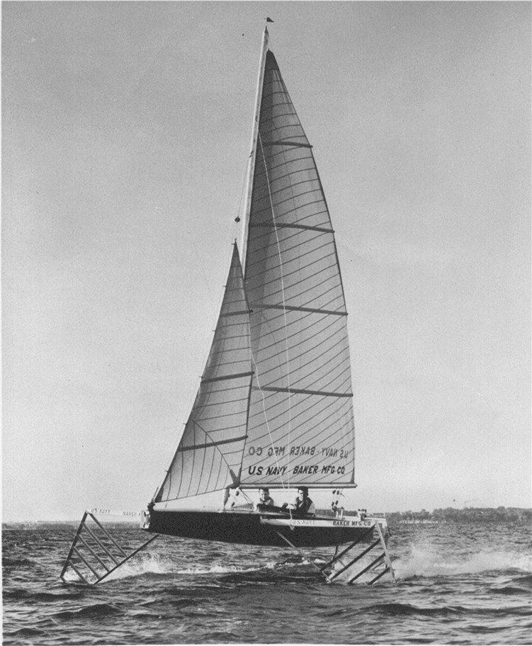
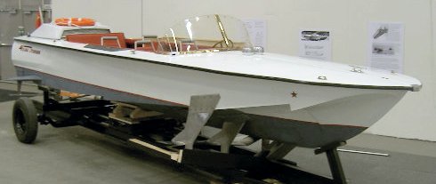
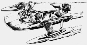
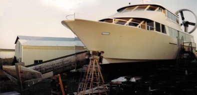
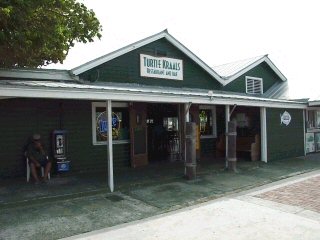
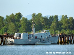
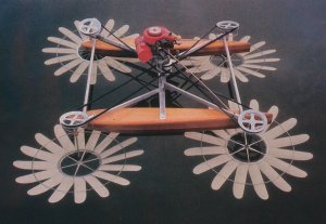
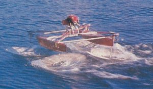
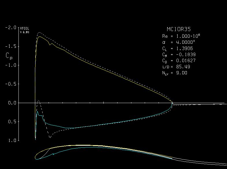
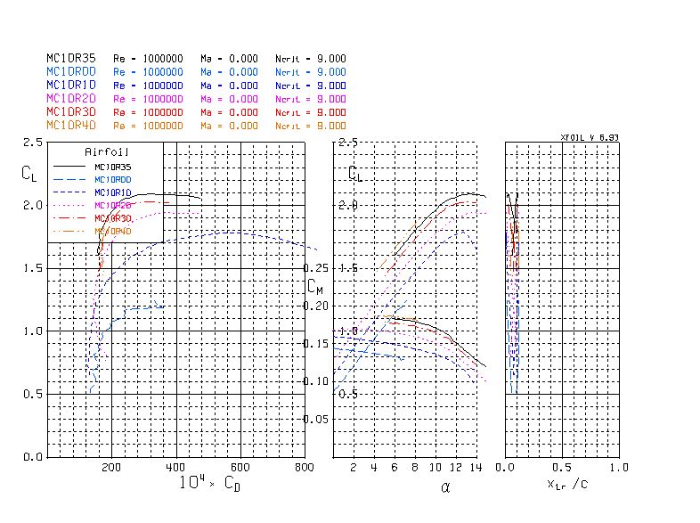