USS ARIES Museum Meeting

USS ARIES Museum Meeting

Gasconade/Hermann Missouri

18-19 October 2023


1. Registration

First, please register for the joint meeting with USS ARIES Museum by completing the form. (button below) Include the expected number of people attending the meeting. Then complete the Payment section.


2. Payment

Next, select the appropriate PayPal button(s) below for no-host dinner and no-host lunches. You may pay using an existing PayPal account, or any major credit card / debit card. 

Meeting fee plus two box lunches and group dinner: $120.00
Meeting fee plus one box lunch and group dinner: $100.00

Meeting Information and Schedule

This event will provide an outstanding opportunity for former PHM operators and Mobile Logistic Support Group (MLSG) personnel to share their experiences and participate in planning for the future of USS ARIES, PHM-5.   All those interested in hydrofoils, the PHM Program, and high-speed marine craft are encouraged to attend! 

This is also an opportunity to enjoy Oktoberfest 2023 activities in Hermann, go to:

https://visithermann.com/event/oktoberfest-in-hermann-2/

The tentative schedule is as follows:   

 Day 1 – OCTOBER 18 Wednesday

 Location: USS ARIES Museum, Gasconade, MO and Vinchester Inn, Hermann Missouri

            0900 – 1000     Sign in/coffee at USS ARIES Museum, Gasconade, MO

                                          Welcome/opening remarks by Eliot James, Ray Vellinga and Mark Bebar

            1000 – 1020      Attendee introductions/connection to PHM 

            1020 – 1030      Overview of museum tour/demos (Eliot James)

            1030 – 1130      USS ARIES walk-through (Eliot James)

            1130 – 1230      Break:  transit to Hermann for lunch – Vinchester Inn  North Star event space           

            1230 – 1330      Box lunch (sandwich/chips/soft drinks) 

            1330 – 1430      ex-PHMRON/MLSG staff experiences (informal remarks)

            1430 – 1530      USS ARIES – current restoration status and issues (Eliot James)

            1530 – 1700      USS ARIES options for the future (Eliot James – lead) 

            1700 – 1745      Break before dinner

            1745 – 1930      Group dinner Vinchester Inn – North Star event space.

   Day 2 – OCTOBER 19 Thursday 

   Location: USS ARIES Museum, Gasconade, MO                                    

            0900 – 0930 Sign in/coffee

            0930 – 1030 Discussion of USS ARIES options for the Future (Eliot James – lead) 

                                    Goal: form a small team to develop details and report back

           1030 – 1300  Craft demos

           1300 – 1400  Box lunch 

           1400 – Closing remarks/farewell at end of lunch

           1400 – 1700 Free time for Octoberfest activities / additional craft demos if needed

For information on the USS Aries Museum and PHM-5, go to:

https://www.ussaries.org/about-us and https://www.ussaries.org/uss-aries-phm-5 

The museum also includes the following high-speed craft that are in working order and will be available for demonstrations and/or rides on October 19.  

  • President Nixon’s Volga hydrofoil
  • Three Dynafoils,
  • Water Spyder
  • Hi-Foil 2

They are described on the website at the following links:

https://www.ussaries.org/president-nixons-volga

https://www.ussaries.org/dynafoil

https://www.ussaries.org/water-spyder

https://www.ussaries.org/hi-foil-2

PHOTOS

PHOTOS

Alpine Foil Blade Rider Brett Curtis, Australia Delta Kite Boards Hydrofoil Board Chairs Williwaw by David Keiper Bates Technical College DOUG HELPER FOILS Dragonfly Evolo Electric PWC Formation Flying Futuristic Foils Guillermo Sureda Burgos Hi Foil, British PWC...
Hydrofoils: Design, Build, Fly

Hydrofoils: Design, Build, Fly


Hydrofoils: Design, Build, FlyThis is a book on how to design, build, and fly hydrofoil boats. It begins with the history and theory of hydrofoils, and continues with an explanation of flight characteristics, such as; stability, control, lift, drag, cavitation, and ventilation. Foil configurations, weight and balance, flying height, and roll management are covered as well as calculations of stress, hull configuration, and wing sizing. One section demonstrates methods for comparing designs, and explores specific design ideas for motorized, human powered, and sail powered hydrofoils. Piloting and trouble shooting are followed by a bibliography and index. This very complete book includes over 270 illustrations, charts and tables on the subject of creating hydrofoil boats. Because hydrofoils fly like airplanes, except in a denser fluid, the book’s subject could be described as aerodynamics adapted to hydrofoils. It is the best book available for hydrofoil enthusiasts. There is no other book like it.

Click here For more Information at Amazon.com

Technical Journals, Papers, and Books

Technical Journals, Papers, and Books

International Hydrofoil Society Presents… 

Hydrofoil Bibliography
Hydrofoil References In Technical Journals, Papers, and Books(Mostly, But Not Entirely, Limited to Engine Powered Vessels)Last Update January 29, 2016

Sorry, no links available — Volunteers willing to create links are invited: contact IHSPresident2016@gmail.com


  • For Hydrofoil References in Popular Magazines and Books, Click Here
  • For Information on the IHS Advanced Marine Vehicle CD-ROM, Click Here
  • For More Bibliographies, Especially Sailing Related, Try the IHS Links Page)
  • For FAQs, Posted Messages, and Discussion About Hydrofoil Design Texts, Software, and Sources, Click Here
  • The Premier Sources For Descriptions and Principal Characteristics of Specific Military and Commercial Hydrofoils is Jane’s High Speed Marine Craft (formerly: Surface Skimmers, Hovercraft, and Hydrofoils) and Fast Ferry International
  • Click Here To Suggest Additional Reference(s)
  • Of course every IHS Newsletter is packed with articles about hydrofoils. To view an index of past articles in MS Excel format, Click Here

Go To IHS Main Page


  1. Abbott and Von Doenhoff, ” Theory of Wing Sections” – Old but classic book still published in paperback form by Dover Publications, Inc.
  2. Acosta, A.J., “Hydrofoils and Hydrofoil Craft,” 1973, 24 pages, California Institute of Technology, Pasadena CA USA. Sponsored in part by Office of Naval Research, Washington, DC and Naval Ship Research and Development Center, Washington, DC. Published in Annual Review of Fluid Mechanics, v5 p161-184 1973. Abstract: The successful achievements of hydrofoil craft to date and the possibility of high speeds at sea are due to the greatly increased understanding in recent years of the flow past hydrofoils and to the development of foil configurations and control systems for coping with the roughness of the sea surface. It seems appropriate, therefore, to link the discussion of hydrofoils with that of progress in the craft. The general characteristics of hydrofoil craft are reviewed together with some representative modern examples. Some physical aspects of the flow past hydrofoils are described, followed by a resume of some of the recent methods used in design and analysis of hydrofoils. Available from: National Technical Information Service; 5285 Port Royal Road; Springfield VA 22151 USA. Source Data: AD-760230 u7313. Order Number: AD-760230
  3. Alternative Hullforms for High-Performance Ferries – SNAME technical report examines the hullforms available for high-performance ferries, including planing monohulls, catamarans and other multihull vessels, small-waterplane vessels, hydrofoils, hovercraft, air-cushion vehicles, surface-effect ships, WIGs, and channel-flow-wing craft. For each type, attributes and issues are cited, and tables of principal characteristics and photographs of examples are provided. This Technical and Research Report R-51, may now be ordered from cpujols@sname.org. The 35-page report, with 22 illustrations, is being issued as a compact disk, priced at $30 ($15 for SNAME members).
  4. Altman, R., “The Design of Supercavitating Hydrofoil Wings,” Technical Report 001-14, Hydronautics Inc., April 1968
  5. Aroner, R. and R. M. Hubbard, “DEH, A High Endurance Escort Hydrofoil For the Fleet,” AIAA Paper No. 74-311, AIAA/SNAME Advanced Marine Vehicles Conference, San Diego, California, February 25-27 1974.
  6. Asseo, S.J. and F. Dell’Amico, “An analysis of three hydrofoil boat control systems,” Cornell Aeronautical Laboratories, Inc. Buffalo, 1965.
  7. “Assessment of High Speed Waterborne Vessels and Their Builders,” Advanced Marine Systems Assoc, Inc; 9421 Chatteroy PL; Gaithersburg MD; Report No. UMTA-IT-32-0001-84-5, Aug 84, 191 pages. Available from NTIS, 5285 Port Royal RD; Springfield VA 22161. Abstract: Describes eleven of the most prominent firms in the design and construction of commercial high speed watercraft (HSW) craft, both domestic and international. The objective of this report is to identify and present data on the significant HSW vehicles currently available and their builders. For a number of vehicles currently in production and in operation, data is presented on the engineering and economic characteristics, energy efficiency, maintainability, reliability, ride quality, safety, comfort, accessibility to handicapped persons, and capital and operating costs. Engineering and economic comparison of these high speed vessels are also made with other modes of transportation.
  8. Astolfi J-A, Dorange P., Billard J.-Y., Cid Tomas I., 2000, “An experimental investigation of cavitation inception and development on a two-dimensional Eppler hydrofoil,” March 2000, Journal of Fluids Engineering, Vol. 122, pp. 164-173.
  9. Bailly-Cowell, G. M. (1967). “Hamburg to las Palmas on Foils.” Hovering Craft and Hydrofoil, 6(12) pp: 10-12
  10. Baker, Jr., Robert M. L., and James S. Douglas. “Preliminary Mathematical Analysis of a Rigid-Airfoil, Hydrofoil Water Conveyance.” Journal of Hydronautics 5.4 (1971): 140-147.
  11. Ball, Edgar Scott, Jr., Lessons Learned From the Patrol Hydrofoil Missile (PHM) Program, Thesis for Master of Science in Management, Naval Postgraduate School, Monterey CA, March 1979. “The PHM Project began as a major NATO acquisition program consisting of 60 or more ships for international purchase. Today the program cosists of just six ships for the United States alone. This thesis reviews the history of the program, the design considerations and the current problems experienced by the Program Manager. An analysis of the rationale behind the decisions which led to the reduction in scope of the program suggests that factors inherent to the current systems acquisition process cause the cut back in the program and that these were independent of the Program manager’s efforts. The results of the analysis suggest that these factors have the potential to affect the outcome of any acquisition program, no matter how well the hardware performs.” Approved for Public Release. Copy located in the Defense Technical Information Center, Defense Acquisition University, Fort Belvoir VA. http://www.library.dau.mil.
  12. Bender, E., Remington, P., “Hydrofoil Design for Minimum Control Power” B.H. Beranek and Newman Report 2511, 1973.
  13. “Bibliography – High Speed Waterborne Passenger Operations and Craft,” Authors: Advanced Marine Systems Associates, Inc, Urban Mass Transportation Administration, and Peat, Marwick, Mitchell and Co.; Report No. UMTA-IT-32-0001-84-2. Aug 84, 135 pages. Available from: Office of Technical Assistance, UMTA, 400 7th ST SW; Washington DC 20590 USA. Abstract: One of seven reports written under this contract to describe high speed waterborne passenger transportation, review its applicability in the US, and document its development in the free world. This report presents a comprehensive listing of available literature (in English) on the subject of High speed waterborne passenger transportation. Each reference in the bibliography indicates the source of the document, and whether the document contains information in the following categories: vehicle characteristics (e.g., craft features, performance and human factors); design consideration’; and economic/financial analysis of such services. Over 1,200 document written prior to Sep 82 are cited.
  14. Blade and Hydrofoil Section Design – The Society of Naval Architects and Marine Engineers (SNAME) has published the technical bulletin Blade and Hydrofoil Section Design. This bulletin includes the Blade and Hydrofoil Section Design Codes with a 29 page Owner’s Guide, and a 184 page Technical Report. It updates and complements T&R Bulletin 1-17. The Design Codes and Owner’s Guide provide tools for the design and performance evaluation of blade and hydrofoil sections. The programs are provided in both DOS and Mac formats and will run on most personal computers. The Technical Report provides analytical background information and is of interest primarily to those who wish to adapt or enhance the programs. This new publication is identified as Technical and Research Bulletin 1-45. It is being issued as a CD, and may be ordered by contacting cpujols@sname.org or by calling 201-798-4800. It is priced at $50 ($25 for SNAME members).
  15. Bovee, E.C., “Design and Construction of the PC(H) Hydrofoil Patrol Craft.” Paper Presented to Northwest Section Meeting, SNAME, Seattle WA, 5-6 October 1963.
  16. Brown, DK, JP Catchpole, and AM Shand, “The Evaluation of the Hydrofoil HMS SPEEDY,” Royal Institution of Naval Architects Transactions, Volume: 126, 1984, 16p., ISSN: 0035-8967. HMS SPEEDY was procured in 1979 to provide the Royal Navy with an opportunity to gain practical experience in the operation and support of a modern hydrofoil, to establish technical and performance characteristics, and to assess the capability of a hydrofoil in the UK ‘Offshore Tapestry’ role. The present paper describes the operational and technical evaluation of HMS SPEEDY undertaken in 1980-82, and outlines the results obtained. Supplemental Information: Transactions paper; Also in Naval Architect, January 1984 issue
  17. Buermann, T.M., Leehey, LCDR P. (USN), and CDR J. J. Stillwell (USN), “An Appraisal of Hydrofoil Supported Craft.” Paper Presented at SNAME Meeting, New York, NY, 12-13 November 1953.
  18. Bullock, Otis R. and Brian Oldfield, “Production PHM Hull Structure Producibility Design,” AIAA/SNAME Advanced Marine Vehicles Conference, Arlington, Virginia, September 1976.
  19. Charlier, Jacques J., (Catholic University of Louvain), “Jetfoils on the Ostend-Dover Route: A Technical and Commercial Appraisal,” Maritime Policy and Management, Vo. 17, Issue 2, Apr 90, pp 123-132.
  20. Chatterton, H.A., T.H. Sarchin, “Challenges to Hydrofoil Ship System Technology”, Naval Engineers Journal, February 1972.
  21. Chen, Jiahn-Horng, “A Regression Relation between Cavitation Number and Cavity Length for Two-Dimensional Supercavitating Hydrofoils,” Proceedings, National Science Council ROC(A) Taipei. (Link broken “http://nr.stic.gov.tw/” on 040120wnw)
  22. Christy, John, “Punch-Packing Sea Skimmers — Boeing’s Hydrofoils Are Some of the Fastest Water-Fliers Afloat Today,” International Combat Arms, The Journal of Defense Technology, May 1985 p.39, 68-74. (Background and capability summary and photos of PHMs, plus historical reference to and photos of Soviet hydrofoils such as Mo VI, PA-4, the P-6, P-8, P-10 classes if torpedo boats (foils retrofitted), Turya class, Matka class, and Pchela class, Sparviero, Nibbio class, TUCUMCARI, FLAGSTAFF, et al.
  23. Ciancitto, Antonino, Evoluzione dei Motori e Delle Macchine Terrestri, Marittime, Aeree e Spaziali… Dell’auto Electtrica al Naviplano dal Disco Volante al Razzo Cosmico. A technical book on the evolution of the engines and of the machines for land, sea, air and space. From the electric car to the hydrofoil ship; from the flying saucer to cosmic rockets. Evolution of helicopters and jet engines. Text in Italian. Well illustrated with technical line drawings and innumerable scientific formulae. 142 pages. Softcover.
  24. Clark, D.J.,W.C. O’Neill, D.C. Wight, “Balancing Mission Requirements and Hydrofoil Design Characteristics”, AIAA/SNAME Advanced Marine Vehicles Conference, April 1978, Paper 78-725.
  25. Coates, J.T.S., R.G. Merritt, and T.C. Weaton, “Why PHM? Further Studies on Roles and Missions”, AIAA Paper 78-729, AIAA/SNAME Advanced Marine Vehicles Conference, San Diego, California (April 17-19, 1978)
  26. Colucci, Frank; “Sweeping the Sea,” Air International, Vol. 49, No. 2, August 1995, pp 73-78. Discusses airborne mine sweeping system history. It includes two photos of the Mk 105 hydrofoil sled, one of it being towed behind an MH-53E helicopter.
  27. Connor, G. G. (1967). “Power for Hydrofoils.” Hovering Craft and Hydrofoil, Vol. 6 No. (11) pp: 8-13
  28. Crew, P. R., “The Hydrofoil Boat; Its History and Future Prospects.” Quarterly Transactions, The Institution of Naval Architects, Vol. 100, No. 4, October 1958.
  29. Crimi, Peter. “Experimental Study of the Effects of Sweep pn Hydrofoil Loading and Cavitation.” Journal of Hydronautics 4.1 (1970): 3-9.
  30. Davis, Jack (Port Authority of New York and New Jersey), “Those Fabulous Flying Ferries,” Portfolio, Vol. 3, Issue 1, Mar 90, pp 33-40. Document Source: Northwestern University Transportation Library DAM2927
  31. Dogan, P., Decanico, F., Gamber, F. Mederios, R., “Hydrofoil Universal Digital Autopilot (HUD AD), Phase I Final Report” Charles Stark Draper Laboratory Report R-745, January 1973.
  32. Dogan, P., Gamber, F. S. and Decanto, F. T., “Hydrofoil Universal Digital Autopilot (HUDAP), Phase I Final Report.” Charles Stark Draper Lab, Mass. Inst. of Tech., Report 745, January 1973.
  33. Duff, Karl M., H. Schmidt, and M.R. Terry, “The NATO PHM Ship and Weapons Systems Technical Evaluation Program”, AIAA Paper 76-848, AIAA/SNAME Advanced Naval Vehicles Conference, Arlington, VA, Sept 20-22, 1976.
  34. Duff, Karl M., “The NATO Patrol Missile Hydrofoil (PHM)”, AIAA Paper No. 72-596, AIAA/SNAME/USN Advanced Marine Vehicles Meeting, Annapolis, MD, July 17-19, 1972.
  35. Duff, Cdr. Kark M. “The NATO Patrol Missle Hydrofoil (PHM).” Journal of Hydronautics 7.3 (1973): 97-103.
  36. Eames, M. C. and T. G. Drummond, “HMCS BRAS D’OR-Sea Trials and Future Prospects”, Transactions Royal Institute of Naval Architects, Vol. 115, 1973.
  37. Eames, M. C. and Jones, E. A., “HMCS BRAS D’OR-An Open Ocean Hydrofoil Ship.” Transactions Royal Institute of Naval Architects, Vol. 113, 1971.
  38. Eames, M. C., “A Review of Hydrofoil Development in Canada.” Paper Presented at 1st International Hydrofoil Society Conference, Ingonish Beach, Nova Scotia, Canada, 27-30 July 1982.
  39. Ellsworth, W. M., “The US Navy Hydrofoil Development Program-A Status Report.” AIAA Paper 67-351, Presented at AIAA/SNAME Advanced Marine Vehicles Meeting, Norfolk, VA, 22-24 May 1967.
  40. Ellsworth, W. M., “Twenty Foilborne Years – The US Navy Hydrofoil HIGH POINT, PCH-1″, David Taylor Research Center, 1987.
  41. Eppler, Richard, “Airfoil Design and Data,” Springer-Verlag, 1990.
  42. “Evaluation of the Boeing JETFOIL SPEEDY in the Fishery Protection Role”, Article in Combat Craft, p. 158, July 1983.
  43. Existing and Former High Speed Waterborne Passenger Transportation Operations in the United States, Aug 1984, Report No: UMTA-IT-32-0001-84-3; Publisher/Corporate Author(s): Peat, Marwick, Mitchell and Company; 1990 K Street, NW; Washington DC 20006, Urban Mass Transportation Administration; Office of Technical Assistance, 400 7th Street, SW; Washington DC 20590; and Advanced Marine Systems Associates, Inc.; 9421 Chatteroy Place; Gaithersburg MD 20879 USA. Abstract: This is one of seven reports written under this contract to describe high speed waterborne passenger transportation, review its applicability in the United States, and document its development in the free world. This report reviews the history of high speed waterborne passenger transportation in the United States. High speed is defined as operating at 25 knots or greater. A summary is included which outlines the principal causes of success or failure of the 19 U.S. operations in the report. Failure of high speed waterborne transportation as a public transit mode in the United States has usually been due to some combination of the following four factors: use of an unproven technology; use of only one boat; insufficient market research, resulting in the selection of routes with insufficient market potential: and insufficient capital. Available from: Urban Mass Transportation Administration; Office of Technical Assistance, 400 7th Street, SW; Washington DC 20590 USA
  44. Ford, T. (1967). Seaspeed. Hovering Craft and Hydrofoil, 6(12) pp: 30-31, 6
  45. Frauenberger, H.C., “SHIMRIT Mark II Hydrofoil For The Israeli Navy”, Paper Presented at 1st International Hydrofoil Society Conference, Ingonish Beach, Nova Scotia, Canada, 27-30 July 1982.
  46. Gallington, Roger W. “Ram Wing Surface Effect Boat.” Journal of Hydronautics 7.3 (1973): 118-123.
  47. Gamber, F. and R. Medeirus(Medetrios?), “Hydrofoil Universal Digital Autopilot (HUDAD) Phase II Final Report”, Charles Stark Draper Laboratory, Report R-817, May 1974.
  48. Gebhardt, John C., “The skin friction of a hydrofoil near a free surface,” Ann Arbor, University of Michigan, 1968.
  49. Gibson, G. R. (1967). “Expo 67 – c
  50. Giuffrida, G. (1967). “Improvement in Foilborne Navigation.” Hovering Craft and Hydrofoil, 6(11) pp: 17-19
  51. Graham, C., T.E. Fahy, J.L. Grostick, “A Comparative Analysis of Naval Hydrofoil and Displacement Ship Design”, SNAME Transactions, 1976.
  52. Graig, W. A. “Comment on “Canadian Advances in Surface-Pierciing Hydrofoils”.” Journal of Hydronautics 8.2 (1974): 74-76.
  53. Grimm, Martin, “Transverse Stability of Surface Piercing Hydrofoils,” International Hydrofoil Society Newsletter, Summer 1998, pp. 7-9. The stability criteria presented in the IMCO Code of Safety for Dynamically Supported Craft, now superseded by the International Maritime Association (IMO) High Speed Craft Code, provides an equation for assessing foilborne metacentric height (GM) of surface-piercing hydrofoils in the design stage. An alternative method which addresses several limitations of this equation has been implemented in a short computer program, and representative results for typical foil designs are presented. A more extensive assessment of the results, a source code listing, and example input files are available from the author to those willing to examine this subject in further detail and share their findings. Click Here to view the article in Adobe Acrobat format.
  54. Griswold, John W., “PHM/JETFOIL Reliability and Service Experience,” AIAA/SNAME Advanced Marine Vehicle Conference, Arlington, Virginia, September 1976.
  55. “Grumman M161 – Israel’s Combat Hydrofoil”, Defense Attaché, pp 11-21, No. 5, 1981.
  56. “Guide For Implementing High Speed Waterborne Passenger Transportation Services,” Authors: Advanced Marine Systems Associates, Inc, Urban Mass Transportation Administration, and Peat, Marwick, Mitchell and Co. Sep 84. Available from: Office of Technical Assistance, UMTA, 400 7th ST SW; Washington DC 20590 USA. Abstract: This guide is designed as a technical report for potential High Speed Waterborne (HSW) service operators, craft builders, and investors. It is intended to assist in the key tasks required to assess the feasibility of and implement HSW service. These tasks include market analysis; selecting HSW craft; fulfilling regulatory requirements; obtaining financing; and developing and implementing service. The disappointing record to date of implementing HSW service in the US demonstrated the need for this guide. This guide draws on the lessons learned from these past attempts to start HSW service in the US as well as on the experiences of many successful foreign HSW operators. It should be recognized that any compilation of data and methods for evaluation will have some limitations. Recognizing these limitations before initiating a feasibility evaluation will improve the overall accuracy of the results. Limitations can be placed in the following categories: vehicle characteristics that are continually being modified and improved; newly available and proven HSW vehicles will replace some of the HSW vehicles listed; regulatory decisions that may change from location to location and from time to time; and ridership that may be influenced by local, political, and economic considerations.
  57. Guidoni, A., Seaplanes – “15 years of Naval Aviation”, Journal R.A.S., vol. XXXII, no. 205, Jan 1928, pp. 25-64
  58. Hamilton, F. M., C.W. Pritchett, and H.H. Hudgins, “Technical and operational characteristics of high performance watercraft;” Washington, D.C. : U.S. Coast Guard, Office of Research and Development ; Springfield, Va. : Available through the National Technical Information Service, 1975.
  59. Haney, Dan G. and Stanton R. Smith, “Economic Feasibility of Passenger Hydrofoil Craft in U.S. Domestic Foreign Commerce;” prepared for Maritime Administration, U.S. Dept. of Commerce. Stanford Research Institute. Menlo Park, Calif. : [distributed by Office of Technical Services, U.S. Dept. of Commerce], 1961
  60. Hayward, L., “The History of Hydrofoils.” A Series of Articles Published in Hovering Craft & Hydrofoils, Kalerghi Publications, London, England, Vol. 5, 1966.
  61. Hefazi, Hamid; Orhan Kural; Hsun Chen; and Tuncer Cebeci, Professors; Eric Besnard, Adeline Schmitz, Kalle Kaups, and George Tzong, Research Associates, “Hydrofoil Design and Optimization for Fast Ships, Proceedings of the 1998 ASME International Congress and Exhibition Anaheim, CA, Nov, 1998. Abstract: The paper presents a multi-disciplinary design/optimization method for the conceptual design of a hydrofoil based fast ship. The method is used to determine the maximum achievable lift-to-drag ratio (L/D) of an isolated foil-strut arrangement (hopefully greater than 50) at high transit speeds (greater than 75 knots) while lifting masses of 5,000 and 10,000 tons. First, the tools necessary for the study are presented. They comprise a panel method to compute three-dimensional flows around arbitrary configurations with a model for the free surface, a foil cross-section optimization tool, a strut cross-section design tool, and a structural analysis tool. The computational tools are then integrated into a multi-disciplinary design/optimization approach, which is applied to the design of single foil and biplane configurations. Results show that the goal of L/D = 50 is achievable for 75 knots (assuming that techniques can be developed for reducing the skin friction drag to a quarter of its nominal value) and, that for 90 knots, L/D ratios around 45 can be reached. The corresponding break horsepower requirements for 10,000 tons are around 130 khp and less than 200 khp, respectively. Full text posted at: www.csulb.edu/colleges/coe/ae/ae_dept/images/pdf/asme_paper.pdf
  62. Hockberger, William A., “Defining a Ferry Business.” Paper presented at the SNAME1997 Transportation Operations, Management, and Economics Symposium at the Meadowlands Hilton Hotel, May 14-15, 1997.
  63. Hoerner, Sighard F., Dr. – Ing, Fluid-Dynamic Drag, Practical Information on Aerodynamic Drag and Hydrodynamic Resistance, published by the author, 1965 (also by the same author with Henry V. Borst: Fluid Dynamic Lift. Both books are a “must” for hydrofoil designers)
  64. Horn, Captain Frank, USN, “PHM Squadron Two Operational Experience”, AIAA/SNAME/ASNE 7th Marine Systems Conference, New Orleans, Louisiana, February 1983.
  65. Hydrofoil Handbook, Gibbs and Cox, Inc. New York, 1954. Prepared by Gibbs and Cox, Inc. acting as the design agent of the Bath Iron Works Corporation under Office of Naval Research contract NONR-507 (00)
  66. Ikonnikov, V.V. and A.I.Maskalik. Osobennosty proektirovaniya i konstruktsii sudov na podvodnykh krylyakh. L., Sudostroyenie, 1987 (“Peculiarities of designing and constructing hydrofoils”, in Russian)
  67. Imlay, Frederick H, “Theoretical Motions of Hydrofoil Systems”, NACA Report 918, 1948. Results are presented of an investigation undertaken to develop theoretical methods of treating the motions of hydrofoil systems and to determine some of the important parameters. Variations of parameters include three distributions of area between the hydrofoils, two rates of change of downwash angle with angle of attack, three depths of immersion, two dihedral angels, two rates of change of lift with immersion, three longitudinal hydrofoil spacings, two radii of gyration in pitching, and various horizontal and vertical locations of the center of gravity. Graphs are presented. This 1948 report has been posted in full on the web by NASA. “The use of hydrofoils as an alternative to planing bottoms or hulls has been of interest for some time. Guidoni advocated the use of hydrofoils as a means of improving the take-off and rough=water performance of seaplanes as early as 1911.”
  68. International Hydrofoil Society, “Proceedings of the 25th Anniversary Celebration and Conference”, Collection of Hydrofoil Papers, Washington, D.C., June 1995. (Copies still available. The cost per copy for mail delivery in the USA or Canada is US$18.50. For delivery to other countries, the cost per copy is US$25.00. Send questions about the Proceedings to IHS Treasurer. For instructions on how to order, Click Here.
  69. Irvine, James F. and Donald T. Blake, “Operational evaluation of the hydrofoil concept for U. S. Coast Guard missions, Phase I : Report of operations with the USCGC Flagstaff (WPBH-1)” Washington : U. S. Coast Guard, Office of Research and Development, 1975.
  70. Irvine, James F. and Donald T. Blake, ” Operational evaluation of the hydrofoil concept for U. S. Coast Guard missions, Phase II : Record of additional operations with USCGC Flagstaff (WMBH-1);” Washington : U. S. Coast Guard, Office of Research and Development, 1975.
  71. Irvine, James F. and Donald T. Blake, “Operational evaluation of the hydrofoil concept for U. S. Coast Guard missions, Phase III : Report of operations with USCGC High Point (WMEH-1);” Washington : U. S. Coast Guard, Office of Research and Development, 1975.
  72. Jackson, L. J., “Recent PHM Operational Experience”, ASNE Proceedings of High Performance Marine Vehicles Conference, Arlington VA, June 1992.
  73. Jaques, Bob, “Eggshells on Razor Blades Revisited: High-Speed Craft – Dismissed As Eggshells On Razorblades in Their Hydrofoil Infancy — May Have Revolutionized Ferry Operations of Late, But Old-Fashioned Safety Worries Are Resurfacing, Seatrade Review 1996
  74. Jeffrey, N. E., and W. E. Ellis. “Proteus-A Versatile Vehicle for Open-Water Hydrodynamics Research.” Journal of Hydronautics, Vol 4. No. 2, April 1970: 60-65.
  75. Jeffrey, N. E. and M. C. Eames, “Canadian Advances in Surface-Piercing Hydrofoils.” SNAME Journal of Hydronautics, Vol. 7. No. 2, April 1973.
  76. Jewell, D. A. “Hydrofoil Performance in Rough Water”, Paper presented at AIAA/SNAME Advanced Marine Vehicles Conference, San Diego, CA, February 25-27, 1974.
  77. Johnston, Robert J., and John R. Meyer, “100 Years of Overcoming Archimedes Principle”, SNAME Southeast Section Centennial 1893-1993, February 9-10, 1993.
  78. Johnston, Robert J. and O’Neill, Wm. C., “A Ship Whose Time Has Come-and Gone”, Paper presented at AIAA/SNAME Advanced Marine Vehicles Conference, Baltimore, MD, 2-4 October 1979.
  79. Johnston, R.J. and W.C. O’Neill, “The Development of Automatic Control Systems for Hydrofoil Craft”, International Hovercraft, Hydrofoil and Advanced Transit Systems Conference, Brighton, England, May 1974.
  80. Johnston, R.J., “Historical Perspective”, Hydrofoil Lecture Day, Massachusetts Institute of Technology Professional Summer, July 8, 1975.
  81. Johnston, Robert J., “History of US Involvement in Developing the Hydrofoil.” Paper Presented at 1st International Hydrofoil Society Conference, Ingonish Beach, Nova Scotia, Canada, 27-30 July 1982.
  82. Jones, E. A., “RX Craft, a Manned Model of the RCN Hydrofoil Ship BRAS D’OR.” SNAME Journal of Hydronautics, Vol. 1, No. 1, July 1967.
  83. Kaji, M., Y. Nishi, and Y. Yamagami, “Prediction Method of Motions of Hydrofoil Vessels,” Journal of the Kansai Society of Naval Architects, Issue 214, Sep 90, 6 pages. ISSN: 0389-9101. Abstract: To respond to the need for high speed transportation, the hydrofoil vessel, supported partially or totally by foil lift, has been widely investigated. Because these investigations have included few studies of hydrofoil vessel motions, however, the authors studied these motions both theoretically and experimentally. They show that the unsteady characteristics of the hydrofoil have to be included in the hydrodynamic coefficients of the motion equations used for prediction. It is also confirmed, based on experiments, that lifting link theory is useful for calculation the unsteady characteristics of the three-dimensional hydrofoil under a free surface.
  84. Kaplan, P., “Use of Jet Flapped Hydrofoils as Ships Anti-Pitching Fins”, Oceanics Report 6413.
  85. King, James H. and M. Devine, “HANDE-A Computer-Aided Design Approach for Hydrofoil Ships”, Naval Engineer’s Journal, Vol. 93, Issue: 1, April 1981. Presented at ASNE Day, 30 April-1 May 1981. Session Title: Ship Design III, Paper No. 3. Abstract: A powerful computer-aided design tool for use in hydrofoil ship engineering, the Hydrofoil Analysis and Design (HANDE) Program, is described. Its relevance, structure, features, and use are delineated. The value of HANDE for design verification and variation, research studies, and rapid response studies is related through case histories. Future application and development of HANDE and related design tools are forecast. Available from: American Society of Naval Engineers; 1012 14th Street, NW; Washington DC 20005 USA.
  86. King, James H., “The Evolution of the NIBBIO Class Hydrofoil From TUCUMCARI“, Paper Presented at 1st International Hydrofoil Society Conference, Ingonish Beach, Nova Scotia, Canada, 27-30 July 1982.
  87. King, John W., “The PHM-The NATO and US Requirements”, AIAA Paper No. 83-0614, AIAA/SNAME/ASNE 7th Marine Systems Conference, New Orleans, February 23-25,1983.
  88. Lacey, R. E., “A Progress Report on Hydrofoil Ships.” Quarterly Transactions, Royal Institution of Naval Architects, Vol. 107, No. 1, January 1965.
  89. Lang, Thomas G. “Preliminary Design of Hydrofoil Cross Sections as a Function of Cavitation Number, Lift, and Strength.” Journal of Hydronautics 4.3 (1970): 104-112.
  90. Lunde, J. K. and H. A. Walderhaug, “300 tons, 50 knots hydrofoil Craft;” second report (Johannes Krzywinski), 1916- [S.l.] : Office of Naval Research, [19??]
  91. Lynch, Thomas G., “The Flying 400”, Canada’s Hydrofoil Project, Nimbus Publishing Limited, Halifax, Nova Scotia, 1983, ISBN 0-920852-22-X.
  92. Mahig, J. “Effect of Sweep Angle and Drag on the Flutter.” Journal of Hydronautics 7.3 (1973): 104-108.
  93. Mandel, P., Seagoing Box Scores and Seakeeping Criteria for Monohull, SWATH, Planing, Hydrofoil, Surface Effect Ships, and Air Cushion Vehicles. March 1979. 98 pages, Report No: DTNSRDC/SDD-79/1 Final Rpt., ISBN: SF 43-411-291; ISSN: 62543N. Publisher/Corporate Author(s): David Taylor Naval Ship R&D Center, Bethesda MD 20084 USA. Abstract: Three seagoing box scores applicable to any vehicle operating on the surface of the ocean are defined and assessed. One of the box scores is directly useful for calculating the operational worth and the technical seagoing merit of vehicles performing ocean surveillance-like functions. The second box score is similarly useful for the ordinary transportation function of vehicles. The third box score is useful for measuring the technical seagoing merit of vehicles performing any function. This work brings together prescribed values of 18 seakeeping criteria for monohulls, small-waterplane-area twin-hull (SWATH) ships, planing craft, surface effect ships, and air cushion vehicles from sources indicated in the report. The nature of each criterion is discussed and the prescribed values of these 18 criteria for each vehicle type are compared and discussed. Although some of the prescribed values of these 18 criteria are not reconcilable, other values, obtained from independent sources, show remarkable agreement. At least one new criterion not included in Table 2 is needed for monohulls. Appendixes A, B, and C contain a useful summary of important results of Olson’s massive work in a form not presented in his work. The usefulness and limitations of the frequency and time domain ship motion data bases developed for monohulls are described in Appendix D. The existence of these two data bases makes it possible to calculate the values of several of the criteria of Table 2 by two completely independent means.
  94. Martin, M., “The Stability Derivatives of A Hydrofoil Boat – Part II”, Technical Report 001-10(II), Hydronautics Inc., January 1963
  95. Matveev Konstantin He has recently co-authored, with V. Dubrovsky and S. Sutulo, the book Small Waterplane Area Ships. In particular, he wrote a section on hydrofoils that provides simplified engineering methods for calculating lift and drag of low and high aspect ratio foils (including free surface effects), cavitation onset, vortex wash and wake behind a foil, and unsteady effects. Appendix G is on dynamic unloading and foil design, More information about this book and ordering information can be found at the Backbone Publishing web-site http://www.backbonepublishing.com/DreamHC/Page1.html. (070418 wnw)
  96. Matveev Konstantin I., and Ivan Ivanovich Matveev, “Hydrodynamic Sound Generation on a Hydrofoil,” 1996, 12th Conference On High-Speed Ship Design, Nizhiy Novgorod, Russia. Abstract: Mechanism of sound generation on a hydrofoil is considered. Mathematical model of the hydrofoil ‘singing’ effect is proposed. The frequencies of ‘singing’ are obtained. The theoretical results are compared with experiments. Contact the author to discuss: Konstantin I Matveev, email: matveev@hydrofoils.org, website: www.hydrofoils.org
  97. Matveev Konstantin I. and Ivan Ivanovich Matveev, “Estimation and Compensation of Hydrofoil Deformations During a Season of Operation,” International Hydrofoil Society Newsletter, Summer 2000; Abstract: “One of the restrictions on the use of commercial hydrofoil crafts, which have some advantages in comparison with common displacement ships, is the necessity for specialized maintenance of the foil systems. Such work usually requires complicated equipment and experienced specialists. This paper offers a new method effectively restoring a hydrofoil after foil damage. A simplified method for conservation of the lift coefficient, which greatly influences on ship’s performance, is obtained from consideration of the factors defining the lift. The technology of the process is briefly described. This method enables operators to reduce repair expenses and time drastically, which is very important during a season of operation.” Click Here to view the full text of the article. Contact the author to discuss: Konstantin I Matveev, email: matveev@hydrofoils.org, website: www.hydrofoils.org
  98. Matveev, Konstantin I. and Ivan Ivanovich Matveev, “Tandem Hydrofoil System,” Ocean Engineering 28 (2000) 253-261. Abstract: “A tandem hydrofoil system enables an improvement in the lift-drag ratio of a high -speed ship. The conditions for favorable application of this type of foil structure are determined. The data on hydrofoil boats using a tandem system are presented. The problem of the stability of the vertical plane motion for a hydrofoil with bow and stern foils is considered. The general conditions providing the stability are obtained.” Contact the author to discuss: Konstantin I Matveev, email: matveev@hydrofoils.org, website: www.hydrofoils.org. Copy can be found in libraries subscribing to Ocean Engineering, or it can be ordered directly from the publisher at http://www.elsevier.com/.
  99. Matveev Konstantin I., “Investigation of Hydrofoil ‘Singing’ in the Carman Approximation,” Phystech Journal, Vol.2, No.2, 1996. Abstract: “The effect of hydrofoil ‘singing’ has been investigated. The mechanism of sound generation is considered and a mathematical model of the process is proposed. The frequency of sound generated by a hydrofoil and the sounf intensity distribution are estimated. Experimental data are compared to calculations. Countermeasures against the hydrofoil ‘singing’ are proposed.” Contact the author to discuss: Konstantin I Matveev, email: matveev@hydrofoils.org, website: www.hydrofoils.org
  100. Merritt, R.G. and R.L. Herechkowitz, “Variations on a Single Theme: Future Configurations and Growth of the Patrol Hydrofoil Combatant (PHM)”, AIAA Paper 76-854, AIAA/SNAME Advanced Marine Vehicles Conference, Arlington, Virginia (September 20-22, 1976)
  101. Meyer, John R., and James R. Wilkins, “Hydrofoil Development and Applications” ASNE Proceedings of High Performance Marine Vehicles Conference, Arlington VA, June 1992.
  102. Meyer, John, Ships That Fly. About 10 years ago John collected a lot of material about hydrofoils and put it all together in a book called Ships That Fly. It became a story of the modern hydrofoil covering the early days of hydrofoil inventors and experimenters and taking the reader through over 150 pictures and illustrations of hydrofoils leading to those of recent years. He recently had the pages of the book scanned and put in a pdf file and placed on a CD that is being offered for sale.You will note that Chapter 6, The US Navy Fleet Hydrofoil-PHM, ends with a very optimistic view of PHMs in the current US Navy, and larger hydrofoils in its future. However, this was not to be. Several years following the completion of my book, Ships That Fly, there were events surrounding the US Navy PHM program that are described in an Addendum to Chapter 6. All six PHM ships were decommissioned on July 30, 1993. This was the only time the US Navy has decommissioned an entire class of ships on the same day. This addendum describes some of the events leading to this sad day for the US Navy and the hydrofoil community. Also, documented are the many attempts to save the Ship, the day of the ceremony, attempts to save the ships even after the decommissioning, and finally the subsequent disposal of the ships and their status today.John also collected a series of over 140 hydrofoil pictures and illustrations, and created a Hydrofoil Slide Show, entitled: A Century of Hydrofoil Development. All three of these files are on the CD. To find out more, log onto: http://themeyers.org/ShipsThatFly/index.html
  103. Miller, Boyce E., and Harvey P. Hack. “Impressed-Current Cathodic Protection.” Journal of Hydronautics July 1973: 108-111.
  104. Mitchell, T. R. … [et al.] “Hydrofoils for the fisheries law enforcement mission of the U. S. Coast Guard;” Washington : U. S. Coast Guard ; Springfield, Va. : Available through the National Technical Information Service, 1975.
  105. Mitchell, T.R., J.P. Donnelly, and J.A. Nevendorffer, “Observations of the performance of TUCUMCARI (PGH-2) in the U.S. Coast Guard mission oriented trials;” Arlington, Va., Center for Naval Analyses, 1973.
  106. Mitchell, T. R., L. S. Cohan, and C. H. Heider, “The utility of high-performance watercraft for selected missions of the United States Coast Guard;” Center for Naval Analyses, Arlington, Va. Arlington, Va. 1972.
  107. Modern Ships and Craft, Chapter V – Hydrofoils, Special Edition of the Naval Engineers Journal, February 1985. (Contact IHS for a copy).
  108. Moorwood, John, “Hydrofoil Options.” Amateur Yacht Research Society (AYRS), #90 July 1998 – Covers different design ideas and approaches for sailing hydrofoils.
  109. Myers, G.R., “Observations and Comments on Hydrofoils”, Paper Presented at the Society of Naval Architects and Marine Engineers Spring Meeting, Seattle, WA., May 13-14, 1965.
  110. Noreen, A.E., P.R. Gill, and W.M. Feifel, Boeing Marine Systems, Inc., “Foilborne Hydrodynamic Performance of Jetfoil,” Journal of Hydronautics, Vol. 14, No. 2, Apr 1980, pp. 56-62. The Boeing Jetfoil Model 929-115 hydrofoil ship was derived from Model 929-100, with increased forward foil area for larger load-carrying capacity. Forward and aft foil contours were revised to increase cavitation margin. New hydrodynamic design methods were employed to maximize foil thickness for minimum structural weight. Prediction of foilborne cruise performance was based upon theoretical analysis, model test data, and full-scale trial data from Model 929-100. Extensive flowfield observations were made of the foil systems during sea trials of the first Model 929-115 produced. Good agreement was found between predicted and observed cavitation and ship performance characteristics. Sensitivity of ship performance to operating variables was determined from sea trial data.
  111. Norwegian Institute of Transport Economics (1967). “Hydrofoil Boats or Hovercraft?.” Hovering Craft and Hydrofoil, 6(11) pp: 24-27
  112. Oakley, O. H., “Hydrofoils-A State of the Art Summary.” Proceedings of the Institute of Aeronautical Sciences, National Meeting on Hydrofoils and Air Cushion Vehicles, 17-18 September 1962.
  113. Olling, D.S., and R.G. Merritt, “Patrol Combatant Missile Hydrofoil-Design Development and Production – A Brief History”, High Speed Surface Craft, January-February 1981.
  114. “Operational testing and evaluation of the hydrofoil seacraft DENISON from June 1962 through 1963.” Grumman Aircraft Engineering Corporation. [Bethpage, N.Y., 1963?]
  115. Ostersehlte, Christian, “Tragflächenboote von der Unterweser — Die BREMER PIONIER und ihre beiden Vorgänger,” Bremisches Jahrbuch, Band 79, 2000, pp. 145 – 196. The predecessor boats of the title are the Focke-Schaper-Tragflächenboot (Aug 1951) and TOM-TOM II (Oct 1951).
  116. Patch, David A., “Operational Utilization of the Patrol Hydrofoil Missile (PHM)”, First International Hydrofoil Society Conference, Ingonish Beach, Nova Scotia, Canada, July 27-30, 1982.
  117. Peek, R. and L. Bauer, “M-151 Transmission for Mark II Hydrofoils,” AIAA-2084, September 1981.
  118. Petrie, D. M., “Operational and Developmental Experience on the US Navy Hydrofoil HIGH POINT.” AIAA Journal of Aircraft, Vol. 3, No. 1, January-February 1966.
  119. Pieroth, C., “Grumman Design M163, a 2400 Metric Ton Air Capable Hydrofoil Ship”, AIAA Paper 78-749, AIAA /SNAME Advanced Marine Vehicles Conference, San Diego, CA, April 17-19, 1978.
  120. Plotkin, A. “Laminar Boundary-Layer Induced Wave Forces on a Submerged Flat-Plate Hydrofoil.” Journal of Hydronautics 8.2 (1974): 47-52.
  121. Prandtl, Ludwig and Oscar G Tietjens; Applied Hydro- and Aeromechanics, ISBN: 048660375X. A text book of over 300 pages (5-3/8” x 8-1/2”). Prandtl was a leading aerodynamics theorist. This work has is reported as “one of the finest introductory works in the field”. Topics include flow through pipes, Prandtl’s own pioneering work on boundary layers, drag, airfoil theory, and entry conditions for flow in a pipe. Professor Tietjens is known for his research and development of experimental hydrofoil boats prior to and during the second world war. While it is uncertain whether the book deals specifically with hydrofoil hydrodynamics, it is listed by IHS due to the association of at least one of its authors with hydrofoil craft development. The book could be ordered through DoverPublications.com for $10.95 when this reference was spotted.
  122. Report to Congress: Study of High Speed Waterborne Transportation Services Worldwide, August 1984, Publisher/Corporate Author(s): Peat, Marwick, Mitchell and Company ; 1990 K Street, NW; Washington DC 20006, Office of the Secretary of Transportation ; 400 7th Street, SW; Washington DC 20590, Advanced Marine Systems Associates, Inc.; 9421 Chatteroy Place; Gaithersburg MD 20879 USA . Abstract: In response to Congressional mandate, UMTA engaged in an extensive evaluation of high speed waterborne (HSW) passenger transportation in the U.S. and throughout the free world. The study reviewed the history of HSW, determined its current status and examined factors that might impact its future development. Unsubsidized HSW operated by the private sector was emphasized in analyzing potential U.S. sites. The U.S. site analyses included domestic, as well as foreign craft. High interest rates and the investment required to establish HSW service make the financial feasibility of operations sensitive to the cost of capital. A vessel capable of satisfactory service must also have low initial costs and be economical to operate and maintain. As a group, craft of foreign origin meet these criteria best. Were foreign technology employed, the study indicated that HSW service could be operated profitably by the private sector in some markets. A study of 10 such sites, indicated that nine might, under certain conditions, be feasible. Conditions are: (1) Competitive in time with other transport services, (2) Competitive in cost; (3) Need to capture only a small share of an existing travel market for economic viability. Primary market for HSW abroad is travel times under 45 minutes. Despite relatively high seat-mile costs, travelers abroad often pay a premium fare for travel time savings, convenience and/or novelty of HSW. HSW craft operate safely in great variety of adverse locations. Foreign HSW development has been orderly with private sector and unsubsidized service often viable. In contrast, in the U.S. HSW has been beset by inadequate capitalization and has operated with unproven vessels. Available from: Office of the Secretary of Transportation ; 400 7th Street, SW; Washington DC 20590 USA; ID: 00390706
  123. “Review of Selected High Speed Waterborne Operations Worldwide,” Authors: Advanced Marine Systems Associates, Inc, Urban Mass Transportation Administration, and Peat, Marwick, Mitchell and Co.; Report No. UMTA-IT-32-0001-4, Aug 84. Available from: Office of Technical Assistance, UMTA, 400 7th ST SW; Washington DC 20590 USA. Abstract: One of seven reports written under this contract to describe high speed waterborne passenger transportation, review its applicability in the US, and document its development in the free world. This report describes high speed waterborne passenger transportation operations throughout the world. Information is presented on: ridership, the type, characteristics and number of craft used, operating conditions and characteristics, crew sites and wages, terminal facilities and maintenance procedures. The operators described were chosen because they exemplify the most frequently used types of craft and operating scenarios. Services are included that operate in Europe, South America, and the Far East. Not all existing operations are covered in this report due to time and budget limitations.
  124. Rieg, Donald F. and James H. King] “Technical evaluation of the RHS 200 for high speed ferry applications and Coast Guard missions ;” prepared for U.S. Department of Transportation, United States Coast Guard, Office of Research and Development. Rieg, Donald F. Washington, D.C. : The Office ; Springfield, Va. : Available through NTIS, 1984.
  125. Rodriquez, Leopoldo, Dino Di Blasi, “Current Status and Future Prospects for European Commercial Hydrofoils”, Paper Presented at 1st International Hydrofoil Society Conference, Ingonish Beach, Nova Scotia, Canada, 27-30 July 1982.
  126. Roess, R.P. and P.J. Grealy, “The Use of High-Speed Vessels in Urban Ferry Service: Issues and Economic Evaluation,” Transportation Research Record, Issue: 925, Inland Water Transportation. 1983. pp 9-12, Publisher/Corporate Author(s): Transportation Research Board; 2101 Constitution Avenue, NW; Washington DC 20418 USA; Abstract: The economic aspects of high-speed ferry operations are discussed and compared to conventional ferry services. The economic viability of high-speed service is demonstrated using conventional economic analysis techniques. Issues related to high-speed ferry operations such as safety, efficiency, and ridership attraction are discussed in more general terms. The paper concludes that high-speed ferry operations can compare favorably with conventional services and hold potential for attracting larger numbers of passengers and charging premimum fares. :Available from: Transportation Research Board Business Office; 2101 Constitution Avenue, NW; Washington DC 20418 USA. Order Number: DOTL JC
  127. Salvesen, Nils. “Seakeeping Characteristics of Small-Waterplane-Area-Twin-Hull Ships.” Journal of Hydronautics 7.1 (1973): 3-9.
  128. Schrider, M., “Study of Foil Influence on Foil-Borne Hydrofoil Performance”, Intersociety Advanced Marine Vehicles Conference, Arlington, VA, 5-7 June 1989.
  129. Shen, Y., Wermites, R., “Recent Studies of Struts and Foils for High Speed Hydrofoils” Marine Technology, Vol 16, January 1979.
  130. Shultz, W.M., “Boeing JETFOIL Model 929-100”, AIAA Paper No. 74-308, AIAA/SNAME Advanced Marine Vehicles Conference, San Diego, CA, February 25-27, 1974.
  131. Shultz, W.M., “Current Status And Future Prospects United States Commercial Hydrofoils”, Paper Presented at 1st International Hydrofoil Society Conference, Ingonish Beach, Nova Scotia, Canada, 27-30 July 1982.
  132. Sinnarwalla, Abbas M. and T. R. Sundaram, “On the changes in lift of hydrofoils due to surface injections of polymer additives;” Laurel, Md. : Hydronautics, Inc., 1978.
  133. Stark, D.R., “Ride Quality Characterization and Evaluation in the Low Frequency Regime, with Applications to Marine Vehicles,” Human Factors in Transport Research Volumes 1 and 2, Academy Press Inc. (London) LTD, and Conference on Ergonomics and Transport, Swansea, United Kingdom, 1980.
  134. Stark, D.R., “The PHM Automatic Control System”, SAE National Aerospace Engineering and Manufacturing Meeting, San Diego, CA, Oct. 1974.
  135. Stevens, D. L., Jr., “The Bureau of Ships Hydrofoil Craft FRESH-1.” Paper Presented to Chesapeake Section, SNAME, 26 February 1964.
  136. “Study of High Speed Waterborne Transportation Services Worldwide”, Urban Mass Transportation Agency, UMTA-IT-32-0001-84-3, August 1984, Seven Vols., National Technical Information Service (NTIS) #PB 85129906/U.
  137. “Study of Hydrofoil Seacraft” Vols. I and II, PB161759, 3 Oct 58, Phase I Technical Report by Grumman Aircraft Engineering Corporation to Maritime Administration, US Department of Commerce. “This report contains the results of a parametric study made to determine the feasibility of hydrofoil seacraft with speeds from 50 to 200 knots, gross weights from 100 to 3,000 tons, and ranges from 400 to 3,600 nautical miles. The relative merits of various combinations of hydrofoil craft parameters and the possible advantages of such craft over displacement vessels were thoroughly investigated. A detailed analysis of the various design features and operational characteristics of hydrofoil craft… is also included.”
  138. Sueoka, H, Tozawa, S., Sakai, F., Kabata, T.,”Structural Responses of Mitsubishi Super Shuttle 400, Rainbow, in Seaways”, Mitsubishi Heavy Industries, Ltd. (Japan), FAST ’95 Conference.
  139. Sugranyes Baena, Alcides, “‘KOMETA-M’ – Description and Handling of USSR Coastal Passenger Hydrofoil,” Hovering Craft and Hydrofoil, Kalerghi Publications, Vol. 1 No. 11, Aug 72
  140. Sullivan, E. K. and Higgins, J. A., “Test and Trials of the HS DENISON.” Published by the Maritime Administration, circa 1962.
  141. Swales, P. D., R. C. McGregor, and A.J. Wright. “Correlation of Force Measurements and Separated Flow Regions on Surface Piercing Struts.” Journal of Hydronautics April 1974: 72-73.
  142. Swales, P. D. R. C. McGregor,and A. J. Wright. “Explanation of Forces on a Surface.” Journal of Hydronautics July 1973: 132-133.
  143. Taiwan 106-36 Republic of China, Vol. 24, No. 2, 2000, pp. 120-129. Abstract: For convenience in engineering applications, we attempt to find a general regression relation between the nondimensional cavity length and the cavitation number for two-dimensional supercavitating hydrofoils. Based on observations of the general trend of the relation, a nonlinear function for these two physical quantities is proposed, and the coefficients in the function are optimally determined via a least-squares procedure and an iterative Gauss-Newton method. Several supercavitating hydrofoils, including flat-plate hydrofoils and hydrofoils with and without cambers, are investigated. The results seem to indicate that there exists a global approximate relation, the optimum coefficients of which depend on the flow conditions and hydrofoil shape. Key Words: 2-D supercavitating hydrofoil, potential flow, regression relation. Full text posted at: http://nr.stic.gov.tw/ejournal/ProceedingA/v24n2/120-129.pdf
  144. Terao, Yutaka; “Lateral and Roll-Yaw Coupled Motion Control of Hydrofoil Craft”, Proceedings of the 7th International Conference on Stability of Ships and Ocean Vehicles (STAB 2000), 7-11 February 2000, Launceston, Tasmania, Australia. AMECRC Ltd, Editor: Martin Renilson. pp 542 – 550. For those with a really technical bent, the mathematical modeling of the human operator using skilful body weight shift to maintain stability of a solar powered hydrofoil has been examined in this reference.
  145. Terao, Yukata; (Tokai University, Dept. of Naval Architecture, Japan) and H. Isshiki (Hitachi Zosen Corp, Japan), “Wave Devouring Propulsion (WDP) Sea Trial,” Undated. Abstract: The development of Wave Devouring Propulsion system and results of its sea trial on the HOKUTO are presented. WDP system is an idea not only for the ship propulsion system which converts wave energy directly into thrust but also the ship motion reduction system. This system consists of a ship hull and a hydrofoil installed at the bow. Improvement of the propulsive efficiency in waves and high seaworthiness is measured during the sea trial. Click Here for full text on line.
  146. Tietjens, O., “Das Tragflaechenboot.” Werft Reederei Hafen, Jahrg. 18, Heft 7, April 1, 1937, pp 87-90 and Heft 8 April 10, 1937 pp. 106-109.
  147. Unruh, J. F., and R. L. Bass III. “Doublet Lattice-Source Method for Calculating Unsteady Loads on Cavitating Hydrofoils.” Journal of Hydronautics 8.4 (1974): 140-147.
  148. Van Bibber, V. H., “The Major Problems of Hydrofoil Craft,” Lockheed Shipbuilding and Construction Company paper presented at the SNAME Hydrofoil Symposium 13-14 May 1965 Spring Meeting in Seattle Washington. Major problem areas discussed in this paper are, Propeller Designs, Manufacture of Hydrofoils and Mating of Subassemblies, Galvanic Protection, and Crew Habitability.
  149. van Walree, Frans, “Computational Methods for Hydrofoil Craft in Steady and Unsteady Flow,” doctoral thesis, available to the public at a cost of NLG 100 (approx. US$50), by sending a request to Maritime Research Institute Netherlands, Attn: Ms. R. Jurriens, Librarian; PO Box 28; 6700 AA Wageningen, Netherlands. Tel: +31-317-493417, Fax: +31-317-493245, email: Rjurriens@marin.nl.
  150. Vermeulen, Johan C., Roderick A. Barr, Milton Martin, “Hydrodynamics of Hydrofoil Craft Subcavitating Hydrofoil Systems,” Hydronautics, Inc. Technical Report 463-1, April 1964
  151. Vogt, James E., “Automatic Control of the Hydrofoil Gunboat, TUCUMCARI,” AIAA 2nd Advanced Marine Vehicle and Propulsion Meeting, AIAA Paper No. 69-729, 1969.
  152. von Schertel, Baron Hanns, “European Development of Hydrofoil Craft Technology”, Paper Presented at 1st International Hydrofoil Society Conference, Ingonish Beach, Nova Scotia, Canada, 27-30 July 1982.
  153. von Schertel, Baron Hanns, “Design and Application of Hydrofoils and Their Future Prospects,” Institute of Marine Engineers-Transactions, Series A, Part 3, Vol 86, 1973, pp 53-64. Institute of Marine Engineers; Memorial Building, 76 Mark Lane; London EC3 7JN England; Abstract: The performance characteristics of hydrofoil craft are compared with those of other water craft with regard to lift/drag ratio, power requirement, speed loss in waves and sustained accelerations, special attention being paid to the hovercraft. The advantages and state of development of the foil systems currently in use are examined, and their commercial and military applications described. The different propulsion systems and their efficiencies are discussed. Finally the future of the hydrofoil is visualized, the prospects of the known foil sections for surmounting the speed barrier being appraised. The presumable size limit of future craft is considered.
  154. Wang, J. & Mcowan, S., “Fast Passenger Ferries and Their Future,” Maritime Policy and Management, Vol. 27, Issue 3, Jul 00, pp 231-251. Published by Taylor and Francis, Ltd.; 1 Gunpowder Square; London EC4A 3DE, England. (USA address: 1900 Frost RD Suite 101; Briston PA 19007). Abstract: Examines the different choices of high speed craft (HSC) hull design available and briefly looks at the advantages and disadvantages of each hull form. The trends in various design aspects of HSC such as speed, capacity, and size are studied. An investigation on HSC development is conducted, and the future of HSC in the United Kingdom is studied. A study onboard an HSC with the aim of trying to determine what passengers think of HSCs and why the travel by them is also conducted. Finally, an analysis of the possible market for HSCs is carried out.
  155. Weber, D. (1967). “New Worlds to Conquer.” Hovering Craft and Hydrofoil, 6(12) pp: 3, 6
  156. Wennagel, G. J., “Characteristics of the US Maritime Administration Hydrofoil Test Vehicle.” Paper Presented at SAE National Aeronautics Meeting, 1961.
  157. Williams, R.E and P.L. Ehrman, “Operational evaluation of the hydrofoil concept for U. S. Coast Guard missions: executive summary;” Washington : U. S. Coast Guard, Office of Research and Development ; Springfield, Va. : Available through the National Technical Information Service, 1975.
  158. Wright, H.R. and F.W. Otto, “The Hydrofoil Craft Drag Polar,” Journal of Hydronautics, October 1980.
  159. Wright, H. Raymond, Jr. (Grumman Aerospace Corp) and Frank W. Otto (Edo Corp), “Hydrofoil Craft Drag Polar,” Journal of Hydronautics, Vol 14. No. 4., Oct 1980, pp. 111-116. Adaptation of the friction and wave drag components to the classic aerodynamic drag polar are shown with accommodation for the weight/center-of-gravity envelope. The parametric forms of the drag, power, and specific range and endurance curves are shown and related to the traditional dimensional forms. The relationship between the drag polar and the propulsion is indicated.
  160. Yagi, T., et al, “Jetfoil Operational Experience in Japan”, ASNE Proceedings of High Performance Marine Vehicles Conference, Arlington VA, June 1992.

    This Page Organized by R. Terry Black; Maintained By…

International Hydrofoil SocietyP.O. Box 157 – Hume, VA 22639 – USAwebmaster@foils.org

IHS is not a source for copies of the articles cited above except where otherwise noted. If any library would like to start a special collection of hydrofoil reference material, IHS would like to hear from you… it is possible that we could assist in starting and building your collection.


Click Here To Suggest Additional Reference(s)Go To Main Page


Disclaimer: IHS does not endorse or recommend specific products or services, nor does IHS accept paid advertising. However, the Links Out and BBS pages features sellers of many hydrofoils and related products as a service to the hydrofoil community.

Please report any technical problems with this website by email to: webmaster@foils.org

Hydrofoil, Rudder, and Strut Design Issues

Hydrofoil, Rudder, and Strut Design Issues

International Hydrofoil Society Correspondence Archives…

Hydrofoil, Rudder, and Strut Design Issues
(See also links to design texts and other technical information sources on the IHS Links Page)
(Last Update: 11 Nov 03)Return to the Archived Messages Contents Page
To search current messages, go to the Automated BBS


Correspondence

Where is Foil Design Data?

[11 May 03] Where do I go for specifics about foil design? As in how do I determine the size, aspect ratio, need for winglets, shape, (inverted T vs. inverted Y vs. horizontal V), NASA foil specification . My plan calls for a single foil fully submerged with all control being accomplished with above water airfoils (pitch, roll, direction). Everything above water is conceptually set, but I have limited understanding / knowledge about foils. I understand that there are arrangements combining a lower speed and higher speed foil on the same vertical column, with some type of grooving on the higher speed foil to prevent cavitation at limited angles of attack. With respect to the website http://www.supramar.ch/ there is an article on grooving to avoid cavitation. I anticipate a limited wave surface (off shore wind) so elevation could be limited, and the initial lifting foil would be unlikely to be exposed to resubmersion at speed. Supramar is willing to guide/specify the grooving at no charge, but I need a foil design for their review or at least that seems to be the situation. I have not actually asked for a design proposal. Maybe I should. Actually it is hard to know if my request would even be taken seriously. They did communicate initially but subsequent emails have been unanswered. Any instruction, constructive criticism, or guidance would be appreciated. Of note the current land speed record for a kite/sail powered tricycle vehicle is just a touch over 72 mph in 40-50 mph winds. — Duncan Coolidge (jcoolidg@tds.net)

Response…[11 May 03] We frequently get requests like this. The answer is not simple, but there is a lot of help within the organization and on the website. I advise first checking out the site, and at the same time order a copy of the Advanced Marine Vehicle (AMV) CD-ROM #1 announced on the site. This CD has a lot of foil design info. — John Meyer (jmeyer@erols.com)

What NACA Series is Best?

[15 Mar 02] I am studying in Naval Architecture Department, Ocean Engineering Faculty, Sepuluh Nopember Institut Of Technology, Surabaya Indonesia. Before I complete my studies, I must do experiments as requirement from my college. I want to experiment with about lift and drag for a foil of a Hydrofoil Craft. This experiment is using Computational Fluid Dynamic (CFD) with ANSYS 5.6. But I am confusing about what NACA Foil Series is suitable for Hydrofoil Craft, and what the principal reason for choice this NACA Series. — Hot Pungka Purba (pungka@yahoo.com)

Response…[15 Mar 02]You haven’t said what the requirements are for your section. Since you mention NACA foils, I assume that you are interested in the subcavitating speed range. You need to have some idea of the range of lift coefficients are required of your foil – this is driven by the load the foil has to carry and the variation in angle of attack the foil will experience as it goes through waves. Something like Cl = 0 to 0.6 with a design Cl = 0.3 would be typical. The intended speed range for the vessel is critical – what are the takeoff, cruise, and dash speeds? And you need to know how the craft will be controlled – will the foils be surface piercing or fully submerged, and will they change incidence or have flaps?

I believe there are four key problems in subcavitating hydrofoil section design. First, you want to avoid separation because this invites ventilation as well as causing drag. Second you want to avoid cavitation. Of course, you also want low drag, and fortunately the things you do to get a high cavitation speed and avoid separation are also good ways to minimize the drag. Finally, the section may be operating close to a free surface, and this modifies the velocity distribution about the foil.

Since cavitation begins when the lowest pressure anywhere on the foil drops below the local vapor pressure of water, you want to minimize the maximum velocity. That means no sharp pressure peaks allowed! At the same time, you want the average velocity over the top surface to be as high as possible so as to produce the most lift. This drives the design to shapes which have long, flat pressure distributions – shaped like building with a flat roof.

The NACA sections which have this type of rooftop velocity distribution are the 6-series laminar flow sections and the earlier 1-series (i.e., 16-012, etc). The 1-series sections have a shallow favorable pressure gradient back to 60% chord, but they have a highly convex pressure recovery that is not necessarily a good characteristic if one wants to avoid separation at the trailing edge. So a comparable 6-series section (say, 66-XXX) would probably be a better bet than the corresponding 16-XXX section.

There are other more modern hydrofoil sections, such as the Eppler designs. Try to get his book, “Airfoil Design and Data”. It is out of print, but your engineering library should be able to find it. He talks about the philosophy of hydrofoil design and has several sections specifically designed to be hydrofoils.

You can also design your own hydrofoils using XFOIL, which you can download for free. XFOIL is more modern code than the Eppler code, but you can still design sections like Eppler’s using XFOIL. This would be a good start to analyzing with ANSYS because ANSYS doesn’t have the inverse design capability of XFOIL but it does have a more powerful analysis capability. So you would be able to compare the experimental results, the inviscid + integral boundary layer results, and the Navier-Stokes CFD results, at least for subcavitating flows.

Simulating the two-phase flow that results from cavitation would be a difficult challenge! But it has been done, and this makes a Navier-Stokes method worthwhile. Unfortunately, much of the research has been done using NACA 4-digit sections (like 0012, 0015), and I suspect this is either out of ignorance as to what makes a good hydrofoil, or perhaps because these are bad hydrofoils and cavitate more easily!

Say you are concerned with a fully submerged hydrofoil with flaps to control the height of the vessel. As the boat flies through waves, the orbital velocity of the waves will change the angle of attack on the foil and thus the lift. The control system will try to compensate for this by moving the flap. If the boat is flying along perfectly level, a good approximation of a perfect control system would be one that maintained a constant lift coefficient on the foil as the angle of attack changed. Thus you need to consider three cases: zero angle of attack with the flap at neutral, positive angle of attack with the flap deflected up, and negative angle of attack with the flap deflected down. The larger the flap deflection, the greater the angle of attack change that can be tolerated while still maintaining the same lift coefficient, and the higher the sea-state in which the ship can operate. For each of these three cases, the peak velocity will occur on a different part of the foil. You would want to design the foil so that the value of the peak velocity is the same in each case. This will give you the highest speed without cavitating. But larger flap deflections and a greater angle of attack range means higher maximum velocities and thus a lower operating speed without cavitating, so there’s a tradeoff between the ability to operate in rough seas and the vessel’s maximum speed. It’s an interesting design problem! But one that comes back to knowing the original requirements in order to design (or select) the appropriate section.

Take a look at …

— Tom Speer (me@tspeer.com) website: www.tspeer.com

Just after I pushed the “Send” button for the preceding email, I found a good link about using Fluent to calculate cavitating flows, but I didn’t save the link. I can probably find it again if anyone is interested. I’ve also thought some about why the 16-XXX sections are so popular for hydrofoils over the 6-series, and I think it must be because they have a much thicker and stronger trailing edge. So perhaps I was too hasty in recommending the 6-series because they may not be practical for the very high loadings of hydrofoils. Flexing of the trailing edge can lead to singing, too. By the way, there are some interesting papers at U. Mich. on their large-scale hydrofoil (8′ chord!) test. — Tom Speer (me@tspeer.com) website: www.tspeer.com

Foil Design Guidance Needed

[4 Feb 02] I am restoring and optimizing a 1969 Irwin 24. Its keel has an “L” design fin and ballast torpedo. The foil consists of a one inch thick steel plate encased in fiberglass and faired to a section that is similar to NACA 00-series sections through station 6; then tapers to a blunt trailing edge. I have some experience with symmetrical foil optimization; however always with sections in the 8% to 12% thickness range (and no data on less than 6% thickness). I have never implemented a foil less than 7% (even when strength and ballast were not considerations) and I am contemplating taking one of two options:

  1. Maintaining the thin section, leaving the foil in tact (excepting minimal fairing) through section 6, tapering the trailing edge to 1/16th inch and squaring off (this may require increasing the span ~3 inches); making the foil a very close approximation of a NACA 00-series section with 4% thickness.
  2. Building up the existing foil section to a NACA 0006 or NACA 0008 section (this may require increasing the span ~1 inch and add approximately 100 pounds to the displacement).

Option 1 is far less work, but would change the plan form design slightly. I am not particularly worried about moving the center of lift slightly back because I have removed a 6 inch deep skeg that was a retrofit between the keel and rudder. In any event I am keen on cleaning up the trailing edge. Option 2 would be a good deal of work that would require some benefit to justify undertaking. The plan form data on the keel is as follows: Span = 24 inches, Chord = 45 inches, Max thickness = 2 inches, Sweep Angle = 45 degrees. The torpedo height is 12 inches, the torpedo is V shaped where it meets the foil (120 degrees at the foil interface and the at the bottom) and has a total length of 58 inches. Total displacement is 3000 pounds. Thanks for any guidance you can afford me. — Tom Graham (TGraham@entergy.com)

Response…[6 Feb 02] Paul Bogataj had an article in Sailing World a while back concerning keel sections and leading edge shapes. I’d download XFOIL and use it to look at different sections. You can put in your section as it is, NACA sections for comparison, and use it to make modifications to either. — Tom Speer, F-24 AMA DEUS (me@tspeer.com) website: www.tspeer.com

Rudder Cavitation Design

[3 Feb 02] The rudder cavitation article in the Winter 01-02 Newsletter got my interest. The hydrofoil strut has a similar sea state problem. We tailored the strut section pressure distribution along the strut to reduce its cavitation sensitivity. If you are interested I would be glad to talk with you about the work we did. My comment is based on the ongoing research effort we had at Boeing Marine Services (BMS) relating to hydrofoils. The research combined our hydrofoil experience with the aero capability imported from our airplane organization. The work was reported in Boeing documents and IRAD reports-David Taylor was always on the distribution list. We presented a paper at the 19th Tow Tank Conference giving a brief report on the Jetfoil forward foil. — Bob Dixon (dixon.bob@comcast.net)

Responses…[3 Feb 02] I’d like to hear more about it. I wonder if many strut “cavitation” problems are really ventilation problems, and if what one would do with the pressure distribution would be somewhat different in the two cases. To prevent cavitation, did you try to cap the peak velocity by using a roof-top pressure distribution, carried as far aft as possible? This would also be consistent with natural laminar flow control. — Tom Speer (me@tspeer.com)

[3 Feb 02] Thanks for the info. All of the Boeing reports are in the Advanced Ship Data Bank at NSWCCD (David Taylor). Do you have a copy of the paper from the 19th Towing Tank Conference? That may not be in the Data Bank. If you could send it, I would copy it and send it right back. It may be good to include in the next AMV CD we may be putting out at IHS. — John Meyer (jmeyer@erols.com)

Turning Circle Explanation

[25 Nov 01] I need a brief explanation about measuring the turning cycle of a ship (HSLC). — Yuksel UNAL (yunal@ssm.gov.tr)

Responses…[25 Nov 01] The answer to the question can be found in Vol. III of SNAME’s Principles of Naval Architecture, pp.316 and Fig.157. — Bill Buckley (wbuckley@erols.com)

[25 Nov 01] You have asked about the measurement of the ‘turning cycle of a ship’ and I presume this is a reference to the Turning Circle performance. A ship’s turning performance is defined by parameters such as the advance, transfer, tactical diameter and steady turning diameter and speed. These are defined in naval architecture text books. For any particular ship, they are a function of the initial speed and the angle of the rudders (or waterjet) that is applied. The distances are often defined relative to the length of the ship itself, so for instance a ship may have a tactical diameter of 5 ship lengths after applying full rudder angle while at maximum speed. In the past, such parameters were measured by taking position fixes to nearby stationary objects or by the use of radio ranging equipment. It is more common practice these days to measure such maneuvering parameters on trials by using Differential GPS equipment reconnected to a data logger. More information on the conduct of maneuvering trials is available in such documents as the “Guide for Sea Trials” that can be purchased from the Society of Naval Architects and Marine Engineers (SNAME) who’s website is at www.sname.org. Details of that publication extracted from their website are as follows: Guide for Sea Trials: Covers sea trials of self-propelled surface ships displacing 300 tons or more, powered by fossil fuel and driven by steam turbine, gas turbine, diesel engine or electric motors. It does not cover dock trials or tests or demonstrations which can be conducted dockside, which are covered in T&R Bulletin 3-39, Guide for Shop and Installation Tests. [3-47] 1989, 95 pp. List Price: $38.00; Member Price: $19.00. Available by photo reproduction only. — Martin Grimm (seaflite@alphalink.com.au)

[26 Nov 01] Are you talking about “tactical diameter”, “advance and transfer” as explained in any seamanship textbook like Crenshaw’s? — CAPT Peter Squicciarini (Dsquicciarini@acu4.spear.navy.mil)

Taig’s ALF

[11 Nov 01] Here are pictures of a friend’s foil sailboat called ALF by Alistair Taig. Mr. Taig has a unique solution to automated attitude control using dynamic pressure rather than a surface skimmer. Click Here to view an article (in Adobe Acrobat format) that he wrote about that. — Ron Drynan (info@humanpoweredboats.com) website: www.HumanPoweredBoats.com

Response…[11 Nov 01] I liked his analysis of the steady state gain in his feedback control system. I wish more amateur designers did analyses of this kind. A fully submerged foil that operates at constant lift coefficient is basically one that maintains its angle of attack, much like a fixed foil would if the craft were flying with a constant pitch attitude. However, the effect of his spring would be to modify this relationship. A spring which applied a nose-up moment on the foil would result in a larger lift coefficient at low speed and a lower lift coefficient at high speed, which is in the direction necessary to trim the craft. With the right spring constant it would act like a feedforward term in his control system to trim the foil and reduce the dependence on his pitot tube feedback. This is a spring which acts in the opposite direction that he suggests. Personally, I would be more concerned about sizing the spring for after takeoff and less concerned about speeds below takeoff. The pilot can manually override the system to get low drag hullborne, and then release it for takeoff. I think he’s going to be in for an interesting time when he gets it flying! Tuning the lag in the pitot-tube feedback will be tricky – it has to be enough to put the break frequency below the wave frequencies he’s trying to reject, but the bandwidth still has to be high enough to stabilize the heave of the boat. And if the lag is too much, the phase lag will destabilize his system. However, the idea that the roll-off in vehicle response will attenuate the wave disturbance is valid. His pitot-tube will act rather like a bang-bang system as it dips in and out of the water, and this may lead to a limit cycle oscillation. However there may be enough dithering from wave action to smooth this out. — Tom Speer (me@tspeer.com); website: www.tspeer.com; fax: +1 206 878 5269

Yawl Leeboard Foil Design Recommendation Needed

[9 Nov 01] I have a 28 ft Shearwater yawl build by Edey & Duff in 1987. It is designed to have a pair of pivoting leeboards suspended outboard on each side instead of a centerboard or fixed keel. The standard leeboards measure about five ft long and 32 inches across the lower end. they are flat in section with a rounded leading edge and a tapering trailing edge. One of my leeboards fractured rolling in big seas on lake Michigan, and instead of purchasing a replacement from E&D I want to make a new pair exhibiting improved performance. Both the designer and builder favor simple, low-tech, short and flat leeboards for sailboats, claiming that foil sections are not worth the bother. However, another owner of a boat like mine, a friend in Barnegat, NJ, did construct a pair of custom leeboards for his boat and their performance is remarkable. His boat is considerably faster than mine, and makes much less leeway when sailing to windward. Proof enough for me! Of course he is also a very good sailor. Rather than copy his work line for line, I am trying to search out as much about underwater foils as I can, and am finding this a daunting task. I know, for instance that a few of today’s high performance scow sailboats and catamarans are using foil bilge boards for lift to windward by virtue of the fact that only the leeward board in in the water while the windward has lifted above the water due to heel. Two specific questions I have are:

First, what NACA foil section would be appropriate?

Secondly, what angle-of-attack would be most effective for that section? The top speed of a Shearwater in a fresh breeze over smooth water is about seven ot eight knots on a reach and five knots to windward, which is slower than high-performance scows and catamarans.

I have found advice recommending the NACA-0012 foil as being very good for symmetrical foils with zero- angle-of-attack. I have also found information indicating that when a foil that thick has its pitch increased, that trailing portion of the windward side might exhibit flow separation. I know that my friend has thinner foils than a NACA-0012, measuring 1 1/2 inches thick with an 18 inch chord and that they are asymmetric, with a chord ratio of 60%/40%. I do not know what positive angle-of-attack he has used (only the leeward board is used on these boats, while the windward one is drawn up out of the water), only that there is a small amount of “toe-in”. I would very much appreciate any guidance you might provide. — Nichilas “Moby Nick” Scheuer; Rockford, IL; (mobynick@juno.com)

Response…[4 Dec 02] I am currently building a Bolger/Storey Chebacco 25 origionally designed with a centreboard , however “fools rush in … etc. ” and I’ve gone with a change to leeboards. How is your project going? and would you have any info that I might find useful ? Your response anticipated and appreciated. — Simon Jones (sjones@sa.Apana.org.au)

Hull Drag Characteristics at Take-Off

[22 Oct 01] I am presently dealing with the design of a hydrofoil boat with fully submerged hydrofoils. The foil section design as well as the strut design are already well established but the hull design is still under development. Since the craft will be powered by a water jet system very similar to the Jetfoil propulsion system, the hull resistance near take-off speed seems to be critical for the overall power requirements according to my calculations (hump speed power). I have not found any reliable literature information regarding the hull resistance characteristics from standing to take-off speed. Of special interest is the hull resistance decrease when lifting the hull off the water near take-off speed. An article from Charles G. Pieroth/Grumman Aerospace Corporation dealing with ‘hydrofoil hullform selection’ published in Hovering Craft & Hydrofoil in 1977 does just give general recommendations. Also on the IHS-homepage I could not find further useful information. Can anyone provide me with more detailed information? — Sebastian Muschelknautz (Sebastian.Muschelknautz@Linde-VA.de)

Responses…[22 Oct 01] I don’t know if the following will be of assistance, but you may like to look at these papers:

Sakic, Prof Dr Vinko (Maritime Institute, Split); ‘Approximate determination of the propulsive power of small hydrofoil craft’, High-Speed Surface Craft, March 1982. (This discusses resistance in hullborne mode and transfer into foilborne mode but only over about two pages).

Latorre, Dr Robert; ‘Hydrofoil Craft Performance Calculation’, Naval Engineers Journal, March 1990. (again, this addresses performance on take off).

Finally, the Maritime Research Institute Netherlands (MARIN) once offered for sale a program for the hydrodynamic design and analysis of hydrofoil craft in calm water called ‘HYDRES’. This included “the calculation of the resistance for hullborne, take-off and foilborne speeds”. It was apparently based on the use of Series 65 hard chine planing hullforms. Further details may be available via the MARIN website but I have not checked that. — Martin Grimm (seaflite@alphalink.com.au)

Source of Foil Profiles

[3 May 01] Je fais partie d’un groupe d’élèves ingénieurs qui étudie l’hydroptère. Je recherche des données sur le profil EPPLER817 que nous avons utilisé pour réaliser le foil de notre maquette. Je ne parviens notamment pas à trouver les courbes de Cz et Cx en fonction de l’incidence pour ce fameux profil. Je vous serais donc très reconnaissant si vous pouviez m’aider dans ce domaine. (I am part of a group of students engineers that studies l’hydroptère. I look for the view of the profile EPPLER817 that we used to realize the foil of our maquette. In particular, I do not find the curves Cz and Cx incident to this fine profile. I am therefore very appreciative if you could help me in this area) — Elie Daguet (Elie.Daguet@etu.enseeiht.fr)

Response…[3 May 01] The data may be found at www.nasg.com/afdb/index-e.phtml. There you’ll find data for the following hydrofoil sections:

  • Eppler E817(E817)
  • Eppler E818(E818)
  • Eppler E836(E836)
  • Eppler E837(E837)
  • Eppler E838(E838)
  • Eppler E874(E874)
  • Eppler E904(E904)
  • Eppler E908(E908)
  • Speer H105(H105)

The most complete database of section coordinates is at the UIUC Airfoil Data Site. With the coordinates from there and XFOIL (http://raphael.mit.edu/xfoil/), one can generate the data for precisely the conditions desired. — Tom Speer (me@tspeer.com); website: www.tspeer.com; fax: +1 206 878 5269

Paravane Questions

[3 Sep 01] I read Phil Morris’ comments about a paravane. I have had the same idea myself, as mentioned at Jon Howe’s forum at the speedsailing pages. It appears his foil is a supercavitating one. Also an interesting (and pretty) approach is the “jellyfish foiler”, although what will happen when the luff-ward foil slips? I suspect the pivot point will now be the lee-ward foil, and the whole craft may bury or make a judo. I would like to know from Phil Morris if he has had any progress in his research on making a “water-hook”. Also I have read somewhere that it has been tried (as I understood it) in combination with a wakeboard and a kitesurfing kite (by whom, I don’t know, I think it was one of the foil-chair or -ski manufacturers), but they couldn’t control it in high speeds. No details on the setup were given. — Sigurd Grung (mermade@frisurf.no)

“Glide Ratios”

[3 Apr 01] I’m assessing high-speed sailboat designs, using the expression for maximum wind-factor asymptote, 1/( (1/Ga) + (1/Gh) ). This requires reasonable values for aerodynamic and hydrodynamic glide ratios, Ga & Gh. I have no trouble finding glide ratios for airfoils, subcavitating foils, and planing steps, but where do I find data relating aspect ratio and angle of attack to glide ratio for supercavitating foils? I need reasonable, but not exact values, within 20% or so. Some suggest using one-third the glide ratio of a subcavitating foil, but… is the planing step glide ratio a better approximation? — Phil Morris (phil.morris@alum.mit.edu)

Responses…[4 Apr 01] The reference to ‘glide ratio’ is unusual but it actually corresponds to the overall lift-to-drag ratio of the airfoil / hydrofoil (or aircraft / boat) in question. For instance, a high performance glider has a glide ratio of 1:40, i.e. in still air, it will drop 1 metre in altitude for every 40 metres in horizontal travel. To achieve such a good glide ratio, the drag of the whole glider has to be no greater than 1/40 of its lift (which is equal to its weight). A lot of work was done on supercavitating hydrofoil sections for US Navy hydrofoil projects in the 60s and 70s timeframe. You would find some of it published in the Society of Naval Architects and Marine Engineers (SNAME) journals such as Journal of Ship Research. One main researcher in the field was Marshall P. Tulin. You are right that the glide ratio (lift to drag ratio) of supercavitating foils is not generally as good as fully wetted foils so your use of 1/3 of the glide ratio is at least tending in the right direction. The glide ratio will vary considerably as a function of the angle of attack of the foil. The greatest glide ratio is achieved for relatively small angles of attack on typical airfoils such as on gliders. — Martin Grimm (seaflite@alphalink.com.au)

[3 Apr 01] I believe by glide ratio you means the lift/drag ratio. A sailplane’s glide ratio is the same as its L/D. The equation you listed is the correct performance relationship for a sailing vehicle, but you have to ensure that the lift and drag you plug in is the lift to the side (in the horizontal plane and perpendicular to the oncoming flow direction) and the total drag. The vertical L/D is irrelevant except that it dictates the drag that will be added into the total. With hydrofoils it’s easy to get confused, because the L/D one has to use in the performance equation is really the lift of the strut divided by the total drag. Since you didn’t ask about the strut, I will not get into a long discussion on the topic. I also don’t have the parametric design information for which you’re asking! Here’s what I have been able to put together on the feasibility of high speed supercavitating sailing hydrofoils.

  • The best supercavitating foil performance I’ve found (and admittedly I don’t have much to draw from) was a T-foil and strut designed for operation at 60 kt and tank tested at the Lockheed Underwater Missile Facility. Aspect ratio was 5, taper ratio was 0.5, and the foil was swept back so that the trailing edge was straight. The section was 7% – 7.5% thick. That foil’s design takeoff speed was 35 kt, where it had an L/D of 13 at a lift coefficient of 0.5 based on the wetted section. At high speed, the chord was effectively less due to the aft 20% or so on the lower surface not being wetted (the structural annex portion). It required a lift coefficient of at least 0.2 to avoid wetting of the upper surface at high speed. It achieved an L/D of 9 at a speed of 65 kt and a depth of one chord. An 18% thick parabolic strut tested for side force at 70 kt had a maximum side force coefficient of 0.1 at one chord depth and a leeway angle of 4 degrees. Strut chord is typically 50% bigger than lifting foil chord due to the taper in the latter. So adopting this same design to support a sailing hydrofoil, at high speed, the maximum sideforce is 15% of the lift. L/D for sideforce is probably around 5 at best. The total drag divided by the sideforce gives a ratio of 1.06, for a “drag angle” [arctan(D/L)] of 46 degrees. Even if the aerodynamic L/D were 10 (which is probably twice current practice), this results in an apparent wind angle of 52 degrees and a top boatspeed/windspeed ratio of 1.3, so the required wind speed would be 46 kt to achieve the 60 kt the design speed of the foils. At a depth of 3 chords and assuming the lateral L/D also went up to 9, the achievable sideforce is 90% of the weight, the transverse drag angle of the foils is 13 degrees and the apparent wind angle is 19 degrees, for a boatspeed/windspeed ratio of 3 and a true wind speed of 23 kt. This is about the same performance as a competitive land yacht in these winds, operating on a smooth flat surface. So these numbers have to be considered as highly optimistic at best and the feasibility of the supercavitating hydrofoil is a long shot.
  • Here’s another example of supercavitating hydrofoil design that shows how sophisticated one’s design capabilities have to be. One can make a guess at possible performance, as I’ve done above, but to actually achieve those numbers requires the ability to accurately compute the details of the drag components. Hydronautics designed a helicopter-towed minesweeping sled that had 4 ladder foils at the corners. Each ladder had three foils – one subcavitating, one base-ventilated, and one supercavitating. The central strut was a modified parabola (parallel surfaces at the trailing edge) canted 25 deg from the vertical. The top rung and a diagonal strut were a 16(35)04 section (4% thick subcavitating NACA design), the base ventilated rung looked to be a cambered parabola with nearly a delta planform, and the bottom rung was a tapered, swept-back planform with a sizeable annex (rectangular structural addition) behind the wetted supercavitating portion. At light weight (27,000 lb), takeoff was around 22 kt and the drag was nearly constant out to 80 kt with a bit of a rise from there to 100 kt. At heavy weight (40,000 lb), takeoff was around 25 kt and the helicopter had enough thrust to pull it to 70 kt. L/D was 7.5. “The most significant problems which had to be overcome related to achievement of full ventilation of the strut, base ventilated, and supercavitating foil. Positive air channels were finally provided at the strut base in the vicinity of the upper and and middle foil-strut intersections. These changes which were necessary to insure the ventilation assumed in the basic design, improved the lift-drag ratio achieved by incomplete ventilation (for full submergence) by approximately 30 percent. The highly swept supercavitating wing was originally designed without twisting the wing to account for the induced effects of sweep. When the wing was twisted to account for sweep-induced effects, the optimum lift-drag ratio was increased by approximately 40 percent!” [quoted from: Johnson, Virgil E., and Scherer, J. Otto, “Some New Results of Research on High Speed Hydrofoils,” Hydrofoil Symposium Held at the 1965 SNAME Spring Meeting, Seattle Washington.]

The same paper has a chart showing a supercavitating foil stalling at 80% of cruise speed when maintaining lift through incidence control, flying down to 57% of cruise speed when fixed but extended with a 60% chord trailing edge flap, and operating down to 50% of cruise speed with both the flap and incidence control. Drag at that condition was about 5X that at cruise. This might give some guidance as to what’s reasonable in the way of takeoff speed with supercavitating foils and variable geometry. — Tom Speer (tspeer@tspeer.com) website: www.tspeer.com fax: +1 206 878 5269

Follow Up…

[21 Apr 01] My specific interest is not so much for vehicle support, but wind propulsion. So, the foils are indeed turned up spanwise vertical to generate principally lateral lift (like sails and centerboards). One of the proposals I’m trying to assess is a supercavitating paravane. It’s basically a centerboard detached from the boat, and flown like a kite underwater (but sideways, like a skier outside the wake). In the abstract, it has some striking similarities to Tom’s minesweeping sled. So, the datums he provides for supercavitating L/D between 5 and 9 are quite helpful. Moreover, those insights let me know that yes, it is *theoretically* possible for high-speed sailcraft to attain both high speed and high wind factor (4 to 8) with supercavitating centerboards. The lateral lift application doesn’t have an actual take-off problem to deal with. But, my engineering skepticism still remains, centered around cavitation transition and ventilation issues. While I slowly admit that some of these high-speed sailing schemes are possible, their success seems to require some pretty spectacular engineering. — Phil Morris (phil.morris@alum.mit.edu)

Seakeeping / Motion Sickness Graphs

[30 Mar 01] The seakeeping performance of fast ferries is often illustrated by way of graphs of RMS vertical acceleration levels (typically expressed in g’s) versus motion frequency for particular sea conditions. To illustrate this I am including such a plot as obtained from a Rodriquez brochure for the RHS 160F series of surface piercing hydrofoils. As can be seen from the graph, the acceleration levels of the hydrofoil (presumably at its CG location) are indicated for a range of relative headings to the waves for a frequency range from 0.1 Hz to 8 Hz. On top of this are indicated the limits for 10% motion sickness (ie the MSI level, although exposure period is not indicated on the graph) and also ISO limits for human exposure to vibration at higher frequencies. I would like to ask how these graphs are generated as it is not clear to me exactly what they are illustrating.

Real ships operate in irregular waves where there is not a constant encounter frequency or wave height with every successive wave which is encountered by the ship. Only in model tests can regular waves with a single height and period be generated to establish the performance of model boats or ships in under idealized regular conditions. The Rodriquez graph suggests the data is for Low Sea State 6 seas (Significant Wave Height of 4m or more but well less than 6m). As this is an irregular seaway, I am not clear of the meaning of the unbroken plots of RMS vertical acceleration over the large range of frequencies from 0.1 Hz to 4 Hz (corresponding to encounter periods from 10 seconds down to 0.25 seconds) that are given for the craft at various different relative headings to the wave direction. It seems to me that it may be some sort of de-composition of the irregular motion data from sea trials back into a response for a series of theoretical regular wave conditions? If that is the case, then what is the meaning of comparing these ship response curves with the various Motion Sickness Index (MSI) or ISO vibration limits?

What I would have expected is that each run from sea trials in a particular seaway would generate a single data point only on the graph of RMS acceleration versus modal encounter frequency. Runs into head seas in a given seaway would have a higher modal encounter frequency than beam seas which in turn would be higher than the encounter frequency for runs in following seas where the ship and waves are traveling in the same direction.

RHS 160F  - Graph of Rough Sea Behaviour

I have only used the Rodriquez graph as an example to illustrate my uncertainty. Various designers and builders of fast catamaran and monohull ferries have used a plot format almost identical to that of Rodriquez for their hydrofoils, hence there must be a logical explanation of the interpretation of such graphs. I would welcome a reply which helps to explain it. My understanding is that the original tests on volunteers in a test rig to establish trends in the occurrence of motion sickness were performed at various regular frequencies of vertical motions. I have never properly understood how the jump has been made from this data to the case of irregular vertical motion exposure although I am familiar with the formula that should be used to calculate MSI levels for irregular vertical motions such as in a real seaway. Can anyone give suggested references which will also help to clarify this for me? — Martin Grimm (seaflite@alphalink.com.au)

Responses…[1 Apr 01]Here’s my take, based on reading Vol. III of “Principles of Naval Architecture” – maybe some of the NAs out there can fill in or correct this:

  • The graphs you’re looking at are wave response spectra, not the response to the boat to a particular set of waves. These are really averages over all random seas. Note that the units are RMS g’s – the average of the acceleration squared – which is much like a standard deviation.
  • There are idealized wave height spectra which are based on oceanographic research. Typically these show the wave height-squared vs. frequency for different sea states or wind conditions (assuming the wind has been blowing for a long time over a wide area). There are even specialized wave height spectra for different parts of the world, such as the North Sea. These spectra are for regular waves, in which all the waves are marching in the same direction.
  • In addition to the wave height spectra, there are also wave direction spectra which account for the fact that the waves in a random seaway can be coming from a variety of directions, but there will still be a direction from which most of the waves are coming. So when you multiply the wave height spectrum by the wave direction spectrum, you end up with a composite spectrum for a random seaway as a function of both wave length (or frequency) and direction.
  • I would guess the plot you’ve shown is probably based on a wave height spectrum for an open ocean seaway with a significant wave height of 4 m (the average of the highest 1/3 of the waves) – the plot is labeled “Sea S. Low 6”, and a sea state 6 would have a range of 4 – 6 m with an average of 5 m. It could also be from a random seaway with the wave directions distributed in, say, a cosine-squared fashion about the dominant direction. This defines the operating environment.
  • For a given boat, one can calculate the dynamic response to a given wave of a given size from a given direction. If the boat is subjected to the same wave for a long time, the boat response will settle down to being a sine wave of the same frequency but possibly a different amplitude and shifted in phase (the peaks of the boat response won’t occur at the same time as the peaks in the wave). Above a certain frequency, the boat will be increasingly unresponsive to the wave because it is too massive to follow it. At very low frequencies, the boat will follow the wave almost perfectly and the boat response will be the same as the wave. In between, there may be a resonant frequency at which the boat’s response will actually amplify the wave. This response of the boat to waves of a given frequency is given in terms of response amplitude operators, or RAO’s, which are the ratio of the size of vertical response of the boat to the size of the wave. There’s a different RAO for every point on the boat – for example, the bow RAO is greater than the one at the center of gravity because the bow moves up and down as the boat pitches. The total response of the boat comes from summing the individual responses of the boat to the individual waves.
  • So when you multiply the wave spectrum times the RAO as a function of frequency, what you get is another spectrum which represents the statistics of the boat’s motion to a random seaway. This is what you’re looking at in the plot. One could also generate the same results by running a simulation of the boat in a seaway and repeating the simulation many times (hundreds or thousands) with random variations in the sea and averaging the results (a Monte Carlo analysis).

I have a question of my own regarding the graph: I have seen the same boundaries for acceleration used in other reports, and I believe they are described in an ISO standard. However I’ve not been able to find it. Can anyone provide me with the standard? — Tom Speer (tspeer@tspeer.com) website: www.tspeer.com fax: +1 206 878 5269

[3 Apr 01] I was able to put my hands on relevant documents fairly quickly. In the Rodriquez graph, the motion sickness limit curve on the left and vibration limit curves on the right come from ISO 2631-1978 (E) “Guide for the evaluation of human exposure to whole-body vibration,” Second edition 1978-01-15, and a later amendment and a later addendum. As close as I can determine quickly, the motion sickness curve is for 10% of the crew sick in a 4-Hour exposure. The curves were derived from human performance experiments in ship motion simulators to be compared with a 1/3-octave analysis of ship motion spectra – in this case, the vertical acceleration at some specified location on the ship. In the case of fast ferries, ride comfort is a primary concern. And this type of a plot shows the frequencies at which the human body is most susceptible to motion sickness and most sensitive to structure-borne vibration (from machinery and hull pounding in heavy seas, for instance). To derive a single-value criterion for design studies, we analyzed the ship motion spectra of frigates and destroyers in heavy seas. In cases where the peak in the motion spectra reached the sickness limit curve, we integrated the motion spectra and found limit values clustered around a root-mean square (RMS) average of 0.2 G vertical acceleration. The analysis of high-speed craft would likely yield a different single value. Now to the documents, the base ISO 2631-1978 (E) and Amendment 1 of 1982-04-01explain the “Fatigue decreased proficiency” end of the spectrum – 1.0 Hz and above. Addendum 2 “Evaluation of exposure to whole-body z-axis vertical vibration in the frequency range 0.1 to 0.63 Hz,” of 1982-05-01, explains the motion sickness range – though the limit curves are shown as linear “buckets.” The smooth curves, from which Rodriquez picked one, were shown in the human performance analysis reported by O’Hanlon, J.F. and McCauley, M.E., “Motion sickness incidence as a function of the frequency and acceleration of vertical sinusoidal motion,” Aerospace Medicine, April 1974. — John H. Pattison

Follow up…

[3 Apr 01] To Tom Speer: I believe I have a copy of the standard you are seeking details for, but can’t trace it at the moment. Here are a pair of references to that standard from another document I have. I don’t know if it has been updated since:

ISO 2631/1-1985(E), “Evaluation of Human Exposure to Whole-Body Vibration – Part 1: General Requirements”, 1985, International Organization for Standardisation.

ISO 2631/3-1985(E), “Evaluation of Human Exposure to Whole-Body Vibration – Part 3: Evaluation of Human Exposure to Whole-Body Z-Axis Vertical Vibration in the Frequency range 0.1 to 0.63 Hz”, 1985, International Organization for Standardisation.

It seems part 1 deals in part with the range of frequencies above 0.63 Hz but I can’t be sure. My feeling is that this is more associated with vibration due to propulsion machinery on larger merchant ships than with wave induced whole ship motions. The standard was drafted in around 1972 and first released, already as ISO 2631, in 1974 with the title “Guide for the Evaluation of Human Exposure to Whole-Body Vibration”. Although I have never come to terms with the various models of the effect of ship motions on humans, I found that the approach proposed by the late Peter R. Payne seemed to have an elegant unified approach across the whole frequency range. He also came from a background of planing craft and hydrofoil design so would have had high speed craft motions in mind. For details, see:

Payne, Peter R., On Quantizing Ride Comfort and Allowable Accelerations, paper 76-873, AIAA / SNAME Advanced Marine Vehicles Conference, Arlington, Virginia, 20-22 September 1976.

Back to my seakeeping / motion sickness question: If you indeed believe the Rodriquez data I used as an example is a motion response spectrum where the actual measured irregular time trace of acceleration has been de-composed into its frequency components, then that is also the way I viewed it except that I didn’t say so as clearly in my original question. Going on from this common interpretation we have made, I feel that doing this spreads the total ‘energy’ associated with the acceleration time trace across a large frequency range and thus makes the resulting plot appear as having a far lower magnitude of acceleration than if a single equivalent RMS acceleration based on the complete irregular acceleration time series had been plotted at a single frequency corresponding to, say, the average frequency of the acceleration peaks in that irregular signal. The current approach for assessing Motion Sickness Index for an irregular vertical motion on a ship is to treat the irregular oscillation as if it was the same as a sinusoidal motion having the same RMS acceleration and a frequency corresponding to the average period of the acceleration peaks of the irregular motion, or more commonly the average period of the displacement peaks is used. This is fairly well described in the following text book:

  • Lloyd, A.R.J.M., “Seakeeping – Ship Behaviour in Rough Weather”, Ellis Horwood Series in Marine Technology, Ellis Horwood Ltd, 1989.

That book appears to have an error in the equation for calculating MSI but that may have been corrected in the more recent and revised issue of this excellent reference book on the subject. — Martin Grimm (seaflite@alphalink.com.au)

Drag Reduction via Magnetic Fields?

[16 Mar 01] Concerning the practical application of using elecro-magnetics in drag reduction… How can I try this out on a home built catamaran? It seems to me that the amount of drag reduction could be extreme, and the speed increase would also be equally radical. I am in the most early stages of planning to build a multi-hull yacht and I want extreme speed with extreme luxury (don’t we all?). Electromagnetic hull drag reduction might allow enough of an increase in speed to make hydrofoils a real world option. In this case I see it as transitional. A help to obtain the required speed for a cruising cat to get to hydrofoil speeds. Even if 100% lift is not induced, increased lift is a form of anti-gravity and reduced wetted area, so speed is increased. Certainly, however if this will work with only permanent magnets to some degree then so much the better. I also have other drag reducing ideas for the hull as well but obviously electromagnetics should work with any shape. So how can I practically do this? Implant wires, magnets and whatnots into the gel coat? I’d really like to know. If you have anything for me I would appreciate it and who knows maybe I will be able to make use of it. — Steve Van Brown (lordvalraven@hotmail.com)

Responses…[23 Mar 01] What can you have read to lead you to think you could do this?! The concepts for electromagnetic turbulence control for drag reduction remain quite immature and still lacking any definitive demonstrations of success at meaningful Reynolds numbers. I wouldn’t encourage you to continue his thinking in this direction. Let me know if you have any questions about where things stand. — Stan Siegel (Stansiegel@aol.com)

[23 Mar 01] Electromagnetics for drag reduction falls into the same category as magneto-hydrodynamic propulsion; that is, fun but no payoff. A Japanese gambling magnate spent about $20M to produce a great looking ship that went—you ready?—5 knots. The U.S. Navy topped this by giving Textron $25M to reduce drag and make a propulsor for subs. Result: 00000000. If you want to reduce drag for about 100x the potential payoff, put the power into a two-phase (non -Newtonian) flow system like Prairie Masker. That system introduced air bubbles at the bow to ventilate the surface. It may not work well with hydrofoils but it would make an interesting experiment and a real contribution if you could pull it off. — Nat Kobitz (KobitzN@ctc.com)

[23 Mar 01] I am very much interested in this subject also. If you haven’t logged onto the German website (http://www.fz-rossendorf.de/FWS/FWSH/EBLC/separation-control/), you should because it has some interesting info. — John Meyer (jmeyer@erols.com)

Side Force Over-Predicted Due to Ventilation…

[2 Mar 01] Surface piercing struts at a slight angle to the flow (e.g. in a steady turn) experience a side force that is over-predicted by normal hydrofoil theory. This is due to the suction side being ventilated to atmospheric pressure. Ventilation could extend all the way to the foil. Do you know of any literature concerning this subject, and how one predicts the side forces accurately? — Günther Migeotte (gunther@cae.co.za)

Responses…[5 Mar 01]The Hydronautics handbook that I sent you has a chapter on ventilation. The gist of the chapter is that there are 4 necessary conditions for ventilation to occur: 1) the local pressure must be less than atmospheric, 2) there must be a path for air to be conducted to the low pressure area, 3) there must be separated flow, and 4) the cavity formed must be stable. The key condition is #3, separation. If you have fully attached flow, any air introduced will simply stream off in a row of bubbles and not ventilate the flow. So the key would seem to be to design so as to maintain a margin against separation, either due to boundary layer separation or cavitation, and then analyze the strut in the conventional way. This being the case, one would be advised to avoid sharp-edged sections that will promote leading edge separation bubbles. It’s interesting to note that successful hydrofoil sailboats, such as the RAVE, have struts that are constantly loaded sideways and use conventional section shapes. — Tom Speer (tspeer@tspeer.com); website: www.tspeer.com; fax: +1 206 878 5269

[5 Mar 01] If a hydrofoil does not have any wings that pierce the surface, only struts, it will be unstable in roll so it will usually be banked into any turn, so there will be no steady side forces on a strut. However the side forces depend on the control philosophy of the roll control system. It is possible to corner a hydrofoil unbanked, but the cornering will be limited by the roll control flap limit. Also the angle the boat takes up when it is loaded off-centre depends on the control system. The obvious philosophies are to keep the boat flat or to centralise the average flap position. If the boat is kept level, there will be no side force on the struts, but if the flap position is centralised the boat will lean to keep the center of gravity above the center of the wing. If the main foil is tilted, the lift it produces is not vertical, so the sideways force is: w * tan(theta), where w is the boat weight and theta is the angle of tilt. Side wind forces have to be taken on the strut. I haven’t got a clue how to calculate it. When the flow over the strut is calculated, the angle of attack will have to be adjusted until the lift (sideways) equals the sideways forces. The flow over a strut causes areas of increase and reduced pressure. I haven’t done the calculations, but I think that the angles of attack will be so small, less than 2°, that the changes in pressure increase or decrease will be minimal. It is the pressure decreases that encourage ventilation, and if it is a problem, the struts thickness will have to be reduced. In which case, the strut will have to be longer in chord to be strong enough, so the angle of attack will be smaller, also reducing the ventilation problems caused by turning. From my experience on a Trampofoil, the main wing would ventilate quite badly if it hit the surface. I even videoed this happening from underwater in a swimming pool. However, the struts would not ventilate under any conditions. This included when the Trampofoil was ridden with the main wing at about 10° to the horizontal, and when it was steered violently, there was no problem with the front strut (which was the rudder) ventilating. I don’t think that you need to worry about ventilation caused by side forces. Ventilation may be a problem, but side forces will not add to it significantly. The structural effects of side forces need to be considered. — Malin Dixon (gallery@foils.org) Holly Cottage, 9 Barton Road; Carlton, Nuneaton CV13 0DB England; phone: +44 1455 292763; Mobile +44 7798 645574; Work +44 24 7664 2024; Fax +44 24 7664 2073

[6 Mar 01] Put a fence around the strut about 1 foot below the flight waterline, and another about a foot below that. The first one should be about 6 inches high, the second about 4. This should handle the problem of increased side force due to ventilation. Incidentally, it also works for struts for fully submerged foils. — Nat Kobitz (KobitzN@ctc.com)

Cavitation Bucket Diagrams

[2 Mar 01] We are French students working on foils and the problem of cavitation. In the FAQ of your web site, we have read a message of Mr Martin Grimm who speaks about cavitation bucket diagrams. We would like to find an example of these diagrams to illustrate a tutorial project. Could you help us by sending us a diagram or any valuable information? — Mathilde Pascal (Mathilde.Pascal@etu.enseeiht.fr) and Ludovic Léglise (hya54@etu.enseeiht.fr)

Responses…

[2 Mar 01] I’ve attached an excerpt from the paper I just gave to the Chesapeake Sailing Yacht Symposium. It shows such a diagram and discusses its relevance to the hydrofoil design. I’ve also included an enlarged version of the diagram. I’ve chosen a somewhat idiosyncratic way of plotting this diagram. The X axis is often angle of attack, but I’ve chosen to use lift coefficient because different sections have different zero-lift angles of attack and lift coefficient is what really counts to the designer. But the biggest difference is that I have plotted velocity ratio on the Y axis instead of pressure coefficient or cavitation number. I did this because pressure coefficient is proportional to velocity squared, so it emphasizes areas of high velocity which are not of real interest. By plotting vs. velocity ratio I have expanded the bottom of the chart which is where the section will be operating when cavitation is a concern. The other thing you will find on this chart that I’ve never seen on any other diagram is an overlay of freestream velocities and foil loading corresponding to incipient cavitation. I found this really helped me to understand the section curves in the context of the boat’s design. I haven’t actually plotted it out yet, but I suspect that had I used pressure coefficient for the Y axis, the lines of constant foil loading would have been straight lines. Finally, my apologies for using English units. I’ll leave conversion to metric as an exercise for you students! — Tom Speer (tspeer@tspeer.com) website: www.tspeer.com; fax: +1 206 878 5269

Tom Speer's version of a Cavitation Bucket Diagram

Click on Image For Larger Version

[6 Mar 01] Tom Speer has already given you a good reply following your request for examples of ‘cavitation bucket diagrams’. I will however provide you one more example which is presented in the more usual manner with section cavitation number on one axis and foil angle of attack on the other. The attached diagram has been adapted from one of the figures in a very well presented and comprehensive book on the subject of marine propellers, namely: Marine Propellers and Propulsion, by J.S. Carlton (Senior Principal Surveyor, Technical Investigation, Propulsion and Environmental Engineering Department, Lloyd’s Register) Butterworth-Heinemann Ltd, Linacre House, Jordan Hill, Oxford OX2 8DP First published 1994. ISBN 0 7506 1143 X.


There are no scales on the axes of the diagram as it is illustrative only. You can see from the shape of the curve where the ‘cavitation bucket’ term came from. Even though you may already be familiar with the terminology on the diagram, I will run though it for completeness:

A Cavitation Bucket Diagram The section cavitation number is defined as:

Sigma o = (po – pv)/(0.5 rho V2)

where:

po = Free stream pressure in absolute terms, i.e. not relative to atmospheric pressure (SI units would be Pa).pv = Vapour pressure of the water in absolute terms (SI units of Pa).

rho = Water density (SI units would be kg/m3)

V = Free stream velocity, i.e. well upstream of the foil (SI units would be m/s)

(I have avoided using subscripts or the usual Greek symbols so that I can send you this message in plain text)

For a foil traveling say 1 metre below the water surface in salt water, po can be calculated as:

po = patm + rho.g.h

where:

patm = Atmospheric pressure, say 101300 Pag = Acceleration due to gravity, say 9.81 m/s2

h = submergence of the foil (in metres if using SI units consistently)

hence:

po = 101300 + (1025 x 9.81 x 1.00) = 111355 Pa

In salt water you can take the vapour pressure to be say: pv = 17000 Pa to be on the conservative side. The vapour pressure of distilled fresh water can be as low as 1700 Pa.

You can see from the diagram that at high angles of attack, cavitation will occur on the top side of the hydrofoil (called the ‘back’ in propeller terminology). At low or negative angles of attack, the low pressure moves to the bottom of the hydrofoil (this being called the ‘face’ on propellers). If the water flow past the foil is fast enough and the foil is not deeply submerged, then cavitation can even occur when the foil is at the zero lift angle of attack. This form of cavitation is referred to as bubble cavitation because of its appearance. This cavitation occurs simply a result of the thickness of the foil which causes the water velocity to increase slightly as it passes the sides of the foil and in turn the local pressure of the water drops below the vapour pressure.

These days, there are techniques available to design foils which are fairly tolerant of variations in their angle of attack and so can avoid the onset of cavitation. Such foil sections have a fairly wide cavitation bucket (defined by the parameter “alpha d” on the figure), though the limit at which bubble cavitation occurs may then shift to higher cavitation numbers so the bucket is no longer as deep. — Martin Grimm (seaflite@alphalink.com.au)

Follow Up…

[10 Mar 01]We have built a model of a foil with a NACA 0015 profile. Where could we find the cavitation bucket diagram corresponding to this kind of foil? Mathilde Pascal (Mathilde.Pascal@etu.enseeiht.fr) and Ludovic Léglise (hya54@etu.enseeiht.fr)

Follow Up Response…

[11 Mar 01] Here is how you build a cavitation diagram:

Go to http://raphael.mit.edu/xfoil/ and download XFOIL. This is the most powerful airfoil section design tool available. Do not think of using anything else you can download from the Web -they are all inferior to this program.

Put in the coordinates for your foil.

Analyze the section for a number of angles of attack, covering the intended range of operation. Examine the pressure distributions for each angle of attack.

For each angle of attack, record the minimum pressure coefficient that occurs anywhere on the section. The cavitation number, sigma, is simply the negative of the minimum pressure coefficient, Cp. (sigmai = -Cpmin where sigmai is the cavitation number for incipient cavitation and Cpmin is the minimum pressure coefficient)

Plot the minimum pressure coefficient vs angle of attack or lift coefficient, according to which you prefer.

Repeat steps 2 through 5 for each section you wish to consider.

I recommend you plot sigmai vs CL for the following reasons. If you disregard the vapor pressure of water, which is small, the critical speed for incipient cavitation at the surface is approximately

Vcrit = 14/sqrt(sigmai) m/secsigmai = (14/Vcrit)2

Vcrit is the freestream velocity above which cavitation may occur. Note that this is a horizontal line when superimposed on a cavitation diagram. If you know the freestream velocity (boat speed) and you know the lift coefficient, then you know how much load each square meter of the foil is carrying:

L = CL * 1/2 * rho * V2 * S[L/S]crit = CL * 1/2 * rho * (Vcrit)2

[L/S]crit = CL * 1/2 * rho * 142/sigmai

sigmai = {1/2 * rho * 142 / [L/S]crit} * CL

Note that for any given foil loading (L/S), the quantity inside the braces {} is a constant so this is a diagonal line extending from the origin of a sigmai vs CL plot.

Finally, to put together the whole cavitation picture, do the following:

Lay out axes of sigmai vs CL

Plot horizontal lines corresponding to the critical cavitation boat speeds.

Plot diagonal lines corresponding to the foil loading for incipient cavitation. Note that this forms a grid which is independent of the choice of foil section.

Plot sigmai vs. CL for the hydrofoil section.

Now, not only do you have the cavitation diagram for the section, you can relate it to key design aspects of the boat as a whole. You can see immediately how heavily the foil can be loaded and how fast the boat can go before encountering cavitation. Since the grid is universal, it can be used to define the requirements for designing a hydrofoil section, which you can do with XFOIL as well.

There is an excellent paper on the cavitation of hydrofoils in the latest issue of the Society of Naval Architects and Marine Engineers’ Journal of Ship Research, written by researchers at the Institut de Recherche de l’Ecole Navale, 29240 Brest-Naval, France: J.-A Astolfi, J.-B. Leroux, P. Dorange, J.-Y Billard, F. Deniset, and S. de la Fuente, “An Experimental Investigation of Cavitation Inception and Development on a Two-Dimensional Hydrofoil,” Journal of Ship Research, Vol. 44, No. 4, Dec. 2000, pp. 259-269. It shows more cavitation diagrams and also the degree to which experimental cavitation occurs at Cpmin. The agreement is excellent at the bottom of the bucket and Cpmin is a conservative estimate for the sides of the bucket. They also discuss the interaction of cavitation and laminar flow, which will be important for your low Reynolds number experiments. — Tom Speer (tspeer@tspeer.com) website: www.tspeer.com; fax: +1 206 878 5269

Manual Control of Sailing Hydrofoils

[28 Feb 01] Has there been any recent input on manual foiler control (say, of the RAVE) or does anyone have any thoughts on the subject? — Doug Lord (lorsail@webtv.net)

Responses…[28 Feb 01] I have my doubts if manual ride level controls are useful at all, if you actually mean “real time” adjustment not preset positions:

As a dinghy sailor, you have enough to do with steering, sheeting, weight trim, sail adjustment etc., so almost no time for more to worry about.

Light, smallish craft do react very quickly on even the slightest foil adjustments, even larger units as high speed ferries use auto controls, either with mechanical or electronical input, self-driven with pushed or trailed surface level arms or combinations of servo power from electric-hydraulic-air or such.

I just wanted to express that for looong extended cruises full and only manual control could be exhaustive and boring. IF humans can act as quick or better than automatics, okay !

— Claus-C. Plaass – Pickert 10 – 24143 Kiel – Germany – email  (plaass@foni.net), ph +49-431-36 800

[4 Mar 01, updated 3 Nov 02] I designed several manual controlled foil stabilized outriggers. From the first one it was plain to see that manual controlled full foilers was the way to go to generate performance all around the course. Sailing is just too dynamic not to have manual controls. I invited Greg Ketterman to sail my boat proposing to change his tri-foil to manual control but he explained that for he was working on larger designs where this might not be possible. I think it is inevitable. Let me know if you are interested in more details as to how we controlled them. I have several designs and several published articles about these boats. Last article was in Multihulls March/April issue. A Yahoo search for John Slattebo will reveal two more. — John Slattebo (raptor16@sbcglobal.net) website: (http://hydrovisions.com/)

Reynolds Number Scaling Effects

[20 Feb 01] Do you know of any references or anybody who has investigated Reynolds number scaling effects of hydrofoils under the free surface. What I am primarily interested in the loss in lift of model foils due to their lower operating Reynolds numbers. So far the only info I have on the subject is Dr. Frans van Walree’s Ph.D. thesis. My own calculations show this loss of lift depends on the Reynolds number as well as the submergence of the hydrofoil and can be as high as 30%. — Günther Migeotte (gunther@cae.co.za); Dept. of Mechanical Engineering, University of Stellenbosch; Banghoek Rd; Stellenbosch,7600

Responses…[21 Feb 01] I’ve not been able to find any information on Reynolds number effects on hydrofoils, either. It’s not clear to me just what the mechanism would be for Reynolds number-dependent free surface effects on a fully submerged foil, except indirectly through modification of the pressure distribution and thereby the boundary layer. For surface piercing foils and struts, I could see how viscous effects would affect the spray drag etc. All the investigators I know have assumed that the foils would be operating at fairly hi Re and would be pretty much fully turbulent. For what it’s worth, I’ve designed some hydrofoil sections which should tolerate a much wider Reynolds number range, suitable for models operating down to 300,000 – 400,000. Possibly less with BL trip. Xfoil results are at http://www.nasg.com/afdb/show-airfoil-e.phtml?id=1187. I’d like to know more about what you’ve found and how you do your calculations. I don’t have any free-surface capability other than the infinite-Froude number linear approximation. Two big issues I wonder about are spray drag of struts and surface piercing hydrofoils producing lift, and prediction of ventilation. — Tom Speer (tspeer@tspeer.com) www.tspeer.com fax: +1 206 878 5269

[21 Feb 01] One good reference for these effects is the Ph.D. thesis of Dr. Frans van Walree at MARIN. If you check out the IHS website, somewhere you will find a link on how to obtain a copy of his thesis. He found that there is a viscous reduction in lift curve slope for all Reynolds numbers, but for Rn>1e6 the effect is small. If one is using thin wing theory, the extra lift caused by the thickness of the foil is cancelled by the viscous effect giving a lift curve slope close to 2pi. As the Reynolds number gets lower one is forced to introduce viscous corrections and account for the thickness of the foil. I have followed a similar line to van Walree in trying to calculate viscous effects. I have compared experimental results for hydrofoils with numerical results of the vortex lattice method of AUTOWING ( http://www.cl.spb.ru/taranov/Index.htm ). Autowing has been well validated for hydrofoils. Comparing the exp. and calc. lift curve slope, I found that for the 3D hydrofoils I examined, the viscous effect on lift disappears as the foil approaches the free surface. For h/c<0.25 it is practically negligible. After thinking about this, I think it makes good sense. Viscosity affects mainly the suction side of a foil, as it has adverse pressure gradients. Using Xfoil one can clearly see that the boundary layer reduces the suction pressure (compared with potential flow) and hardly affects the pressure side as it has favorable pressure gradients. I have not heard of anybody else mention this. Close to the free surface the suction side of the foil contributes very little lift, so the effect of the boundary layer is small. Xfoil predicts the viscous loss in lift quite well if Rn>5e5 with leading edge turbulence stimulation for deep submergences. For free transition, Xfoil under predicts the viscous loss in lift. If you come up with any other info please let me know. What is needed now is a version of Xfoil with a free surface model to investigate this further…. — Günther Migeotte (gunther@cae.co.za)

[21 Feb 01] I can suggest one fairly old reference on model testing of hydrofoils compiled for the International Towing Tank Conference (ITTC) which may be of help: DTNSRDC-81/26 (or 81/026 ??) ‘Status of Hydrodynamic Technology as Related to Model Tests of High-Speed Marine Vehicles’, July 1981. Unclassified, Approved for Public Release, Distribution Unlimited. David W. Taylor Naval Ship Research and Development Center. Author of Hydrofoil section: B. Müller-Graf (who is still an IHS member) Abstract reads: The High Speed Marine Vehicle Panel of the 16th International Towing Tank Conference prepared hydrodynamic technology status reports related to model tank tests of SWATH, semidisplacement round bilge hulls, planing hulls, semisubmerged hydrofoils, surface effect ships, and air cushion vehicles. Each status report, plus the results of an initial survey of worldwide towing tanks conducting model experiments of high speed vessels, are contained herein. Hydrodynamic problems related to model testing and the full-scale extrapolation of the data for these vehicle types are also presented. — Martin Grimm (seaflite@alphalink.com.au)

Section and Materials For Supercavitation Foils

[23 Nov 00] This concerns foils for a 22ft racing catamaran powerboat a friend of mine is currently constructing. The HYSUCAT concept consists of a main foil supported on the lowest point of the hull and spans horizontally across the tunnel between the two hulls just in front of the center of gravity. There are also two smaller aft foils close to the stern that does not span the whole distance across the tunnel. On this particular boat the chord length is 160 mm and the span approximately 950mm. As this boat is powered by two 150Hp outboards, the maximum speed would be around 70 Mph. The main purpose of the fwd foil is to reduce the slamming of the hulls and also to bring it onto a plane much quicker. The foil section currently used on a slower boat is an arc of circle foil manufactured from stainless steel. This foil section was probably used for ease of manufacturing. I have recently manufactured a couple of carbon/kevlar foils for my Trampofoil with great success and would thus like to manufacture another foil for the racing boat using a more optimum foil section and composite materials. The section I have picked was the E817 but I am wary that this foil section might cavitate at these high speeds. My knowledge on super cavitating foils is very limited but I have seen some sections with the sharp entry and flat rear end witch looks promising. What section would you propose to use in such an application and where can I get hold of some data and information regarding these high speed foils? What would the implications be in using a composite material and corrosion due to cavitation? — Ben Lochner, Cape Town, South Africa (benl@kingsley.co.za)

More on Retractable T-Foils

[20 Oct 00] In the current (Autumn 2000) newsletter, there’s an article about MDI’s retractable T-foil for Incat, with most of the historical information coming from Fast Ferry International, and some information from John Adams here at MDI. I would like to add a few statements on a more personal plane. The original 74m wave piercer ride control system was basically as stated in the newsletter (as an excerpt from Fast Ferry International) except- the first 4 square meter pivoting T-foils with flaps (1 per hull) were designed at that time as well. (not the center mounted retractable) I know because I did the 3D CAD integration of the concept, and came up with some interesting features of the 4 sq M foil actuation mechanisms myself. Most of these features are still in use today, some were a learning curve. The previous pioneering ROCS for a non-SES vessel was a smaller foil stabilized catamaran CONSOR 9, which had hull mounted fins. The T-Foil idea was originally pushed very hard by a ‘staunch’ engineer (who would NOT let go of it…) from the UK- Lionel Frampton of Marine and General Engineering, Ltd. UK. Without Lionel’s persistence, the foils may have taken a much different tack indeed, and I feel he should receive some acknowledgement for the prevalence of the T-foil today. I also worked on the Corsaire 11000, 12000, and 13000 designs, actually building 2 model scale T-foils and integrating them in the tank model at DTRC, in what I believe was the first tank testing of an active ride control system of this type. It was, in fact, the 1/14th scale model referenced in the article (paper given by Christian Gaudin of ALN and Raymond Dussert-Vidalet of SNCM at the 16th Fast Ferry International conference). I also designed the integration of the trim tabs and roll fins for these model tests. The model T-foils are still being used for various tests. It was pretty exciting to see them in the IHS newsletter! — Rick Loheed (rloheed@islandengineering.com)

Reynold’s Number Calculation

[7 Oct 00] I would really appreciate answers to two quick questions: 1)How can I calculate the Reynold’s Number of a hydrofoil? 2)Are there any good sources of hydrofoil coordinates or data on the internet? — David Shelton (DBshelton2@aol.com)

Responses…[7 Oct 00] The Reynolds Number (Rn) = vL/(nu). Where: v = velocity, L = length, nu = kinematic velocity. It is important that the units be consistent. For example, v in feet/sec, L in feet, nu in sq feet/sec. L is a characteristic length, typically the foil’s chord. Nu varies with temperature and fluid (in fresh water at 59F nu is 1.22603 X 10⁻⁵). The Reynolds Number for each foil and strut must be calculated separately. — King James H CRBE (KingJH@nswccd.navy.mil)

[7 Oct 00, updated 17 Feb 03] There is an airfoil database at http://www.nasg.com/afdb/index-e.phtml. There is a freeware NACA foil generator program available at http://ourworld.compuserve.com/homepages/Harold_Ginsberg/boatship.htm. Also, see the links page on the IHS site for additional sources of design info. — Barney C. Black (Please reply via the BBS)

[9 Oct 00] The Reynolds Number is the non-dimensional ratio of the inertial forces to the viscous forces pertinent to a body moving in a fluid. It is given by the following equation; R= velocity times a length parameter divided by the kinematic viscosity of the fluid. You can see that it doesn’t make any sense to ask– what is the Reynolds Number of a hydrofoil?– without specifying what Reynolds Number, e.g.., a foil, a strut, the hull, etc. If you mean a foil, the length parameter is generally the chord. If it’s the hull, the length parameter is generally the length of the hull. The larger the Reynolds Number, the less important are the viscous forces, conversely, the smaller the Reynolds Number, the more important are the viscous forces. A Reynolds Number approaching zero corresponds to flow in which inertial effects are negligible by comparison to viscous effects such as a steel ball dropping in a tube of honey. In the case of “hydrofoils,” the question is — for what length parameter and for what flow velocity? After all this explanation, the bottom line is that I don’t believe that the Reynolds Number is of particular concern for “hydrofoils.” What is important is the Froude Number, which is the ratio of inertial forces to gravity forces, the inception of cavitation on the foils, and foil or strut ventilation. — Bill Ellsworth

[9 Oct 00] Reynolds Number is defined as: Rn = V * L / NU Where: V = Velocity (of the hydrofoil) through the water in metres per second (m/s); L = A reference length in metres (m). In the case of hydrofoils the chord length is used as the reference length to calculate Reynolds Number. NU = Kinematic Viscosity of the water in metres squared per second (m2/s). Any other consistent set of units can be used, as Reynolds number is a dimensionless quantity. For fresh water at 15 degrees Celsius: NU = 1.13902*10-6 m2/s. For salt water with salinity of 3.5% at 15 degrees Celsius: NU = 1.18831*10-6 m2/s. For any reasonable range of water temperatures, the Kinematic Viscosity can be calculated approximately with the following equations (giving results in units of m2/s again): For fresh water: NU = (6.8309*10-4*TEMP2 – 5.227728*10-2*TEMP + 1.76836591)*10-6. For salt water with salinity of 3.5%: NU = (6.6375*10-4*TEMP2 – 5.145326*10-2*TEMP + 1.80950523)*10-6 Where: TEMP = Water temperature in degrees Celsius.

Which Foil Section is Best

[29 Aug 00] I wish to construct a few recreational dynamically supported pleasure craft. I have been conversing with Mr. Larsen (an IHS member) and Mr. Mateev (Cal Tech and IHS Member). They have been most helpful in helping me to assess the basic design constraints required. Based on their correspondence, I would first like to pursue the construction of a hydraulically retractable surface piercing (shallow draft) hydrofoil. The prototype craft is to be in the 20 foot (6 meter) range with a displacement of 2500 to 3000 lbs. (1150 kilograms to 1350 kilograms). I believe this to be the standard displacement for this size of craft. Target speed to be 50 knots. Power to come from an I/O arrangement with a standard V-8 gasoline motor generating approximately 300 hp (223.8 kW). Engine may be further modified to increase output. Leg to be a modified unit with a “Vari-Prop” pitch adjustable prop. Ride height is as of yet undetermined. I have not purchased the boat yet. I am hoping to construct a two piece interlocking foil arrangement that could hydraulically split for the purpose of retraction. Time line is (10) months to construction. Among these design criterion is foil selection. I was referred to you by Professor Kinnas (University of Texas at Austin, Department of Civil Engineering, Ocean Engineering Studies). I presently have little knowledge of the physics involved in foil selection. Any assistance would be gratefully accepted. — Wayne Gillespie (wayneg99@telus.net)

Response…[29 Aug 00] Regarding hydrofoil sections, I like the NACA 16-series hydrofoils because they provide good cavitation resistance, which you will need at 50 knots. As design speed increases, the hydrofoil thickness/chord ratio and lift coefficient must reduce to prevent cavitation. I used a NACA 16-510 hydrofoil section for surface piercing hydrofoils developed in the 1950’s, which had a max speed of 46 mph with the 65 hp outboard I was using at the time. You might want to read my article on hydrofoil boats in the pioneer section of the International Hydrofoil Society Web Pages. An excellent source for other hydrofoil cross sections is in the book “Airfoil Design and Data” by Richard Eppler, published by Springer-Verlag, 1990. — Tom Lang (tglang@adelphia.net)

Follow Up…

[8 Sep 00] Thank you very much for the input. I suppose that I will have to find a supplier / method of production for the foil(s). How are the actual; dimensions obtained? Are there on line resources available to this end? Distance between supports will have to be determined as well. I have visited the University of Texas at Austin pages and found an interactive applet design page that models relative lift and drag ratios of given foil dimensions. Most interesting. I however presently lack the understanding of the data to interpolate. Do you know the approximate cost of dies for aluminium extrusion? Are there any points of interest in the production end of foil extrusion that you have learned through your experience? I will endeavour to obtain the referenced book. You mentioned that a 1.5 deg twist in the foil of your kit allowed the craft to lean into the turn by allowing the inner foil (on the turn) to ventilate first. Can you elaborate on the process involved that cause this to happen? Conversely, it there is information within existing reference texts, I would be most grateful if you might simply direct me in the appropriate direction. — Wayne Gillespie (wayneg99@telus.net)

Response…

[8 Sep 00] You might want to consider making composite hydrofoils; however, extrusions are easier to work with. The foil cross sectional dimensions are available from the Eppler book, or in the case of NACA sections from the Dover book by Abbott et al, “Theory of Wing Sections”. The Marks Handbook on Mechanical Engineering is one of many references on beams and structural strength. You might re-contact IHS to see if he has a list of references on hydrofoil design, and if they know of any sources of extrusions. Also, you could contact Alcoa for their list of existing dies and the cost of new dies. I think that there are many hydrofoil enthusiasts who would like to buy extrusions. You might ask IHS about references concerning ventilation. Also, it would be helpful to join the IHS; the special student cost is very low. My experience showed that ventilation occurred when angle of attack increased around two-to-three degrees above the design angle at a 30 deg dihedral, more with a higher dihedral, and less with a lower dihedral. Much depends on the accuracy of the hydrofoil nose region. Ventilation occurs when the hydrofoil boundary layer separates near the nose on the upper side, and air fills the separated region, generally superventilating the entire foil section downward for several inches; the result is the sudden loss of all lift in the supervented region. Sharp nose sections ventilate sooner than airfoil noses. Fences can be used to stop ventilation at intervals, but add some drag. — Tom Lang (tglang@adelphia.net)

Sailing Hydrofoil Design Data

[19 Feb 00] FYI, Here’s a new link for your “Websites of IHS Members” section. I’ve put up some information on hydrofoil sections that might be of interest. — Tom Speer (tspeer@tspeer.com)

Fences

[5 Jan 00] I am about to start my hydrofoil setup for my solo sailing 18 Square, but I have some questions about certain aspects of design. The main question is what are fences on hydrofoils for? What do they do and how should the be arranged on a foil shape? I want to make foils like those from ICARUS and I know they used fences. Are they a way to keep water down? Visual marker for the skipper? Another question is what is the chord size for ICARUS ? It looks like 4″-5″ because it is larger than the crossbeam on a Tornado beach catamaran. What size do you think would suit a 360 pound catamaran sailing at or above 25 knots with 200-400 pounds of crew weight? This assumes I do use the ICARUS foil setup. I may use the ICARUS II setup and use a smaller chord, this is pretty much just a doubled up bottom lifter foil. This setup was used when they had the double rig. I noticed you didn’t have any photos of this great boat either, I have found two of them on this page: http://home.worldonline.nl/~hbsmits/hydrofoi.htm — Michael Coleman (MECcoleman@aol.com) — Mike’s NACRA PageMike’s 18 Square Page

Response…[5 Jan 00] Fences reduce spanwise flow. Since the pressure under the foil is greater than that on top, the water wants up any way it can. Going around the tip reduces the lift ;therefore, fences or tiplets or tiprings. If you are making an exact copy of ICARUS foils use the same fences. If not, the best is to do some simple tank tests (try the Naval Academy). If you want to risk a little loss in efficiency scale the ICARUS foils and fences. ALSO, do not change the aspect ratio of the foils without testing. Reducing it will change flight characteristics. Increasing it will change structural loads. SUPPLEMENT: Strut fences are good for reducing downflow on the strut, both water, which reduces lift and air, which ventilates the foil and screws everything up. GOOD LUCK!!! — Nat Kobitz (kobitzn@ctc.com)

2nd Response…

[5 Jan 00] I do not know of any hydrofoil ship with fences on the foil itself. Fences were put on the struts to interrupt ventilation. Ventilation is when the air flows from the water surface creating a cavity between the strut surface and the water. Due to the difference in density of air and water, ventilation could cause loss of lift and/or control. The fences are essentially flat plates attached to the strut perpendicular to the strut surface and in line with the water flow. Generally they were contoured in simular shape as the strut. A good example is the cavitation plate on an outboard motor or the I/O drive. Fences were not used on any of the Navy hydrofoils. As far as the remainder of your questions, I plead ignorance. — Sumi Arima (arimas1@juno.com)

3rd Response…

[4 Jun 00] The following is quoted from the 1967 book Hydrofoils by Christopher Hook and A. C. Kermode: “One serious problem with both these systems [ladder foils and V-foils] is air entry, for by the very nature of the design, some parts of the foil, or some of the foils, are always at or near the surface; they are in fact surface-piercing foils. This means that it is all too easy for air to get in and spoil the lift. The danger of air entry can be reduced to some extent by fitting fences, baffle plates, or screens on top of the foils; as their names imply, they act as barriers to the air, and may temporarily prevent it from getting further down the foil, but like most fences they can be jumped, and as one fence emerges, the air jumps to the next fence down.”

Experimenter Needs Advice on Foil Sections

[7 Feb 99] As a new IHS’er, I recently purchased Dave Keiper’s notes and 3″ foil & strut stock. After reading his notes, however, I feel I need to get started in this fascinating world of hydrofoils at a little more basic level, and tackle my 1982 Nacra 5.2 hydrofoil project a little later… after I successfully build a more basic hydrofoil project (I’m a marketing type, not an engineer)! I wish to construct a stable towed hydrofoil platform, utilizing 4 ea. 6″ surface piercing foils in a split-tandem configuration. I’m guessing that each foil would be angled out 55 deg. from the vertical strut. I would like to carry a loaded vessel weight of 800-900 lbs., at speeds up to est. 45 mph. What foil section would be best suited for this application, and who can I purchase 6″ foil and strut stock from? I recall reading that Alcoa offered foils, but don’t know what to ask for ! Do you have any suppliers you could recommend that make such foil stock? Any suggestions / recommendations for this towed contraption? — Brian Ballou

Response…[8 Feb 99] Recently I attended the Düsseldorf Boat show – known as the World’s largest. I remember having seen symmetrical foils of a very high surface quality, weldable and with two internal struts for stiffening. Chord length was about 6-8″, thickness was about 1 inch, wall thickness was some 1/6 inch. Comes in lengths of 6 m (20′) If this is of any interest to you, please let me know with details, such as required section, total length and max length for shipping. I already discussed the matter with the manufacturer, so sending you an offer shouldn’t take very long. My offer for the 3″ chord length NACA 16-008 and Clark-y remain valid. — Claus-Chris Plaass (plaass@foni.net) phone: +49-431-36 800

[11 Nov 01] Foil Stock, carbon fiber NACA 63-412, 120mm chord: http://imca-wa.freeyellow.com/Resources.html. — Tom Speer (me@tspeer.com) website: www.tspeer.com

The Right Section?

[updated 18 Aug 98] I need to find the proper foil section to use for a strut section . . . my experience is all with Aerodynamics, not Hydrodynamics, so am out of my comfort zone (Reynolds number wise). Issues: (1) Maintenance of fully attached flow throughout range of 10-60 MPH; (2) Essentially zero degrees angle of attack (strut); (3) Very small chord (in the range of 1/4 to 1/2 inch) — Scott Kelley (scottk@iccom.com)

Response…

[7 Oct 98] Sorry it has taken so long to get back to you, but I had to get hold of Abbott and Von Doenhoff’s book on “Theory of Wing Sections”. I recommend a very simple section; namely NACA 0012. A thicker section would normally lead to cavitation at a given high speed, so it is a tradeoff between cavitation and structural adequacy. As in most things it’s a compromise! — John Meyer, President IHS (president@foils.org)

Response…

[18 Aug 98] I believe the question of what section to use involves more issues than Scott Kelley is aware of. In any event I can recommend that he contact David Taylor Research Center (now Naval Surface Warfare Center – Carderock Division) to obtain a copy of the following report: Rothblum, R. S., D. A. Meyer and G. M. Wilburn, “Ventilation, Cavitation and Other Characteristics of High Speed Surface-Piercing Struts”, Report NSRDC 3023, July 1969. This is the most comprehensive test report on strut hydrodynamics which I encountered in my previous work on hydrofoil loads criteria. I must say the strut dimensions which he cites seem bit unusual. For a chord of 0.25 in. and a representative 10% thickness this would result in a maximum thickness of 0.025 in. — Bill Buckley (wbuckley@erols.com)

Response…

[18 Aug 98] The old Hydrofoil Design Data Log (DDL) had foil section shapes for all of the Navy’s hydrofoils. It should be in the Advanced Ship Data Bank at CDNSWC, and I don’t think that kind of data is classified. — Mark Bebar (Bebar_Mark@hq.navsea.navy.mil)

Response…

[18 Aug 98] The main considerations for using a small chord (~1/2 inch) strut at high speed (60 knots) are endurance and providing smooth flow around it. These tasks are opposite in some sense. The thicker the strut, the more durable it is, but it gives results in diminishing the speed at which cavitation begins. I think it is necessary first to calculate the thickness at which endurance will be guaranteed, then choose the profile for the smoothest flow.

Endurance. In your design, you should consider the strut as a rafter with one attached end or both attached ends or as a frame with certain shape. The maximum value of forces acting on the strut must be taken when calculating the bending moments. The calculation is made by standard methods of elasticity theory or some empirical expressions. The thickness of strut paneling is determined from condition of providing the endurance at the maximum bending moment. The maximum contracting stress cannot be more than Eulerian stress with endurance reserve 2.5. (The thickness of the strut cannot be less than the thickness of strut paneling.) If flow is non stationary (for example wave impacts take place), then it is necessary to check the dynamical endurance of the strut by means of experiment or complicated calculations.

Choice of the Profile. If the smoothest flow is needed, you can try a profile with circled bow edge and sharp stern edge something like NACA-0009 (it is sometimes used as a rudder), it must work until high speed without cavitation. You can estimate the speed at cavitation will start using expressions given on my web page. But usually in hydrofoil systems other strut profiles are applied. The bow edge is circled or sharp, the stern edge is obtuse (like a wedge). It enables to diminish the resistance at some speed range (so-called effect of resistance crisis), in spite of flow estrangement.

— Konstantin Matveev (matveev@cco.caltech.edu) website: www.hydrofoils.org

Design Studies For Hydrofoils and Struts…

[25 Oct 97] As part of DARPA’s assessment of the potentials for high speed ships, we have two groups doing some top level design studies for hydrofoils and struts. Is there a stress limit you would recommend using to account for a readily available high strength steel that would account for future detailed fatigue analyses? I don’t know if there’s any useful data from the prior hydrofoil programs that would shed some light on this. — Stan Siegel (stansiegel@aol.com)

Response…[2 Nov 97] I’m glad to hear there is still some interest in hydrofoils if only in regard to concept studies. Regarding the question of a stress limit for future detailed fatigue analyses, I can not suggest “a value” because of the many serious issues involved in such a selection. The most practical suggestion I can offer is for the parties involved to obtain the static strength, fatigue and flaw growth properties of the 17-4 ph material employed in the design of the PHM-3 series foil system. The cyclic loads which would be needed could be ratioed up or down from the Boeing load criteria as a starting point. Obviously they would need to retrieve and review the stack of Boeing reports involved- no small task in itself. As far as selecting a readily available high strength steel is concerned, such a step is a potential minefield as I think you know. I’m not a fan of 17-4 ph, but it was used with fair success in the PHM-3 series ships after a complete redesign of PHM-1 foil system. HY-130 was used successfully in elements of the PCH-1 Mod 1 foil system, but it (and the required coatings) were never subjected to the extended service experience of the PHMs. It may be the better material but we have no proof. Perhaps I’m being a bit too realistic for concept studies which sometimes are not very realistic in the first place. In any case, if I can be of further help to you don’t hesitate to contact me. — Bill Buckley (wbuckley@erols.com)


This Page Prepared and Maintained By…International Hydrofoil Society
PO BOX 51 – CABIN JOHN MD 20818 – USA

webmaster@foils.org


<Return to Posted Messages Bulletin Board> <Go To IHS Main Page>


Hydrofoil, Rudder, and Strut Design Issues

Hydrofoil, Rudder, and Strut Design Issues

International Hydrofoil Society Correspondence Archives…

Hydrofoil, Rudder, and Strut Design Issues
(See also links to design texts and other technical information sources on the IHS Links Page)
(Last Update: 11 Nov 03)Return to the Archived Messages Contents Page
To search current messages, go to the Automated BBS


Correspondence

Where is Foil Design Data?

[11 May 03] Where do I go for specifics about foil design? As in how do I determine the size, aspect ratio, need for winglets, shape, (inverted T vs. inverted Y vs. horizontal V), NASA foil specification . My plan calls for a single foil fully submerged with all control being accomplished with above water airfoils (pitch, roll, direction). Everything above water is conceptually set, but I have limited understanding / knowledge about foils. I understand that there are arrangements combining a lower speed and higher speed foil on the same vertical column, with some type of grooving on the higher speed foil to prevent cavitation at limited angles of attack. With respect to the website http://www.supramar.ch/ there is an article on grooving to avoid cavitation. I anticipate a limited wave surface (off shore wind) so elevation could be limited, and the initial lifting foil would be unlikely to be exposed to resubmersion at speed. Supramar is willing to guide/specify the grooving at no charge, but I need a foil design for their review or at least that seems to be the situation. I have not actually asked for a design proposal. Maybe I should. Actually it is hard to know if my request would even be taken seriously. They did communicate initially but subsequent emails have been unanswered. Any instruction, constructive criticism, or guidance would be appreciated. Of note the current land speed record for a kite/sail powered tricycle vehicle is just a touch over 72 mph in 40-50 mph winds. — Duncan Coolidge (jcoolidg@tds.net)

Response…[11 May 03] We frequently get requests like this. The answer is not simple, but there is a lot of help within the organization and on the website. I advise first checking out the site, and at the same time order a copy of the Advanced Marine Vehicle (AMV) CD-ROM #1 announced on the site. This CD has a lot of foil design info. — John Meyer (jmeyer@erols.com)

What NACA Series is Best?

[15 Mar 02] I am studying in Naval Architecture Department, Ocean Engineering Faculty, Sepuluh Nopember Institut Of Technology, Surabaya Indonesia. Before I complete my studies, I must do experiments as requirement from my college. I want to experiment with about lift and drag for a foil of a Hydrofoil Craft. This experiment is using Computational Fluid Dynamic (CFD) with ANSYS 5.6. But I am confusing about what NACA Foil Series is suitable for Hydrofoil Craft, and what the principal reason for choice this NACA Series. — Hot Pungka Purba (pungka@yahoo.com)

Response…[15 Mar 02]You haven’t said what the requirements are for your section. Since you mention NACA foils, I assume that you are interested in the subcavitating speed range. You need to have some idea of the range of lift coefficients are required of your foil – this is driven by the load the foil has to carry and the variation in angle of attack the foil will experience as it goes through waves. Something like Cl = 0 to 0.6 with a design Cl = 0.3 would be typical. The intended speed range for the vessel is critical – what are the takeoff, cruise, and dash speeds? And you need to know how the craft will be controlled – will the foils be surface piercing or fully submerged, and will they change incidence or have flaps?

I believe there are four key problems in subcavitating hydrofoil section design. First, you want to avoid separation because this invites ventilation as well as causing drag. Second you want to avoid cavitation. Of course, you also want low drag, and fortunately the things you do to get a high cavitation speed and avoid separation are also good ways to minimize the drag. Finally, the section may be operating close to a free surface, and this modifies the velocity distribution about the foil.

Since cavitation begins when the lowest pressure anywhere on the foil drops below the local vapor pressure of water, you want to minimize the maximum velocity. That means no sharp pressure peaks allowed! At the same time, you want the average velocity over the top surface to be as high as possible so as to produce the most lift. This drives the design to shapes which have long, flat pressure distributions – shaped like building with a flat roof.

The NACA sections which have this type of rooftop velocity distribution are the 6-series laminar flow sections and the earlier 1-series (i.e., 16-012, etc). The 1-series sections have a shallow favorable pressure gradient back to 60% chord, but they have a highly convex pressure recovery that is not necessarily a good characteristic if one wants to avoid separation at the trailing edge. So a comparable 6-series section (say, 66-XXX) would probably be a better bet than the corresponding 16-XXX section.

There are other more modern hydrofoil sections, such as the Eppler designs. Try to get his book, “Airfoil Design and Data”. It is out of print, but your engineering library should be able to find it. He talks about the philosophy of hydrofoil design and has several sections specifically designed to be hydrofoils.

You can also design your own hydrofoils using XFOIL, which you can download for free. XFOIL is more modern code than the Eppler code, but you can still design sections like Eppler’s using XFOIL. This would be a good start to analyzing with ANSYS because ANSYS doesn’t have the inverse design capability of XFOIL but it does have a more powerful analysis capability. So you would be able to compare the experimental results, the inviscid + integral boundary layer results, and the Navier-Stokes CFD results, at least for subcavitating flows.

Simulating the two-phase flow that results from cavitation would be a difficult challenge! But it has been done, and this makes a Navier-Stokes method worthwhile. Unfortunately, much of the research has been done using NACA 4-digit sections (like 0012, 0015), and I suspect this is either out of ignorance as to what makes a good hydrofoil, or perhaps because these are bad hydrofoils and cavitate more easily!

Say you are concerned with a fully submerged hydrofoil with flaps to control the height of the vessel. As the boat flies through waves, the orbital velocity of the waves will change the angle of attack on the foil and thus the lift. The control system will try to compensate for this by moving the flap. If the boat is flying along perfectly level, a good approximation of a perfect control system would be one that maintained a constant lift coefficient on the foil as the angle of attack changed. Thus you need to consider three cases: zero angle of attack with the flap at neutral, positive angle of attack with the flap deflected up, and negative angle of attack with the flap deflected down. The larger the flap deflection, the greater the angle of attack change that can be tolerated while still maintaining the same lift coefficient, and the higher the sea-state in which the ship can operate. For each of these three cases, the peak velocity will occur on a different part of the foil. You would want to design the foil so that the value of the peak velocity is the same in each case. This will give you the highest speed without cavitating. But larger flap deflections and a greater angle of attack range means higher maximum velocities and thus a lower operating speed without cavitating, so there’s a tradeoff between the ability to operate in rough seas and the vessel’s maximum speed. It’s an interesting design problem! But one that comes back to knowing the original requirements in order to design (or select) the appropriate section.

Take a look at …

— Tom Speer (me@tspeer.com) website: www.tspeer.com

Just after I pushed the “Send” button for the preceding email, I found a good link about using Fluent to calculate cavitating flows, but I didn’t save the link. I can probably find it again if anyone is interested. I’ve also thought some about why the 16-XXX sections are so popular for hydrofoils over the 6-series, and I think it must be because they have a much thicker and stronger trailing edge. So perhaps I was too hasty in recommending the 6-series because they may not be practical for the very high loadings of hydrofoils. Flexing of the trailing edge can lead to singing, too. By the way, there are some interesting papers at U. Mich. on their large-scale hydrofoil (8′ chord!) test. — Tom Speer (me@tspeer.com) website: www.tspeer.com

Foil Design Guidance Needed

[4 Feb 02] I am restoring and optimizing a 1969 Irwin 24. Its keel has an “L” design fin and ballast torpedo. The foil consists of a one inch thick steel plate encased in fiberglass and faired to a section that is similar to NACA 00-series sections through station 6; then tapers to a blunt trailing edge. I have some experience with symmetrical foil optimization; however always with sections in the 8% to 12% thickness range (and no data on less than 6% thickness). I have never implemented a foil less than 7% (even when strength and ballast were not considerations) and I am contemplating taking one of two options:

  1. Maintaining the thin section, leaving the foil in tact (excepting minimal fairing) through section 6, tapering the trailing edge to 1/16th inch and squaring off (this may require increasing the span ~3 inches); making the foil a very close approximation of a NACA 00-series section with 4% thickness.
  2. Building up the existing foil section to a NACA 0006 or NACA 0008 section (this may require increasing the span ~1 inch and add approximately 100 pounds to the displacement).

Option 1 is far less work, but would change the plan form design slightly. I am not particularly worried about moving the center of lift slightly back because I have removed a 6 inch deep skeg that was a retrofit between the keel and rudder. In any event I am keen on cleaning up the trailing edge. Option 2 would be a good deal of work that would require some benefit to justify undertaking. The plan form data on the keel is as follows: Span = 24 inches, Chord = 45 inches, Max thickness = 2 inches, Sweep Angle = 45 degrees. The torpedo height is 12 inches, the torpedo is V shaped where it meets the foil (120 degrees at the foil interface and the at the bottom) and has a total length of 58 inches. Total displacement is 3000 pounds. Thanks for any guidance you can afford me. — Tom Graham (TGraham@entergy.com)

Response…[6 Feb 02] Paul Bogataj had an article in Sailing World a while back concerning keel sections and leading edge shapes. I’d download XFOIL and use it to look at different sections. You can put in your section as it is, NACA sections for comparison, and use it to make modifications to either. — Tom Speer, F-24 AMA DEUS (me@tspeer.com) website: www.tspeer.com

Rudder Cavitation Design

[3 Feb 02] The rudder cavitation article in the Winter 01-02 Newsletter got my interest. The hydrofoil strut has a similar sea state problem. We tailored the strut section pressure distribution along the strut to reduce its cavitation sensitivity. If you are interested I would be glad to talk with you about the work we did. My comment is based on the ongoing research effort we had at Boeing Marine Services (BMS) relating to hydrofoils. The research combined our hydrofoil experience with the aero capability imported from our airplane organization. The work was reported in Boeing documents and IRAD reports-David Taylor was always on the distribution list. We presented a paper at the 19th Tow Tank Conference giving a brief report on the Jetfoil forward foil. — Bob Dixon (dixon.bob@comcast.net)

Responses…[3 Feb 02] I’d like to hear more about it. I wonder if many strut “cavitation” problems are really ventilation problems, and if what one would do with the pressure distribution would be somewhat different in the two cases. To prevent cavitation, did you try to cap the peak velocity by using a roof-top pressure distribution, carried as far aft as possible? This would also be consistent with natural laminar flow control. — Tom Speer (me@tspeer.com)

[3 Feb 02] Thanks for the info. All of the Boeing reports are in the Advanced Ship Data Bank at NSWCCD (David Taylor). Do you have a copy of the paper from the 19th Towing Tank Conference? That may not be in the Data Bank. If you could send it, I would copy it and send it right back. It may be good to include in the next AMV CD we may be putting out at IHS. — John Meyer (jmeyer@erols.com)

Turning Circle Explanation

[25 Nov 01] I need a brief explanation about measuring the turning cycle of a ship (HSLC). — Yuksel UNAL (yunal@ssm.gov.tr)

Responses…[25 Nov 01] The answer to the question can be found in Vol. III of SNAME’s Principles of Naval Architecture, pp.316 and Fig.157. — Bill Buckley (wbuckley@erols.com)

[25 Nov 01] You have asked about the measurement of the ‘turning cycle of a ship’ and I presume this is a reference to the Turning Circle performance. A ship’s turning performance is defined by parameters such as the advance, transfer, tactical diameter and steady turning diameter and speed. These are defined in naval architecture text books. For any particular ship, they are a function of the initial speed and the angle of the rudders (or waterjet) that is applied. The distances are often defined relative to the length of the ship itself, so for instance a ship may have a tactical diameter of 5 ship lengths after applying full rudder angle while at maximum speed. In the past, such parameters were measured by taking position fixes to nearby stationary objects or by the use of radio ranging equipment. It is more common practice these days to measure such maneuvering parameters on trials by using Differential GPS equipment reconnected to a data logger. More information on the conduct of maneuvering trials is available in such documents as the “Guide for Sea Trials” that can be purchased from the Society of Naval Architects and Marine Engineers (SNAME) who’s website is at www.sname.org. Details of that publication extracted from their website are as follows: Guide for Sea Trials: Covers sea trials of self-propelled surface ships displacing 300 tons or more, powered by fossil fuel and driven by steam turbine, gas turbine, diesel engine or electric motors. It does not cover dock trials or tests or demonstrations which can be conducted dockside, which are covered in T&R Bulletin 3-39, Guide for Shop and Installation Tests. [3-47] 1989, 95 pp. List Price: $38.00; Member Price: $19.00. Available by photo reproduction only. — Martin Grimm (seaflite@alphalink.com.au)

[26 Nov 01] Are you talking about “tactical diameter”, “advance and transfer” as explained in any seamanship textbook like Crenshaw’s? — CAPT Peter Squicciarini (Dsquicciarini@acu4.spear.navy.mil)

Taig’s ALF

[11 Nov 01] Here are pictures of a friend’s foil sailboat called ALF by Alistair Taig. Mr. Taig has a unique solution to automated attitude control using dynamic pressure rather than a surface skimmer. Click Here to view an article (in Adobe Acrobat format) that he wrote about that. — Ron Drynan (info@humanpoweredboats.com) website: www.HumanPoweredBoats.com

Response…[11 Nov 01] I liked his analysis of the steady state gain in his feedback control system. I wish more amateur designers did analyses of this kind. A fully submerged foil that operates at constant lift coefficient is basically one that maintains its angle of attack, much like a fixed foil would if the craft were flying with a constant pitch attitude. However, the effect of his spring would be to modify this relationship. A spring which applied a nose-up moment on the foil would result in a larger lift coefficient at low speed and a lower lift coefficient at high speed, which is in the direction necessary to trim the craft. With the right spring constant it would act like a feedforward term in his control system to trim the foil and reduce the dependence on his pitot tube feedback. This is a spring which acts in the opposite direction that he suggests. Personally, I would be more concerned about sizing the spring for after takeoff and less concerned about speeds below takeoff. The pilot can manually override the system to get low drag hullborne, and then release it for takeoff. I think he’s going to be in for an interesting time when he gets it flying! Tuning the lag in the pitot-tube feedback will be tricky – it has to be enough to put the break frequency below the wave frequencies he’s trying to reject, but the bandwidth still has to be high enough to stabilize the heave of the boat. And if the lag is too much, the phase lag will destabilize his system. However, the idea that the roll-off in vehicle response will attenuate the wave disturbance is valid. His pitot-tube will act rather like a bang-bang system as it dips in and out of the water, and this may lead to a limit cycle oscillation. However there may be enough dithering from wave action to smooth this out. — Tom Speer (me@tspeer.com); website: www.tspeer.com; fax: +1 206 878 5269

Yawl Leeboard Foil Design Recommendation Needed

[9 Nov 01] I have a 28 ft Shearwater yawl build by Edey & Duff in 1987. It is designed to have a pair of pivoting leeboards suspended outboard on each side instead of a centerboard or fixed keel. The standard leeboards measure about five ft long and 32 inches across the lower end. they are flat in section with a rounded leading edge and a tapering trailing edge. One of my leeboards fractured rolling in big seas on lake Michigan, and instead of purchasing a replacement from E&D I want to make a new pair exhibiting improved performance. Both the designer and builder favor simple, low-tech, short and flat leeboards for sailboats, claiming that foil sections are not worth the bother. However, another owner of a boat like mine, a friend in Barnegat, NJ, did construct a pair of custom leeboards for his boat and their performance is remarkable. His boat is considerably faster than mine, and makes much less leeway when sailing to windward. Proof enough for me! Of course he is also a very good sailor. Rather than copy his work line for line, I am trying to search out as much about underwater foils as I can, and am finding this a daunting task. I know, for instance that a few of today’s high performance scow sailboats and catamarans are using foil bilge boards for lift to windward by virtue of the fact that only the leeward board in in the water while the windward has lifted above the water due to heel. Two specific questions I have are:

First, what NACA foil section would be appropriate?

Secondly, what angle-of-attack would be most effective for that section? The top speed of a Shearwater in a fresh breeze over smooth water is about seven ot eight knots on a reach and five knots to windward, which is slower than high-performance scows and catamarans.

I have found advice recommending the NACA-0012 foil as being very good for symmetrical foils with zero- angle-of-attack. I have also found information indicating that when a foil that thick has its pitch increased, that trailing portion of the windward side might exhibit flow separation. I know that my friend has thinner foils than a NACA-0012, measuring 1 1/2 inches thick with an 18 inch chord and that they are asymmetric, with a chord ratio of 60%/40%. I do not know what positive angle-of-attack he has used (only the leeward board is used on these boats, while the windward one is drawn up out of the water), only that there is a small amount of “toe-in”. I would very much appreciate any guidance you might provide. — Nichilas “Moby Nick” Scheuer; Rockford, IL; (mobynick@juno.com)

Response…[4 Dec 02] I am currently building a Bolger/Storey Chebacco 25 origionally designed with a centreboard , however “fools rush in … etc. ” and I’ve gone with a change to leeboards. How is your project going? and would you have any info that I might find useful ? Your response anticipated and appreciated. — Simon Jones (sjones@sa.Apana.org.au)

Hull Drag Characteristics at Take-Off

[22 Oct 01] I am presently dealing with the design of a hydrofoil boat with fully submerged hydrofoils. The foil section design as well as the strut design are already well established but the hull design is still under development. Since the craft will be powered by a water jet system very similar to the Jetfoil propulsion system, the hull resistance near take-off speed seems to be critical for the overall power requirements according to my calculations (hump speed power). I have not found any reliable literature information regarding the hull resistance characteristics from standing to take-off speed. Of special interest is the hull resistance decrease when lifting the hull off the water near take-off speed. An article from Charles G. Pieroth/Grumman Aerospace Corporation dealing with ‘hydrofoil hullform selection’ published in Hovering Craft & Hydrofoil in 1977 does just give general recommendations. Also on the IHS-homepage I could not find further useful information. Can anyone provide me with more detailed information? — Sebastian Muschelknautz (Sebastian.Muschelknautz@Linde-VA.de)

Responses…[22 Oct 01] I don’t know if the following will be of assistance, but you may like to look at these papers:

Sakic, Prof Dr Vinko (Maritime Institute, Split); ‘Approximate determination of the propulsive power of small hydrofoil craft’, High-Speed Surface Craft, March 1982. (This discusses resistance in hullborne mode and transfer into foilborne mode but only over about two pages).

Latorre, Dr Robert; ‘Hydrofoil Craft Performance Calculation’, Naval Engineers Journal, March 1990. (again, this addresses performance on take off).

Finally, the Maritime Research Institute Netherlands (MARIN) once offered for sale a program for the hydrodynamic design and analysis of hydrofoil craft in calm water called ‘HYDRES’. This included “the calculation of the resistance for hullborne, take-off and foilborne speeds”. It was apparently based on the use of Series 65 hard chine planing hullforms. Further details may be available via the MARIN website but I have not checked that. — Martin Grimm (seaflite@alphalink.com.au)

Source of Foil Profiles

[3 May 01] Je fais partie d’un groupe d’élèves ingénieurs qui étudie l’hydroptère. Je recherche des données sur le profil EPPLER817 que nous avons utilisé pour réaliser le foil de notre maquette. Je ne parviens notamment pas à trouver les courbes de Cz et Cx en fonction de l’incidence pour ce fameux profil. Je vous serais donc très reconnaissant si vous pouviez m’aider dans ce domaine. (I am part of a group of students engineers that studies l’hydroptère. I look for the view of the profile EPPLER817 that we used to realize the foil of our maquette. In particular, I do not find the curves Cz and Cx incident to this fine profile. I am therefore very appreciative if you could help me in this area) — Elie Daguet (Elie.Daguet@etu.enseeiht.fr)

Response…[3 May 01] The data may be found at www.nasg.com/afdb/index-e.phtml. There you’ll find data for the following hydrofoil sections:

  • Eppler E817(E817)
  • Eppler E818(E818)
  • Eppler E836(E836)
  • Eppler E837(E837)
  • Eppler E838(E838)
  • Eppler E874(E874)
  • Eppler E904(E904)
  • Eppler E908(E908)
  • Speer H105(H105)

The most complete database of section coordinates is at the UIUC Airfoil Data Site. With the coordinates from there and XFOIL (http://raphael.mit.edu/xfoil/), one can generate the data for precisely the conditions desired. — Tom Speer (me@tspeer.com); website: www.tspeer.com; fax: +1 206 878 5269

Paravane Questions

[3 Sep 01] I read Phil Morris’ comments about a paravane. I have had the same idea myself, as mentioned at Jon Howe’s forum at the speedsailing pages. It appears his foil is a supercavitating one. Also an interesting (and pretty) approach is the “jellyfish foiler”, although what will happen when the luff-ward foil slips? I suspect the pivot point will now be the lee-ward foil, and the whole craft may bury or make a judo. I would like to know from Phil Morris if he has had any progress in his research on making a “water-hook”. Also I have read somewhere that it has been tried (as I understood it) in combination with a wakeboard and a kitesurfing kite (by whom, I don’t know, I think it was one of the foil-chair or -ski manufacturers), but they couldn’t control it in high speeds. No details on the setup were given. — Sigurd Grung (mermade@frisurf.no)

“Glide Ratios”

[3 Apr 01] I’m assessing high-speed sailboat designs, using the expression for maximum wind-factor asymptote, 1/( (1/Ga) + (1/Gh) ). This requires reasonable values for aerodynamic and hydrodynamic glide ratios, Ga & Gh. I have no trouble finding glide ratios for airfoils, subcavitating foils, and planing steps, but where do I find data relating aspect ratio and angle of attack to glide ratio for supercavitating foils? I need reasonable, but not exact values, within 20% or so. Some suggest using one-third the glide ratio of a subcavitating foil, but… is the planing step glide ratio a better approximation? — Phil Morris (phil.morris@alum.mit.edu)

Responses…[4 Apr 01] The reference to ‘glide ratio’ is unusual but it actually corresponds to the overall lift-to-drag ratio of the airfoil / hydrofoil (or aircraft / boat) in question. For instance, a high performance glider has a glide ratio of 1:40, i.e. in still air, it will drop 1 metre in altitude for every 40 metres in horizontal travel. To achieve such a good glide ratio, the drag of the whole glider has to be no greater than 1/40 of its lift (which is equal to its weight). A lot of work was done on supercavitating hydrofoil sections for US Navy hydrofoil projects in the 60s and 70s timeframe. You would find some of it published in the Society of Naval Architects and Marine Engineers (SNAME) journals such as Journal of Ship Research. One main researcher in the field was Marshall P. Tulin. You are right that the glide ratio (lift to drag ratio) of supercavitating foils is not generally as good as fully wetted foils so your use of 1/3 of the glide ratio is at least tending in the right direction. The glide ratio will vary considerably as a function of the angle of attack of the foil. The greatest glide ratio is achieved for relatively small angles of attack on typical airfoils such as on gliders. — Martin Grimm (seaflite@alphalink.com.au)

[3 Apr 01] I believe by glide ratio you means the lift/drag ratio. A sailplane’s glide ratio is the same as its L/D. The equation you listed is the correct performance relationship for a sailing vehicle, but you have to ensure that the lift and drag you plug in is the lift to the side (in the horizontal plane and perpendicular to the oncoming flow direction) and the total drag. The vertical L/D is irrelevant except that it dictates the drag that will be added into the total. With hydrofoils it’s easy to get confused, because the L/D one has to use in the performance equation is really the lift of the strut divided by the total drag. Since you didn’t ask about the strut, I will not get into a long discussion on the topic. I also don’t have the parametric design information for which you’re asking! Here’s what I have been able to put together on the feasibility of high speed supercavitating sailing hydrofoils.

  • The best supercavitating foil performance I’ve found (and admittedly I don’t have much to draw from) was a T-foil and strut designed for operation at 60 kt and tank tested at the Lockheed Underwater Missile Facility. Aspect ratio was 5, taper ratio was 0.5, and the foil was swept back so that the trailing edge was straight. The section was 7% – 7.5% thick. That foil’s design takeoff speed was 35 kt, where it had an L/D of 13 at a lift coefficient of 0.5 based on the wetted section. At high speed, the chord was effectively less due to the aft 20% or so on the lower surface not being wetted (the structural annex portion). It required a lift coefficient of at least 0.2 to avoid wetting of the upper surface at high speed. It achieved an L/D of 9 at a speed of 65 kt and a depth of one chord. An 18% thick parabolic strut tested for side force at 70 kt had a maximum side force coefficient of 0.1 at one chord depth and a leeway angle of 4 degrees. Strut chord is typically 50% bigger than lifting foil chord due to the taper in the latter. So adopting this same design to support a sailing hydrofoil, at high speed, the maximum sideforce is 15% of the lift. L/D for sideforce is probably around 5 at best. The total drag divided by the sideforce gives a ratio of 1.06, for a “drag angle” [arctan(D/L)] of 46 degrees. Even if the aerodynamic L/D were 10 (which is probably twice current practice), this results in an apparent wind angle of 52 degrees and a top boatspeed/windspeed ratio of 1.3, so the required wind speed would be 46 kt to achieve the 60 kt the design speed of the foils. At a depth of 3 chords and assuming the lateral L/D also went up to 9, the achievable sideforce is 90% of the weight, the transverse drag angle of the foils is 13 degrees and the apparent wind angle is 19 degrees, for a boatspeed/windspeed ratio of 3 and a true wind speed of 23 kt. This is about the same performance as a competitive land yacht in these winds, operating on a smooth flat surface. So these numbers have to be considered as highly optimistic at best and the feasibility of the supercavitating hydrofoil is a long shot.
  • Here’s another example of supercavitating hydrofoil design that shows how sophisticated one’s design capabilities have to be. One can make a guess at possible performance, as I’ve done above, but to actually achieve those numbers requires the ability to accurately compute the details of the drag components. Hydronautics designed a helicopter-towed minesweeping sled that had 4 ladder foils at the corners. Each ladder had three foils – one subcavitating, one base-ventilated, and one supercavitating. The central strut was a modified parabola (parallel surfaces at the trailing edge) canted 25 deg from the vertical. The top rung and a diagonal strut were a 16(35)04 section (4% thick subcavitating NACA design), the base ventilated rung looked to be a cambered parabola with nearly a delta planform, and the bottom rung was a tapered, swept-back planform with a sizeable annex (rectangular structural addition) behind the wetted supercavitating portion. At light weight (27,000 lb), takeoff was around 22 kt and the drag was nearly constant out to 80 kt with a bit of a rise from there to 100 kt. At heavy weight (40,000 lb), takeoff was around 25 kt and the helicopter had enough thrust to pull it to 70 kt. L/D was 7.5. “The most significant problems which had to be overcome related to achievement of full ventilation of the strut, base ventilated, and supercavitating foil. Positive air channels were finally provided at the strut base in the vicinity of the upper and and middle foil-strut intersections. These changes which were necessary to insure the ventilation assumed in the basic design, improved the lift-drag ratio achieved by incomplete ventilation (for full submergence) by approximately 30 percent. The highly swept supercavitating wing was originally designed without twisting the wing to account for the induced effects of sweep. When the wing was twisted to account for sweep-induced effects, the optimum lift-drag ratio was increased by approximately 40 percent!” [quoted from: Johnson, Virgil E., and Scherer, J. Otto, “Some New Results of Research on High Speed Hydrofoils,” Hydrofoil Symposium Held at the 1965 SNAME Spring Meeting, Seattle Washington.]

The same paper has a chart showing a supercavitating foil stalling at 80% of cruise speed when maintaining lift through incidence control, flying down to 57% of cruise speed when fixed but extended with a 60% chord trailing edge flap, and operating down to 50% of cruise speed with both the flap and incidence control. Drag at that condition was about 5X that at cruise. This might give some guidance as to what’s reasonable in the way of takeoff speed with supercavitating foils and variable geometry. — Tom Speer (tspeer@tspeer.com) website: www.tspeer.com fax: +1 206 878 5269

Follow Up…

[21 Apr 01] My specific interest is not so much for vehicle support, but wind propulsion. So, the foils are indeed turned up spanwise vertical to generate principally lateral lift (like sails and centerboards). One of the proposals I’m trying to assess is a supercavitating paravane. It’s basically a centerboard detached from the boat, and flown like a kite underwater (but sideways, like a skier outside the wake). In the abstract, it has some striking similarities to Tom’s minesweeping sled. So, the datums he provides for supercavitating L/D between 5 and 9 are quite helpful. Moreover, those insights let me know that yes, it is *theoretically* possible for high-speed sailcraft to attain both high speed and high wind factor (4 to 8) with supercavitating centerboards. The lateral lift application doesn’t have an actual take-off problem to deal with. But, my engineering skepticism still remains, centered around cavitation transition and ventilation issues. While I slowly admit that some of these high-speed sailing schemes are possible, their success seems to require some pretty spectacular engineering. — Phil Morris (phil.morris@alum.mit.edu)

Seakeeping / Motion Sickness Graphs

[30 Mar 01] The seakeeping performance of fast ferries is often illustrated by way of graphs of RMS vertical acceleration levels (typically expressed in g’s) versus motion frequency for particular sea conditions. To illustrate this I am including such a plot as obtained from a Rodriquez brochure for the RHS 160F series of surface piercing hydrofoils. As can be seen from the graph, the acceleration levels of the hydrofoil (presumably at its CG location) are indicated for a range of relative headings to the waves for a frequency range from 0.1 Hz to 8 Hz. On top of this are indicated the limits for 10% motion sickness (ie the MSI level, although exposure period is not indicated on the graph) and also ISO limits for human exposure to vibration at higher frequencies. I would like to ask how these graphs are generated as it is not clear to me exactly what they are illustrating.

Real ships operate in irregular waves where there is not a constant encounter frequency or wave height with every successive wave which is encountered by the ship. Only in model tests can regular waves with a single height and period be generated to establish the performance of model boats or ships in under idealized regular conditions. The Rodriquez graph suggests the data is for Low Sea State 6 seas (Significant Wave Height of 4m or more but well less than 6m). As this is an irregular seaway, I am not clear of the meaning of the unbroken plots of RMS vertical acceleration over the large range of frequencies from 0.1 Hz to 4 Hz (corresponding to encounter periods from 10 seconds down to 0.25 seconds) that are given for the craft at various different relative headings to the wave direction. It seems to me that it may be some sort of de-composition of the irregular motion data from sea trials back into a response for a series of theoretical regular wave conditions? If that is the case, then what is the meaning of comparing these ship response curves with the various Motion Sickness Index (MSI) or ISO vibration limits?

What I would have expected is that each run from sea trials in a particular seaway would generate a single data point only on the graph of RMS acceleration versus modal encounter frequency. Runs into head seas in a given seaway would have a higher modal encounter frequency than beam seas which in turn would be higher than the encounter frequency for runs in following seas where the ship and waves are traveling in the same direction.

RHS 160F  - Graph of Rough Sea Behaviour

I have only used the Rodriquez graph as an example to illustrate my uncertainty. Various designers and builders of fast catamaran and monohull ferries have used a plot format almost identical to that of Rodriquez for their hydrofoils, hence there must be a logical explanation of the interpretation of such graphs. I would welcome a reply which helps to explain it. My understanding is that the original tests on volunteers in a test rig to establish trends in the occurrence of motion sickness were performed at various regular frequencies of vertical motions. I have never properly understood how the jump has been made from this data to the case of irregular vertical motion exposure although I am familiar with the formula that should be used to calculate MSI levels for irregular vertical motions such as in a real seaway. Can anyone give suggested references which will also help to clarify this for me? — Martin Grimm (seaflite@alphalink.com.au)

Responses…[1 Apr 01]Here’s my take, based on reading Vol. III of “Principles of Naval Architecture” – maybe some of the NAs out there can fill in or correct this:

  • The graphs you’re looking at are wave response spectra, not the response to the boat to a particular set of waves. These are really averages over all random seas. Note that the units are RMS g’s – the average of the acceleration squared – which is much like a standard deviation.
  • There are idealized wave height spectra which are based on oceanographic research. Typically these show the wave height-squared vs. frequency for different sea states or wind conditions (assuming the wind has been blowing for a long time over a wide area). There are even specialized wave height spectra for different parts of the world, such as the North Sea. These spectra are for regular waves, in which all the waves are marching in the same direction.
  • In addition to the wave height spectra, there are also wave direction spectra which account for the fact that the waves in a random seaway can be coming from a variety of directions, but there will still be a direction from which most of the waves are coming. So when you multiply the wave height spectrum by the wave direction spectrum, you end up with a composite spectrum for a random seaway as a function of both wave length (or frequency) and direction.
  • I would guess the plot you’ve shown is probably based on a wave height spectrum for an open ocean seaway with a significant wave height of 4 m (the average of the highest 1/3 of the waves) – the plot is labeled “Sea S. Low 6”, and a sea state 6 would have a range of 4 – 6 m with an average of 5 m. It could also be from a random seaway with the wave directions distributed in, say, a cosine-squared fashion about the dominant direction. This defines the operating environment.
  • For a given boat, one can calculate the dynamic response to a given wave of a given size from a given direction. If the boat is subjected to the same wave for a long time, the boat response will settle down to being a sine wave of the same frequency but possibly a different amplitude and shifted in phase (the peaks of the boat response won’t occur at the same time as the peaks in the wave). Above a certain frequency, the boat will be increasingly unresponsive to the wave because it is too massive to follow it. At very low frequencies, the boat will follow the wave almost perfectly and the boat response will be the same as the wave. In between, there may be a resonant frequency at which the boat’s response will actually amplify the wave. This response of the boat to waves of a given frequency is given in terms of response amplitude operators, or RAO’s, which are the ratio of the size of vertical response of the boat to the size of the wave. There’s a different RAO for every point on the boat – for example, the bow RAO is greater than the one at the center of gravity because the bow moves up and down as the boat pitches. The total response of the boat comes from summing the individual responses of the boat to the individual waves.
  • So when you multiply the wave spectrum times the RAO as a function of frequency, what you get is another spectrum which represents the statistics of the boat’s motion to a random seaway. This is what you’re looking at in the plot. One could also generate the same results by running a simulation of the boat in a seaway and repeating the simulation many times (hundreds or thousands) with random variations in the sea and averaging the results (a Monte Carlo analysis).

I have a question of my own regarding the graph: I have seen the same boundaries for acceleration used in other reports, and I believe they are described in an ISO standard. However I’ve not been able to find it. Can anyone provide me with the standard? — Tom Speer (tspeer@tspeer.com) website: www.tspeer.com fax: +1 206 878 5269

[3 Apr 01] I was able to put my hands on relevant documents fairly quickly. In the Rodriquez graph, the motion sickness limit curve on the left and vibration limit curves on the right come from ISO 2631-1978 (E) “Guide for the evaluation of human exposure to whole-body vibration,” Second edition 1978-01-15, and a later amendment and a later addendum. As close as I can determine quickly, the motion sickness curve is for 10% of the crew sick in a 4-Hour exposure. The curves were derived from human performance experiments in ship motion simulators to be compared with a 1/3-octave analysis of ship motion spectra – in this case, the vertical acceleration at some specified location on the ship. In the case of fast ferries, ride comfort is a primary concern. And this type of a plot shows the frequencies at which the human body is most susceptible to motion sickness and most sensitive to structure-borne vibration (from machinery and hull pounding in heavy seas, for instance). To derive a single-value criterion for design studies, we analyzed the ship motion spectra of frigates and destroyers in heavy seas. In cases where the peak in the motion spectra reached the sickness limit curve, we integrated the motion spectra and found limit values clustered around a root-mean square (RMS) average of 0.2 G vertical acceleration. The analysis of high-speed craft would likely yield a different single value. Now to the documents, the base ISO 2631-1978 (E) and Amendment 1 of 1982-04-01explain the “Fatigue decreased proficiency” end of the spectrum – 1.0 Hz and above. Addendum 2 “Evaluation of exposure to whole-body z-axis vertical vibration in the frequency range 0.1 to 0.63 Hz,” of 1982-05-01, explains the motion sickness range – though the limit curves are shown as linear “buckets.” The smooth curves, from which Rodriquez picked one, were shown in the human performance analysis reported by O’Hanlon, J.F. and McCauley, M.E., “Motion sickness incidence as a function of the frequency and acceleration of vertical sinusoidal motion,” Aerospace Medicine, April 1974. — John H. Pattison

Follow up…

[3 Apr 01] To Tom Speer: I believe I have a copy of the standard you are seeking details for, but can’t trace it at the moment. Here are a pair of references to that standard from another document I have. I don’t know if it has been updated since:

ISO 2631/1-1985(E), “Evaluation of Human Exposure to Whole-Body Vibration – Part 1: General Requirements”, 1985, International Organization for Standardisation.

ISO 2631/3-1985(E), “Evaluation of Human Exposure to Whole-Body Vibration – Part 3: Evaluation of Human Exposure to Whole-Body Z-Axis Vertical Vibration in the Frequency range 0.1 to 0.63 Hz”, 1985, International Organization for Standardisation.

It seems part 1 deals in part with the range of frequencies above 0.63 Hz but I can’t be sure. My feeling is that this is more associated with vibration due to propulsion machinery on larger merchant ships than with wave induced whole ship motions. The standard was drafted in around 1972 and first released, already as ISO 2631, in 1974 with the title “Guide for the Evaluation of Human Exposure to Whole-Body Vibration”. Although I have never come to terms with the various models of the effect of ship motions on humans, I found that the approach proposed by the late Peter R. Payne seemed to have an elegant unified approach across the whole frequency range. He also came from a background of planing craft and hydrofoil design so would have had high speed craft motions in mind. For details, see:

Payne, Peter R., On Quantizing Ride Comfort and Allowable Accelerations, paper 76-873, AIAA / SNAME Advanced Marine Vehicles Conference, Arlington, Virginia, 20-22 September 1976.

Back to my seakeeping / motion sickness question: If you indeed believe the Rodriquez data I used as an example is a motion response spectrum where the actual measured irregular time trace of acceleration has been de-composed into its frequency components, then that is also the way I viewed it except that I didn’t say so as clearly in my original question. Going on from this common interpretation we have made, I feel that doing this spreads the total ‘energy’ associated with the acceleration time trace across a large frequency range and thus makes the resulting plot appear as having a far lower magnitude of acceleration than if a single equivalent RMS acceleration based on the complete irregular acceleration time series had been plotted at a single frequency corresponding to, say, the average frequency of the acceleration peaks in that irregular signal. The current approach for assessing Motion Sickness Index for an irregular vertical motion on a ship is to treat the irregular oscillation as if it was the same as a sinusoidal motion having the same RMS acceleration and a frequency corresponding to the average period of the acceleration peaks of the irregular motion, or more commonly the average period of the displacement peaks is used. This is fairly well described in the following text book:

  • Lloyd, A.R.J.M., “Seakeeping – Ship Behaviour in Rough Weather”, Ellis Horwood Series in Marine Technology, Ellis Horwood Ltd, 1989.

That book appears to have an error in the equation for calculating MSI but that may have been corrected in the more recent and revised issue of this excellent reference book on the subject. — Martin Grimm (seaflite@alphalink.com.au)

Drag Reduction via Magnetic Fields?

[16 Mar 01] Concerning the practical application of using elecro-magnetics in drag reduction… How can I try this out on a home built catamaran? It seems to me that the amount of drag reduction could be extreme, and the speed increase would also be equally radical. I am in the most early stages of planning to build a multi-hull yacht and I want extreme speed with extreme luxury (don’t we all?). Electromagnetic hull drag reduction might allow enough of an increase in speed to make hydrofoils a real world option. In this case I see it as transitional. A help to obtain the required speed for a cruising cat to get to hydrofoil speeds. Even if 100% lift is not induced, increased lift is a form of anti-gravity and reduced wetted area, so speed is increased. Certainly, however if this will work with only permanent magnets to some degree then so much the better. I also have other drag reducing ideas for the hull as well but obviously electromagnetics should work with any shape. So how can I practically do this? Implant wires, magnets and whatnots into the gel coat? I’d really like to know. If you have anything for me I would appreciate it and who knows maybe I will be able to make use of it. — Steve Van Brown (lordvalraven@hotmail.com)

Responses…[23 Mar 01] What can you have read to lead you to think you could do this?! The concepts for electromagnetic turbulence control for drag reduction remain quite immature and still lacking any definitive demonstrations of success at meaningful Reynolds numbers. I wouldn’t encourage you to continue his thinking in this direction. Let me know if you have any questions about where things stand. — Stan Siegel (Stansiegel@aol.com)

[23 Mar 01] Electromagnetics for drag reduction falls into the same category as magneto-hydrodynamic propulsion; that is, fun but no payoff. A Japanese gambling magnate spent about $20M to produce a great looking ship that went—you ready?—5 knots. The U.S. Navy topped this by giving Textron $25M to reduce drag and make a propulsor for subs. Result: 00000000. If you want to reduce drag for about 100x the potential payoff, put the power into a two-phase (non -Newtonian) flow system like Prairie Masker. That system introduced air bubbles at the bow to ventilate the surface. It may not work well with hydrofoils but it would make an interesting experiment and a real contribution if you could pull it off. — Nat Kobitz (KobitzN@ctc.com)

[23 Mar 01] I am very much interested in this subject also. If you haven’t logged onto the German website (http://www.fz-rossendorf.de/FWS/FWSH/EBLC/separation-control/), you should because it has some interesting info. — John Meyer (jmeyer@erols.com)

Side Force Over-Predicted Due to Ventilation…

[2 Mar 01] Surface piercing struts at a slight angle to the flow (e.g. in a steady turn) experience a side force that is over-predicted by normal hydrofoil theory. This is due to the suction side being ventilated to atmospheric pressure. Ventilation could extend all the way to the foil. Do you know of any literature concerning this subject, and how one predicts the side forces accurately? — Günther Migeotte (gunther@cae.co.za)

Responses…[5 Mar 01]The Hydronautics handbook that I sent you has a chapter on ventilation. The gist of the chapter is that there are 4 necessary conditions for ventilation to occur: 1) the local pressure must be less than atmospheric, 2) there must be a path for air to be conducted to the low pressure area, 3) there must be separated flow, and 4) the cavity formed must be stable. The key condition is #3, separation. If you have fully attached flow, any air introduced will simply stream off in a row of bubbles and not ventilate the flow. So the key would seem to be to design so as to maintain a margin against separation, either due to boundary layer separation or cavitation, and then analyze the strut in the conventional way. This being the case, one would be advised to avoid sharp-edged sections that will promote leading edge separation bubbles. It’s interesting to note that successful hydrofoil sailboats, such as the RAVE, have struts that are constantly loaded sideways and use conventional section shapes. — Tom Speer (tspeer@tspeer.com); website: www.tspeer.com; fax: +1 206 878 5269

[5 Mar 01] If a hydrofoil does not have any wings that pierce the surface, only struts, it will be unstable in roll so it will usually be banked into any turn, so there will be no steady side forces on a strut. However the side forces depend on the control philosophy of the roll control system. It is possible to corner a hydrofoil unbanked, but the cornering will be limited by the roll control flap limit. Also the angle the boat takes up when it is loaded off-centre depends on the control system. The obvious philosophies are to keep the boat flat or to centralise the average flap position. If the boat is kept level, there will be no side force on the struts, but if the flap position is centralised the boat will lean to keep the center of gravity above the center of the wing. If the main foil is tilted, the lift it produces is not vertical, so the sideways force is: w * tan(theta), where w is the boat weight and theta is the angle of tilt. Side wind forces have to be taken on the strut. I haven’t got a clue how to calculate it. When the flow over the strut is calculated, the angle of attack will have to be adjusted until the lift (sideways) equals the sideways forces. The flow over a strut causes areas of increase and reduced pressure. I haven’t done the calculations, but I think that the angles of attack will be so small, less than 2°, that the changes in pressure increase or decrease will be minimal. It is the pressure decreases that encourage ventilation, and if it is a problem, the struts thickness will have to be reduced. In which case, the strut will have to be longer in chord to be strong enough, so the angle of attack will be smaller, also reducing the ventilation problems caused by turning. From my experience on a Trampofoil, the main wing would ventilate quite badly if it hit the surface. I even videoed this happening from underwater in a swimming pool. However, the struts would not ventilate under any conditions. This included when the Trampofoil was ridden with the main wing at about 10° to the horizontal, and when it was steered violently, there was no problem with the front strut (which was the rudder) ventilating. I don’t think that you need to worry about ventilation caused by side forces. Ventilation may be a problem, but side forces will not add to it significantly. The structural effects of side forces need to be considered. — Malin Dixon (gallery@foils.org) Holly Cottage, 9 Barton Road; Carlton, Nuneaton CV13 0DB England; phone: +44 1455 292763; Mobile +44 7798 645574; Work +44 24 7664 2024; Fax +44 24 7664 2073

[6 Mar 01] Put a fence around the strut about 1 foot below the flight waterline, and another about a foot below that. The first one should be about 6 inches high, the second about 4. This should handle the problem of increased side force due to ventilation. Incidentally, it also works for struts for fully submerged foils. — Nat Kobitz (KobitzN@ctc.com)

Cavitation Bucket Diagrams

[2 Mar 01] We are French students working on foils and the problem of cavitation. In the FAQ of your web site, we have read a message of Mr Martin Grimm who speaks about cavitation bucket diagrams. We would like to find an example of these diagrams to illustrate a tutorial project. Could you help us by sending us a diagram or any valuable information? — Mathilde Pascal (Mathilde.Pascal@etu.enseeiht.fr) and Ludovic Léglise (hya54@etu.enseeiht.fr)

Responses…

[2 Mar 01] I’ve attached an excerpt from the paper I just gave to the Chesapeake Sailing Yacht Symposium. It shows such a diagram and discusses its relevance to the hydrofoil design. I’ve also included an enlarged version of the diagram. I’ve chosen a somewhat idiosyncratic way of plotting this diagram. The X axis is often angle of attack, but I’ve chosen to use lift coefficient because different sections have different zero-lift angles of attack and lift coefficient is what really counts to the designer. But the biggest difference is that I have plotted velocity ratio on the Y axis instead of pressure coefficient or cavitation number. I did this because pressure coefficient is proportional to velocity squared, so it emphasizes areas of high velocity which are not of real interest. By plotting vs. velocity ratio I have expanded the bottom of the chart which is where the section will be operating when cavitation is a concern. The other thing you will find on this chart that I’ve never seen on any other diagram is an overlay of freestream velocities and foil loading corresponding to incipient cavitation. I found this really helped me to understand the section curves in the context of the boat’s design. I haven’t actually plotted it out yet, but I suspect that had I used pressure coefficient for the Y axis, the lines of constant foil loading would have been straight lines. Finally, my apologies for using English units. I’ll leave conversion to metric as an exercise for you students! — Tom Speer (tspeer@tspeer.com) website: www.tspeer.com; fax: +1 206 878 5269

Tom Speer's version of a Cavitation Bucket Diagram

Click on Image For Larger Version

[6 Mar 01] Tom Speer has already given you a good reply following your request for examples of ‘cavitation bucket diagrams’. I will however provide you one more example which is presented in the more usual manner with section cavitation number on one axis and foil angle of attack on the other. The attached diagram has been adapted from one of the figures in a very well presented and comprehensive book on the subject of marine propellers, namely: Marine Propellers and Propulsion, by J.S. Carlton (Senior Principal Surveyor, Technical Investigation, Propulsion and Environmental Engineering Department, Lloyd’s Register) Butterworth-Heinemann Ltd, Linacre House, Jordan Hill, Oxford OX2 8DP First published 1994. ISBN 0 7506 1143 X.


There are no scales on the axes of the diagram as it is illustrative only. You can see from the shape of the curve where the ‘cavitation bucket’ term came from. Even though you may already be familiar with the terminology on the diagram, I will run though it for completeness:

A Cavitation Bucket Diagram The section cavitation number is defined as:

Sigma o = (po – pv)/(0.5 rho V2)

where:

po = Free stream pressure in absolute terms, i.e. not relative to atmospheric pressure (SI units would be Pa).pv = Vapour pressure of the water in absolute terms (SI units of Pa).

rho = Water density (SI units would be kg/m3)

V = Free stream velocity, i.e. well upstream of the foil (SI units would be m/s)

(I have avoided using subscripts or the usual Greek symbols so that I can send you this message in plain text)

For a foil traveling say 1 metre below the water surface in salt water, po can be calculated as:

po = patm + rho.g.h

where:

patm = Atmospheric pressure, say 101300 Pag = Acceleration due to gravity, say 9.81 m/s2

h = submergence of the foil (in metres if using SI units consistently)

hence:

po = 101300 + (1025 x 9.81 x 1.00) = 111355 Pa

In salt water you can take the vapour pressure to be say: pv = 17000 Pa to be on the conservative side. The vapour pressure of distilled fresh water can be as low as 1700 Pa.

You can see from the diagram that at high angles of attack, cavitation will occur on the top side of the hydrofoil (called the ‘back’ in propeller terminology). At low or negative angles of attack, the low pressure moves to the bottom of the hydrofoil (this being called the ‘face’ on propellers). If the water flow past the foil is fast enough and the foil is not deeply submerged, then cavitation can even occur when the foil is at the zero lift angle of attack. This form of cavitation is referred to as bubble cavitation because of its appearance. This cavitation occurs simply a result of the thickness of the foil which causes the water velocity to increase slightly as it passes the sides of the foil and in turn the local pressure of the water drops below the vapour pressure.

These days, there are techniques available to design foils which are fairly tolerant of variations in their angle of attack and so can avoid the onset of cavitation. Such foil sections have a fairly wide cavitation bucket (defined by the parameter “alpha d” on the figure), though the limit at which bubble cavitation occurs may then shift to higher cavitation numbers so the bucket is no longer as deep. — Martin Grimm (seaflite@alphalink.com.au)

Follow Up…

[10 Mar 01]We have built a model of a foil with a NACA 0015 profile. Where could we find the cavitation bucket diagram corresponding to this kind of foil? Mathilde Pascal (Mathilde.Pascal@etu.enseeiht.fr) and Ludovic Léglise (hya54@etu.enseeiht.fr)

Follow Up Response…

[11 Mar 01] Here is how you build a cavitation diagram:

Go to http://raphael.mit.edu/xfoil/ and download XFOIL. This is the most powerful airfoil section design tool available. Do not think of using anything else you can download from the Web -they are all inferior to this program.

Put in the coordinates for your foil.

Analyze the section for a number of angles of attack, covering the intended range of operation. Examine the pressure distributions for each angle of attack.

For each angle of attack, record the minimum pressure coefficient that occurs anywhere on the section. The cavitation number, sigma, is simply the negative of the minimum pressure coefficient, Cp. (sigmai = -Cpmin where sigmai is the cavitation number for incipient cavitation and Cpmin is the minimum pressure coefficient)

Plot the minimum pressure coefficient vs angle of attack or lift coefficient, according to which you prefer.

Repeat steps 2 through 5 for each section you wish to consider.

I recommend you plot sigmai vs CL for the following reasons. If you disregard the vapor pressure of water, which is small, the critical speed for incipient cavitation at the surface is approximately

Vcrit = 14/sqrt(sigmai) m/secsigmai = (14/Vcrit)2

Vcrit is the freestream velocity above which cavitation may occur. Note that this is a horizontal line when superimposed on a cavitation diagram. If you know the freestream velocity (boat speed) and you know the lift coefficient, then you know how much load each square meter of the foil is carrying:

L = CL * 1/2 * rho * V2 * S[L/S]crit = CL * 1/2 * rho * (Vcrit)2

[L/S]crit = CL * 1/2 * rho * 142/sigmai

sigmai = {1/2 * rho * 142 / [L/S]crit} * CL

Note that for any given foil loading (L/S), the quantity inside the braces {} is a constant so this is a diagonal line extending from the origin of a sigmai vs CL plot.

Finally, to put together the whole cavitation picture, do the following:

Lay out axes of sigmai vs CL

Plot horizontal lines corresponding to the critical cavitation boat speeds.

Plot diagonal lines corresponding to the foil loading for incipient cavitation. Note that this forms a grid which is independent of the choice of foil section.

Plot sigmai vs. CL for the hydrofoil section.

Now, not only do you have the cavitation diagram for the section, you can relate it to key design aspects of the boat as a whole. You can see immediately how heavily the foil can be loaded and how fast the boat can go before encountering cavitation. Since the grid is universal, it can be used to define the requirements for designing a hydrofoil section, which you can do with XFOIL as well.

There is an excellent paper on the cavitation of hydrofoils in the latest issue of the Society of Naval Architects and Marine Engineers’ Journal of Ship Research, written by researchers at the Institut de Recherche de l’Ecole Navale, 29240 Brest-Naval, France: J.-A Astolfi, J.-B. Leroux, P. Dorange, J.-Y Billard, F. Deniset, and S. de la Fuente, “An Experimental Investigation of Cavitation Inception and Development on a Two-Dimensional Hydrofoil,” Journal of Ship Research, Vol. 44, No. 4, Dec. 2000, pp. 259-269. It shows more cavitation diagrams and also the degree to which experimental cavitation occurs at Cpmin. The agreement is excellent at the bottom of the bucket and Cpmin is a conservative estimate for the sides of the bucket. They also discuss the interaction of cavitation and laminar flow, which will be important for your low Reynolds number experiments. — Tom Speer (tspeer@tspeer.com) website: www.tspeer.com; fax: +1 206 878 5269

Manual Control of Sailing Hydrofoils

[28 Feb 01] Has there been any recent input on manual foiler control (say, of the RAVE) or does anyone have any thoughts on the subject? — Doug Lord (lorsail@webtv.net)

Responses…[28 Feb 01] I have my doubts if manual ride level controls are useful at all, if you actually mean “real time” adjustment not preset positions:

As a dinghy sailor, you have enough to do with steering, sheeting, weight trim, sail adjustment etc., so almost no time for more to worry about.

Light, smallish craft do react very quickly on even the slightest foil adjustments, even larger units as high speed ferries use auto controls, either with mechanical or electronical input, self-driven with pushed or trailed surface level arms or combinations of servo power from electric-hydraulic-air or such.

I just wanted to express that for looong extended cruises full and only manual control could be exhaustive and boring. IF humans can act as quick or better than automatics, okay !

— Claus-C. Plaass – Pickert 10 – 24143 Kiel – Germany – email  (plaass@foni.net), ph +49-431-36 800

[4 Mar 01, updated 3 Nov 02] I designed several manual controlled foil stabilized outriggers. From the first one it was plain to see that manual controlled full foilers was the way to go to generate performance all around the course. Sailing is just too dynamic not to have manual controls. I invited Greg Ketterman to sail my boat proposing to change his tri-foil to manual control but he explained that for he was working on larger designs where this might not be possible. I think it is inevitable. Let me know if you are interested in more details as to how we controlled them. I have several designs and several published articles about these boats. Last article was in Multihulls March/April issue. A Yahoo search for John Slattebo will reveal two more. — John Slattebo (raptor16@sbcglobal.net) website: (http://hydrovisions.com/)

Reynolds Number Scaling Effects

[20 Feb 01] Do you know of any references or anybody who has investigated Reynolds number scaling effects of hydrofoils under the free surface. What I am primarily interested in the loss in lift of model foils due to their lower operating Reynolds numbers. So far the only info I have on the subject is Dr. Frans van Walree’s Ph.D. thesis. My own calculations show this loss of lift depends on the Reynolds number as well as the submergence of the hydrofoil and can be as high as 30%. — Günther Migeotte (gunther@cae.co.za); Dept. of Mechanical Engineering, University of Stellenbosch; Banghoek Rd; Stellenbosch,7600

Responses…[21 Feb 01] I’ve not been able to find any information on Reynolds number effects on hydrofoils, either. It’s not clear to me just what the mechanism would be for Reynolds number-dependent free surface effects on a fully submerged foil, except indirectly through modification of the pressure distribution and thereby the boundary layer. For surface piercing foils and struts, I could see how viscous effects would affect the spray drag etc. All the investigators I know have assumed that the foils would be operating at fairly hi Re and would be pretty much fully turbulent. For what it’s worth, I’ve designed some hydrofoil sections which should tolerate a much wider Reynolds number range, suitable for models operating down to 300,000 – 400,000. Possibly less with BL trip. Xfoil results are at http://www.nasg.com/afdb/show-airfoil-e.phtml?id=1187. I’d like to know more about what you’ve found and how you do your calculations. I don’t have any free-surface capability other than the infinite-Froude number linear approximation. Two big issues I wonder about are spray drag of struts and surface piercing hydrofoils producing lift, and prediction of ventilation. — Tom Speer (tspeer@tspeer.com) www.tspeer.com fax: +1 206 878 5269

[21 Feb 01] One good reference for these effects is the Ph.D. thesis of Dr. Frans van Walree at MARIN. If you check out the IHS website, somewhere you will find a link on how to obtain a copy of his thesis. He found that there is a viscous reduction in lift curve slope for all Reynolds numbers, but for Rn>1e6 the effect is small. If one is using thin wing theory, the extra lift caused by the thickness of the foil is cancelled by the viscous effect giving a lift curve slope close to 2pi. As the Reynolds number gets lower one is forced to introduce viscous corrections and account for the thickness of the foil. I have followed a similar line to van Walree in trying to calculate viscous effects. I have compared experimental results for hydrofoils with numerical results of the vortex lattice method of AUTOWING ( http://www.cl.spb.ru/taranov/Index.htm ). Autowing has been well validated for hydrofoils. Comparing the exp. and calc. lift curve slope, I found that for the 3D hydrofoils I examined, the viscous effect on lift disappears as the foil approaches the free surface. For h/c<0.25 it is practically negligible. After thinking about this, I think it makes good sense. Viscosity affects mainly the suction side of a foil, as it has adverse pressure gradients. Using Xfoil one can clearly see that the boundary layer reduces the suction pressure (compared with potential flow) and hardly affects the pressure side as it has favorable pressure gradients. I have not heard of anybody else mention this. Close to the free surface the suction side of the foil contributes very little lift, so the effect of the boundary layer is small. Xfoil predicts the viscous loss in lift quite well if Rn>5e5 with leading edge turbulence stimulation for deep submergences. For free transition, Xfoil under predicts the viscous loss in lift. If you come up with any other info please let me know. What is needed now is a version of Xfoil with a free surface model to investigate this further…. — Günther Migeotte (gunther@cae.co.za)

[21 Feb 01] I can suggest one fairly old reference on model testing of hydrofoils compiled for the International Towing Tank Conference (ITTC) which may be of help: DTNSRDC-81/26 (or 81/026 ??) ‘Status of Hydrodynamic Technology as Related to Model Tests of High-Speed Marine Vehicles’, July 1981. Unclassified, Approved for Public Release, Distribution Unlimited. David W. Taylor Naval Ship Research and Development Center. Author of Hydrofoil section: B. Müller-Graf (who is still an IHS member) Abstract reads: The High Speed Marine Vehicle Panel of the 16th International Towing Tank Conference prepared hydrodynamic technology status reports related to model tank tests of SWATH, semidisplacement round bilge hulls, planing hulls, semisubmerged hydrofoils, surface effect ships, and air cushion vehicles. Each status report, plus the results of an initial survey of worldwide towing tanks conducting model experiments of high speed vessels, are contained herein. Hydrodynamic problems related to model testing and the full-scale extrapolation of the data for these vehicle types are also presented. — Martin Grimm (seaflite@alphalink.com.au)

Section and Materials For Supercavitation Foils

[23 Nov 00] This concerns foils for a 22ft racing catamaran powerboat a friend of mine is currently constructing. The HYSUCAT concept consists of a main foil supported on the lowest point of the hull and spans horizontally across the tunnel between the two hulls just in front of the center of gravity. There are also two smaller aft foils close to the stern that does not span the whole distance across the tunnel. On this particular boat the chord length is 160 mm and the span approximately 950mm. As this boat is powered by two 150Hp outboards, the maximum speed would be around 70 Mph. The main purpose of the fwd foil is to reduce the slamming of the hulls and also to bring it onto a plane much quicker. The foil section currently used on a slower boat is an arc of circle foil manufactured from stainless steel. This foil section was probably used for ease of manufacturing. I have recently manufactured a couple of carbon/kevlar foils for my Trampofoil with great success and would thus like to manufacture another foil for the racing boat using a more optimum foil section and composite materials. The section I have picked was the E817 but I am wary that this foil section might cavitate at these high speeds. My knowledge on super cavitating foils is very limited but I have seen some sections with the sharp entry and flat rear end witch looks promising. What section would you propose to use in such an application and where can I get hold of some data and information regarding these high speed foils? What would the implications be in using a composite material and corrosion due to cavitation? — Ben Lochner, Cape Town, South Africa (benl@kingsley.co.za)

More on Retractable T-Foils

[20 Oct 00] In the current (Autumn 2000) newsletter, there’s an article about MDI’s retractable T-foil for Incat, with most of the historical information coming from Fast Ferry International, and some information from John Adams here at MDI. I would like to add a few statements on a more personal plane. The original 74m wave piercer ride control system was basically as stated in the newsletter (as an excerpt from Fast Ferry International) except- the first 4 square meter pivoting T-foils with flaps (1 per hull) were designed at that time as well. (not the center mounted retractable) I know because I did the 3D CAD integration of the concept, and came up with some interesting features of the 4 sq M foil actuation mechanisms myself. Most of these features are still in use today, some were a learning curve. The previous pioneering ROCS for a non-SES vessel was a smaller foil stabilized catamaran CONSOR 9, which had hull mounted fins. The T-Foil idea was originally pushed very hard by a ‘staunch’ engineer (who would NOT let go of it…) from the UK- Lionel Frampton of Marine and General Engineering, Ltd. UK. Without Lionel’s persistence, the foils may have taken a much different tack indeed, and I feel he should receive some acknowledgement for the prevalence of the T-foil today. I also worked on the Corsaire 11000, 12000, and 13000 designs, actually building 2 model scale T-foils and integrating them in the tank model at DTRC, in what I believe was the first tank testing of an active ride control system of this type. It was, in fact, the 1/14th scale model referenced in the article (paper given by Christian Gaudin of ALN and Raymond Dussert-Vidalet of SNCM at the 16th Fast Ferry International conference). I also designed the integration of the trim tabs and roll fins for these model tests. The model T-foils are still being used for various tests. It was pretty exciting to see them in the IHS newsletter! — Rick Loheed (rloheed@islandengineering.com)

Reynold’s Number Calculation

[7 Oct 00] I would really appreciate answers to two quick questions: 1)How can I calculate the Reynold’s Number of a hydrofoil? 2)Are there any good sources of hydrofoil coordinates or data on the internet? — David Shelton (DBshelton2@aol.com)

Responses…[7 Oct 00] The Reynolds Number (Rn) = vL/(nu). Where: v = velocity, L = length, nu = kinematic velocity. It is important that the units be consistent. For example, v in feet/sec, L in feet, nu in sq feet/sec. L is a characteristic length, typically the foil’s chord. Nu varies with temperature and fluid (in fresh water at 59F nu is 1.22603 X 10⁻⁵). The Reynolds Number for each foil and strut must be calculated separately. — King James H CRBE (KingJH@nswccd.navy.mil)

[7 Oct 00, updated 17 Feb 03] There is an airfoil database at http://www.nasg.com/afdb/index-e.phtml. There is a freeware NACA foil generator program available at http://ourworld.compuserve.com/homepages/Harold_Ginsberg/boatship.htm. Also, see the links page on the IHS site for additional sources of design info. — Barney C. Black (Please reply via the BBS)

[9 Oct 00] The Reynolds Number is the non-dimensional ratio of the inertial forces to the viscous forces pertinent to a body moving in a fluid. It is given by the following equation; R= velocity times a length parameter divided by the kinematic viscosity of the fluid. You can see that it doesn’t make any sense to ask– what is the Reynolds Number of a hydrofoil?– without specifying what Reynolds Number, e.g.., a foil, a strut, the hull, etc. If you mean a foil, the length parameter is generally the chord. If it’s the hull, the length parameter is generally the length of the hull. The larger the Reynolds Number, the less important are the viscous forces, conversely, the smaller the Reynolds Number, the more important are the viscous forces. A Reynolds Number approaching zero corresponds to flow in which inertial effects are negligible by comparison to viscous effects such as a steel ball dropping in a tube of honey. In the case of “hydrofoils,” the question is — for what length parameter and for what flow velocity? After all this explanation, the bottom line is that I don’t believe that the Reynolds Number is of particular concern for “hydrofoils.” What is important is the Froude Number, which is the ratio of inertial forces to gravity forces, the inception of cavitation on the foils, and foil or strut ventilation. — Bill Ellsworth

[9 Oct 00] Reynolds Number is defined as: Rn = V * L / NU Where: V = Velocity (of the hydrofoil) through the water in metres per second (m/s); L = A reference length in metres (m). In the case of hydrofoils the chord length is used as the reference length to calculate Reynolds Number. NU = Kinematic Viscosity of the water in metres squared per second (m2/s). Any other consistent set of units can be used, as Reynolds number is a dimensionless quantity. For fresh water at 15 degrees Celsius: NU = 1.13902*10-6 m2/s. For salt water with salinity of 3.5% at 15 degrees Celsius: NU = 1.18831*10-6 m2/s. For any reasonable range of water temperatures, the Kinematic Viscosity can be calculated approximately with the following equations (giving results in units of m2/s again): For fresh water: NU = (6.8309*10-4*TEMP2 – 5.227728*10-2*TEMP + 1.76836591)*10-6. For salt water with salinity of 3.5%: NU = (6.6375*10-4*TEMP2 – 5.145326*10-2*TEMP + 1.80950523)*10-6 Where: TEMP = Water temperature in degrees Celsius.

Which Foil Section is Best

[29 Aug 00] I wish to construct a few recreational dynamically supported pleasure craft. I have been conversing with Mr. Larsen (an IHS member) and Mr. Mateev (Cal Tech and IHS Member). They have been most helpful in helping me to assess the basic design constraints required. Based on their correspondence, I would first like to pursue the construction of a hydraulically retractable surface piercing (shallow draft) hydrofoil. The prototype craft is to be in the 20 foot (6 meter) range with a displacement of 2500 to 3000 lbs. (1150 kilograms to 1350 kilograms). I believe this to be the standard displacement for this size of craft. Target speed to be 50 knots. Power to come from an I/O arrangement with a standard V-8 gasoline motor generating approximately 300 hp (223.8 kW). Engine may be further modified to increase output. Leg to be a modified unit with a “Vari-Prop” pitch adjustable prop. Ride height is as of yet undetermined. I have not purchased the boat yet. I am hoping to construct a two piece interlocking foil arrangement that could hydraulically split for the purpose of retraction. Time line is (10) months to construction. Among these design criterion is foil selection. I was referred to you by Professor Kinnas (University of Texas at Austin, Department of Civil Engineering, Ocean Engineering Studies). I presently have little knowledge of the physics involved in foil selection. Any assistance would be gratefully accepted. — Wayne Gillespie (wayneg99@telus.net)

Response…[29 Aug 00] Regarding hydrofoil sections, I like the NACA 16-series hydrofoils because they provide good cavitation resistance, which you will need at 50 knots. As design speed increases, the hydrofoil thickness/chord ratio and lift coefficient must reduce to prevent cavitation. I used a NACA 16-510 hydrofoil section for surface piercing hydrofoils developed in the 1950’s, which had a max speed of 46 mph with the 65 hp outboard I was using at the time. You might want to read my article on hydrofoil boats in the pioneer section of the International Hydrofoil Society Web Pages. An excellent source for other hydrofoil cross sections is in the book “Airfoil Design and Data” by Richard Eppler, published by Springer-Verlag, 1990. — Tom Lang (tglang@adelphia.net)

Follow Up…

[8 Sep 00] Thank you very much for the input. I suppose that I will have to find a supplier / method of production for the foil(s). How are the actual; dimensions obtained? Are there on line resources available to this end? Distance between supports will have to be determined as well. I have visited the University of Texas at Austin pages and found an interactive applet design page that models relative lift and drag ratios of given foil dimensions. Most interesting. I however presently lack the understanding of the data to interpolate. Do you know the approximate cost of dies for aluminium extrusion? Are there any points of interest in the production end of foil extrusion that you have learned through your experience? I will endeavour to obtain the referenced book. You mentioned that a 1.5 deg twist in the foil of your kit allowed the craft to lean into the turn by allowing the inner foil (on the turn) to ventilate first. Can you elaborate on the process involved that cause this to happen? Conversely, it there is information within existing reference texts, I would be most grateful if you might simply direct me in the appropriate direction. — Wayne Gillespie (wayneg99@telus.net)

Response…

[8 Sep 00] You might want to consider making composite hydrofoils; however, extrusions are easier to work with. The foil cross sectional dimensions are available from the Eppler book, or in the case of NACA sections from the Dover book by Abbott et al, “Theory of Wing Sections”. The Marks Handbook on Mechanical Engineering is one of many references on beams and structural strength. You might re-contact IHS to see if he has a list of references on hydrofoil design, and if they know of any sources of extrusions. Also, you could contact Alcoa for their list of existing dies and the cost of new dies. I think that there are many hydrofoil enthusiasts who would like to buy extrusions. You might ask IHS about references concerning ventilation. Also, it would be helpful to join the IHS; the special student cost is very low. My experience showed that ventilation occurred when angle of attack increased around two-to-three degrees above the design angle at a 30 deg dihedral, more with a higher dihedral, and less with a lower dihedral. Much depends on the accuracy of the hydrofoil nose region. Ventilation occurs when the hydrofoil boundary layer separates near the nose on the upper side, and air fills the separated region, generally superventilating the entire foil section downward for several inches; the result is the sudden loss of all lift in the supervented region. Sharp nose sections ventilate sooner than airfoil noses. Fences can be used to stop ventilation at intervals, but add some drag. — Tom Lang (tglang@adelphia.net)

Sailing Hydrofoil Design Data

[19 Feb 00] FYI, Here’s a new link for your “Websites of IHS Members” section. I’ve put up some information on hydrofoil sections that might be of interest. — Tom Speer (tspeer@tspeer.com)

Fences

[5 Jan 00] I am about to start my hydrofoil setup for my solo sailing 18 Square, but I have some questions about certain aspects of design. The main question is what are fences on hydrofoils for? What do they do and how should the be arranged on a foil shape? I want to make foils like those from ICARUS and I know they used fences. Are they a way to keep water down? Visual marker for the skipper? Another question is what is the chord size for ICARUS ? It looks like 4″-5″ because it is larger than the crossbeam on a Tornado beach catamaran. What size do you think would suit a 360 pound catamaran sailing at or above 25 knots with 200-400 pounds of crew weight? This assumes I do use the ICARUS foil setup. I may use the ICARUS II setup and use a smaller chord, this is pretty much just a doubled up bottom lifter foil. This setup was used when they had the double rig. I noticed you didn’t have any photos of this great boat either, I have found two of them on this page: http://home.worldonline.nl/~hbsmits/hydrofoi.htm — Michael Coleman (MECcoleman@aol.com) — Mike’s NACRA PageMike’s 18 Square Page

Response…[5 Jan 00] Fences reduce spanwise flow. Since the pressure under the foil is greater than that on top, the water wants up any way it can. Going around the tip reduces the lift ;therefore, fences or tiplets or tiprings. If you are making an exact copy of ICARUS foils use the same fences. If not, the best is to do some simple tank tests (try the Naval Academy). If you want to risk a little loss in efficiency scale the ICARUS foils and fences. ALSO, do not change the aspect ratio of the foils without testing. Reducing it will change flight characteristics. Increasing it will change structural loads. SUPPLEMENT: Strut fences are good for reducing downflow on the strut, both water, which reduces lift and air, which ventilates the foil and screws everything up. GOOD LUCK!!! — Nat Kobitz (kobitzn@ctc.com)

2nd Response…

[5 Jan 00] I do not know of any hydrofoil ship with fences on the foil itself. Fences were put on the struts to interrupt ventilation. Ventilation is when the air flows from the water surface creating a cavity between the strut surface and the water. Due to the difference in density of air and water, ventilation could cause loss of lift and/or control. The fences are essentially flat plates attached to the strut perpendicular to the strut surface and in line with the water flow. Generally they were contoured in simular shape as the strut. A good example is the cavitation plate on an outboard motor or the I/O drive. Fences were not used on any of the Navy hydrofoils. As far as the remainder of your questions, I plead ignorance. — Sumi Arima (arimas1@juno.com)

3rd Response…

[4 Jun 00] The following is quoted from the 1967 book Hydrofoils by Christopher Hook and A. C. Kermode: “One serious problem with both these systems [ladder foils and V-foils] is air entry, for by the very nature of the design, some parts of the foil, or some of the foils, are always at or near the surface; they are in fact surface-piercing foils. This means that it is all too easy for air to get in and spoil the lift. The danger of air entry can be reduced to some extent by fitting fences, baffle plates, or screens on top of the foils; as their names imply, they act as barriers to the air, and may temporarily prevent it from getting further down the foil, but like most fences they can be jumped, and as one fence emerges, the air jumps to the next fence down.”

Experimenter Needs Advice on Foil Sections

[7 Feb 99] As a new IHS’er, I recently purchased Dave Keiper’s notes and 3″ foil & strut stock. After reading his notes, however, I feel I need to get started in this fascinating world of hydrofoils at a little more basic level, and tackle my 1982 Nacra 5.2 hydrofoil project a little later… after I successfully build a more basic hydrofoil project (I’m a marketing type, not an engineer)! I wish to construct a stable towed hydrofoil platform, utilizing 4 ea. 6″ surface piercing foils in a split-tandem configuration. I’m guessing that each foil would be angled out 55 deg. from the vertical strut. I would like to carry a loaded vessel weight of 800-900 lbs., at speeds up to est. 45 mph. What foil section would be best suited for this application, and who can I purchase 6″ foil and strut stock from? I recall reading that Alcoa offered foils, but don’t know what to ask for ! Do you have any suppliers you could recommend that make such foil stock? Any suggestions / recommendations for this towed contraption? — Brian Ballou

Response…[8 Feb 99] Recently I attended the Düsseldorf Boat show – known as the World’s largest. I remember having seen symmetrical foils of a very high surface quality, weldable and with two internal struts for stiffening. Chord length was about 6-8″, thickness was about 1 inch, wall thickness was some 1/6 inch. Comes in lengths of 6 m (20′) If this is of any interest to you, please let me know with details, such as required section, total length and max length for shipping. I already discussed the matter with the manufacturer, so sending you an offer shouldn’t take very long. My offer for the 3″ chord length NACA 16-008 and Clark-y remain valid. — Claus-Chris Plaass (plaass@foni.net) phone: +49-431-36 800

[11 Nov 01] Foil Stock, carbon fiber NACA 63-412, 120mm chord: http://imca-wa.freeyellow.com/Resources.html. — Tom Speer (me@tspeer.com) website: www.tspeer.com

The Right Section?

[updated 18 Aug 98] I need to find the proper foil section to use for a strut section . . . my experience is all with Aerodynamics, not Hydrodynamics, so am out of my comfort zone (Reynolds number wise). Issues: (1) Maintenance of fully attached flow throughout range of 10-60 MPH; (2) Essentially zero degrees angle of attack (strut); (3) Very small chord (in the range of 1/4 to 1/2 inch) — Scott Kelley (scottk@iccom.com)

Response…

[7 Oct 98] Sorry it has taken so long to get back to you, but I had to get hold of Abbott and Von Doenhoff’s book on “Theory of Wing Sections”. I recommend a very simple section; namely NACA 0012. A thicker section would normally lead to cavitation at a given high speed, so it is a tradeoff between cavitation and structural adequacy. As in most things it’s a compromise! — John Meyer, President IHS (president@foils.org)

Response…

[18 Aug 98] I believe the question of what section to use involves more issues than Scott Kelley is aware of. In any event I can recommend that he contact David Taylor Research Center (now Naval Surface Warfare Center – Carderock Division) to obtain a copy of the following report: Rothblum, R. S., D. A. Meyer and G. M. Wilburn, “Ventilation, Cavitation and Other Characteristics of High Speed Surface-Piercing Struts”, Report NSRDC 3023, July 1969. This is the most comprehensive test report on strut hydrodynamics which I encountered in my previous work on hydrofoil loads criteria. I must say the strut dimensions which he cites seem bit unusual. For a chord of 0.25 in. and a representative 10% thickness this would result in a maximum thickness of 0.025 in. — Bill Buckley (wbuckley@erols.com)

Response…

[18 Aug 98] The old Hydrofoil Design Data Log (DDL) had foil section shapes for all of the Navy’s hydrofoils. It should be in the Advanced Ship Data Bank at CDNSWC, and I don’t think that kind of data is classified. — Mark Bebar (Bebar_Mark@hq.navsea.navy.mil)

Response…

[18 Aug 98] The main considerations for using a small chord (~1/2 inch) strut at high speed (60 knots) are endurance and providing smooth flow around it. These tasks are opposite in some sense. The thicker the strut, the more durable it is, but it gives results in diminishing the speed at which cavitation begins. I think it is necessary first to calculate the thickness at which endurance will be guaranteed, then choose the profile for the smoothest flow.

Endurance. In your design, you should consider the strut as a rafter with one attached end or both attached ends or as a frame with certain shape. The maximum value of forces acting on the strut must be taken when calculating the bending moments. The calculation is made by standard methods of elasticity theory or some empirical expressions. The thickness of strut paneling is determined from condition of providing the endurance at the maximum bending moment. The maximum contracting stress cannot be more than Eulerian stress with endurance reserve 2.5. (The thickness of the strut cannot be less than the thickness of strut paneling.) If flow is non stationary (for example wave impacts take place), then it is necessary to check the dynamical endurance of the strut by means of experiment or complicated calculations.

Choice of the Profile. If the smoothest flow is needed, you can try a profile with circled bow edge and sharp stern edge something like NACA-0009 (it is sometimes used as a rudder), it must work until high speed without cavitation. You can estimate the speed at cavitation will start using expressions given on my web page. But usually in hydrofoil systems other strut profiles are applied. The bow edge is circled or sharp, the stern edge is obtuse (like a wedge). It enables to diminish the resistance at some speed range (so-called effect of resistance crisis), in spite of flow estrangement.

— Konstantin Matveev (matveev@cco.caltech.edu) website: www.hydrofoils.org

Design Studies For Hydrofoils and Struts…

[25 Oct 97] As part of DARPA’s assessment of the potentials for high speed ships, we have two groups doing some top level design studies for hydrofoils and struts. Is there a stress limit you would recommend using to account for a readily available high strength steel that would account for future detailed fatigue analyses? I don’t know if there’s any useful data from the prior hydrofoil programs that would shed some light on this. — Stan Siegel (stansiegel@aol.com)

Response…[2 Nov 97] I’m glad to hear there is still some interest in hydrofoils if only in regard to concept studies. Regarding the question of a stress limit for future detailed fatigue analyses, I can not suggest “a value” because of the many serious issues involved in such a selection. The most practical suggestion I can offer is for the parties involved to obtain the static strength, fatigue and flaw growth properties of the 17-4 ph material employed in the design of the PHM-3 series foil system. The cyclic loads which would be needed could be ratioed up or down from the Boeing load criteria as a starting point. Obviously they would need to retrieve and review the stack of Boeing reports involved- no small task in itself. As far as selecting a readily available high strength steel is concerned, such a step is a potential minefield as I think you know. I’m not a fan of 17-4 ph, but it was used with fair success in the PHM-3 series ships after a complete redesign of PHM-1 foil system. HY-130 was used successfully in elements of the PCH-1 Mod 1 foil system, but it (and the required coatings) were never subjected to the extended service experience of the PHMs. It may be the better material but we have no proof. Perhaps I’m being a bit too realistic for concept studies which sometimes are not very realistic in the first place. In any case, if I can be of further help to you don’t hesitate to contact me. — Bill Buckley (wbuckley@erols.com)


This Page Prepared and Maintained By…International Hydrofoil Society
PO BOX 51 – CABIN JOHN MD 20818 – USA

webmaster@foils.org


<Return to Posted Messages Bulletin Board> <Go To IHS Main Page>


Hydrofoil, Rudder, and Strut Design Issues

Hydrofoil History – Pioneering Vessels and Pioneering People

International Hydrofoil Society Correspondence Archives…

Hydrofoil, Rudder, and Strut Design Issues
(See also links to design texts and other technical information sources on the IHS Links Page)
(Last Update: 11 Nov 03)Return to the Archived Messages Contents Page
To search current messages, go to the Automated BBS


Correspondence

Where is Foil Design Data?

[11 May 03] Where do I go for specifics about foil design? As in how do I determine the size, aspect ratio, need for winglets, shape, (inverted T vs. inverted Y vs. horizontal V), NASA foil specification . My plan calls for a single foil fully submerged with all control being accomplished with above water airfoils (pitch, roll, direction). Everything above water is conceptually set, but I have limited understanding / knowledge about foils. I understand that there are arrangements combining a lower speed and higher speed foil on the same vertical column, with some type of grooving on the higher speed foil to prevent cavitation at limited angles of attack. With respect to the website http://www.supramar.ch/ there is an article on grooving to avoid cavitation. I anticipate a limited wave surface (off shore wind) so elevation could be limited, and the initial lifting foil would be unlikely to be exposed to resubmersion at speed. Supramar is willing to guide/specify the grooving at no charge, but I need a foil design for their review or at least that seems to be the situation. I have not actually asked for a design proposal. Maybe I should. Actually it is hard to know if my request would even be taken seriously. They did communicate initially but subsequent emails have been unanswered. Any instruction, constructive criticism, or guidance would be appreciated. Of note the current land speed record for a kite/sail powered tricycle vehicle is just a touch over 72 mph in 40-50 mph winds. — Duncan Coolidge (jcoolidg@tds.net)

Response…[11 May 03] We frequently get requests like this. The answer is not simple, but there is a lot of help within the organization and on the website. I advise first checking out the site, and at the same time order a copy of the Advanced Marine Vehicle (AMV) CD-ROM #1 announced on the site. This CD has a lot of foil design info. — John Meyer (jmeyer@erols.com)

What NACA Series is Best?

[15 Mar 02] I am studying in Naval Architecture Department, Ocean Engineering Faculty, Sepuluh Nopember Institut Of Technology, Surabaya Indonesia. Before I complete my studies, I must do experiments as requirement from my college. I want to experiment with about lift and drag for a foil of a Hydrofoil Craft. This experiment is using Computational Fluid Dynamic (CFD) with ANSYS 5.6. But I am confusing about what NACA Foil Series is suitable for Hydrofoil Craft, and what the principal reason for choice this NACA Series. — Hot Pungka Purba (pungka@yahoo.com)

Response…[15 Mar 02]You haven’t said what the requirements are for your section. Since you mention NACA foils, I assume that you are interested in the subcavitating speed range. You need to have some idea of the range of lift coefficients are required of your foil – this is driven by the load the foil has to carry and the variation in angle of attack the foil will experience as it goes through waves. Something like Cl = 0 to 0.6 with a design Cl = 0.3 would be typical. The intended speed range for the vessel is critical – what are the takeoff, cruise, and dash speeds? And you need to know how the craft will be controlled – will the foils be surface piercing or fully submerged, and will they change incidence or have flaps?

I believe there are four key problems in subcavitating hydrofoil section design. First, you want to avoid separation because this invites ventilation as well as causing drag. Second you want to avoid cavitation. Of course, you also want low drag, and fortunately the things you do to get a high cavitation speed and avoid separation are also good ways to minimize the drag. Finally, the section may be operating close to a free surface, and this modifies the velocity distribution about the foil.

Since cavitation begins when the lowest pressure anywhere on the foil drops below the local vapor pressure of water, you want to minimize the maximum velocity. That means no sharp pressure peaks allowed! At the same time, you want the average velocity over the top surface to be as high as possible so as to produce the most lift. This drives the design to shapes which have long, flat pressure distributions – shaped like building with a flat roof.

The NACA sections which have this type of rooftop velocity distribution are the 6-series laminar flow sections and the earlier 1-series (i.e., 16-012, etc). The 1-series sections have a shallow favorable pressure gradient back to 60% chord, but they have a highly convex pressure recovery that is not necessarily a good characteristic if one wants to avoid separation at the trailing edge. So a comparable 6-series section (say, 66-XXX) would probably be a better bet than the corresponding 16-XXX section.

There are other more modern hydrofoil sections, such as the Eppler designs. Try to get his book, “Airfoil Design and Data”. It is out of print, but your engineering library should be able to find it. He talks about the philosophy of hydrofoil design and has several sections specifically designed to be hydrofoils.

You can also design your own hydrofoils using XFOIL, which you can download for free. XFOIL is more modern code than the Eppler code, but you can still design sections like Eppler’s using XFOIL. This would be a good start to analyzing with ANSYS because ANSYS doesn’t have the inverse design capability of XFOIL but it does have a more powerful analysis capability. So you would be able to compare the experimental results, the inviscid + integral boundary layer results, and the Navier-Stokes CFD results, at least for subcavitating flows.

Simulating the two-phase flow that results from cavitation would be a difficult challenge! But it has been done, and this makes a Navier-Stokes method worthwhile. Unfortunately, much of the research has been done using NACA 4-digit sections (like 0012, 0015), and I suspect this is either out of ignorance as to what makes a good hydrofoil, or perhaps because these are bad hydrofoils and cavitate more easily!

Say you are concerned with a fully submerged hydrofoil with flaps to control the height of the vessel. As the boat flies through waves, the orbital velocity of the waves will change the angle of attack on the foil and thus the lift. The control system will try to compensate for this by moving the flap. If the boat is flying along perfectly level, a good approximation of a perfect control system would be one that maintained a constant lift coefficient on the foil as the angle of attack changed. Thus you need to consider three cases: zero angle of attack with the flap at neutral, positive angle of attack with the flap deflected up, and negative angle of attack with the flap deflected down. The larger the flap deflection, the greater the angle of attack change that can be tolerated while still maintaining the same lift coefficient, and the higher the sea-state in which the ship can operate. For each of these three cases, the peak velocity will occur on a different part of the foil. You would want to design the foil so that the value of the peak velocity is the same in each case. This will give you the highest speed without cavitating. But larger flap deflections and a greater angle of attack range means higher maximum velocities and thus a lower operating speed without cavitating, so there’s a tradeoff between the ability to operate in rough seas and the vessel’s maximum speed. It’s an interesting design problem! But one that comes back to knowing the original requirements in order to design (or select) the appropriate section.

Take a look at …

— Tom Speer (me@tspeer.com) website: www.tspeer.com

Just after I pushed the “Send” button for the preceding email, I found a good link about using Fluent to calculate cavitating flows, but I didn’t save the link. I can probably find it again if anyone is interested. I’ve also thought some about why the 16-XXX sections are so popular for hydrofoils over the 6-series, and I think it must be because they have a much thicker and stronger trailing edge. So perhaps I was too hasty in recommending the 6-series because they may not be practical for the very high loadings of hydrofoils. Flexing of the trailing edge can lead to singing, too. By the way, there are some interesting papers at U. Mich. on their large-scale hydrofoil (8′ chord!) test. — Tom Speer (me@tspeer.com) website: www.tspeer.com

Foil Design Guidance Needed

[4 Feb 02] I am restoring and optimizing a 1969 Irwin 24. Its keel has an “L” design fin and ballast torpedo. The foil consists of a one inch thick steel plate encased in fiberglass and faired to a section that is similar to NACA 00-series sections through station 6; then tapers to a blunt trailing edge. I have some experience with symmetrical foil optimization; however always with sections in the 8% to 12% thickness range (and no data on less than 6% thickness). I have never implemented a foil less than 7% (even when strength and ballast were not considerations) and I am contemplating taking one of two options:

  1. Maintaining the thin section, leaving the foil in tact (excepting minimal fairing) through section 6, tapering the trailing edge to 1/16th inch and squaring off (this may require increasing the span ~3 inches); making the foil a very close approximation of a NACA 00-series section with 4% thickness.
  2. Building up the existing foil section to a NACA 0006 or NACA 0008 section (this may require increasing the span ~1 inch and add approximately 100 pounds to the displacement).

Option 1 is far less work, but would change the plan form design slightly. I am not particularly worried about moving the center of lift slightly back because I have removed a 6 inch deep skeg that was a retrofit between the keel and rudder. In any event I am keen on cleaning up the trailing edge. Option 2 would be a good deal of work that would require some benefit to justify undertaking. The plan form data on the keel is as follows: Span = 24 inches, Chord = 45 inches, Max thickness = 2 inches, Sweep Angle = 45 degrees. The torpedo height is 12 inches, the torpedo is V shaped where it meets the foil (120 degrees at the foil interface and the at the bottom) and has a total length of 58 inches. Total displacement is 3000 pounds. Thanks for any guidance you can afford me. — Tom Graham (TGraham@entergy.com)

Response…[6 Feb 02] Paul Bogataj had an article in Sailing World a while back concerning keel sections and leading edge shapes. I’d download XFOIL and use it to look at different sections. You can put in your section as it is, NACA sections for comparison, and use it to make modifications to either. — Tom Speer, F-24 AMA DEUS (me@tspeer.com) website: www.tspeer.com

Rudder Cavitation Design

[3 Feb 02] The rudder cavitation article in the Winter 01-02 Newsletter got my interest. The hydrofoil strut has a similar sea state problem. We tailored the strut section pressure distribution along the strut to reduce its cavitation sensitivity. If you are interested I would be glad to talk with you about the work we did. My comment is based on the ongoing research effort we had at Boeing Marine Services (BMS) relating to hydrofoils. The research combined our hydrofoil experience with the aero capability imported from our airplane organization. The work was reported in Boeing documents and IRAD reports-David Taylor was always on the distribution list. We presented a paper at the 19th Tow Tank Conference giving a brief report on the Jetfoil forward foil. — Bob Dixon (dixon.bob@comcast.net)

Responses…[3 Feb 02] I’d like to hear more about it. I wonder if many strut “cavitation” problems are really ventilation problems, and if what one would do with the pressure distribution would be somewhat different in the two cases. To prevent cavitation, did you try to cap the peak velocity by using a roof-top pressure distribution, carried as far aft as possible? This would also be consistent with natural laminar flow control. — Tom Speer (me@tspeer.com)

[3 Feb 02] Thanks for the info. All of the Boeing reports are in the Advanced Ship Data Bank at NSWCCD (David Taylor). Do you have a copy of the paper from the 19th Towing Tank Conference? That may not be in the Data Bank. If you could send it, I would copy it and send it right back. It may be good to include in the next AMV CD we may be putting out at IHS. — John Meyer (jmeyer@erols.com)

Turning Circle Explanation

[25 Nov 01] I need a brief explanation about measuring the turning cycle of a ship (HSLC). — Yuksel UNAL (yunal@ssm.gov.tr)

Responses…[25 Nov 01] The answer to the question can be found in Vol. III of SNAME’s Principles of Naval Architecture, pp.316 and Fig.157. — Bill Buckley (wbuckley@erols.com)

[25 Nov 01] You have asked about the measurement of the ‘turning cycle of a ship’ and I presume this is a reference to the Turning Circle performance. A ship’s turning performance is defined by parameters such as the advance, transfer, tactical diameter and steady turning diameter and speed. These are defined in naval architecture text books. For any particular ship, they are a function of the initial speed and the angle of the rudders (or waterjet) that is applied. The distances are often defined relative to the length of the ship itself, so for instance a ship may have a tactical diameter of 5 ship lengths after applying full rudder angle while at maximum speed. In the past, such parameters were measured by taking position fixes to nearby stationary objects or by the use of radio ranging equipment. It is more common practice these days to measure such maneuvering parameters on trials by using Differential GPS equipment reconnected to a data logger. More information on the conduct of maneuvering trials is available in such documents as the “Guide for Sea Trials” that can be purchased from the Society of Naval Architects and Marine Engineers (SNAME) who’s website is at www.sname.org. Details of that publication extracted from their website are as follows: Guide for Sea Trials: Covers sea trials of self-propelled surface ships displacing 300 tons or more, powered by fossil fuel and driven by steam turbine, gas turbine, diesel engine or electric motors. It does not cover dock trials or tests or demonstrations which can be conducted dockside, which are covered in T&R Bulletin 3-39, Guide for Shop and Installation Tests. [3-47] 1989, 95 pp. List Price: $38.00; Member Price: $19.00. Available by photo reproduction only. — Martin Grimm (seaflite@alphalink.com.au)

[26 Nov 01] Are you talking about “tactical diameter”, “advance and transfer” as explained in any seamanship textbook like Crenshaw’s? — CAPT Peter Squicciarini (Dsquicciarini@acu4.spear.navy.mil)

Taig’s ALF

[11 Nov 01] Here are pictures of a friend’s foil sailboat called ALF by Alistair Taig. Mr. Taig has a unique solution to automated attitude control using dynamic pressure rather than a surface skimmer. Click Here to view an article (in Adobe Acrobat format) that he wrote about that. — Ron Drynan (info@humanpoweredboats.com) website: www.HumanPoweredBoats.com

Response…[11 Nov 01] I liked his analysis of the steady state gain in his feedback control system. I wish more amateur designers did analyses of this kind. A fully submerged foil that operates at constant lift coefficient is basically one that maintains its angle of attack, much like a fixed foil would if the craft were flying with a constant pitch attitude. However, the effect of his spring would be to modify this relationship. A spring which applied a nose-up moment on the foil would result in a larger lift coefficient at low speed and a lower lift coefficient at high speed, which is in the direction necessary to trim the craft. With the right spring constant it would act like a feedforward term in his control system to trim the foil and reduce the dependence on his pitot tube feedback. This is a spring which acts in the opposite direction that he suggests. Personally, I would be more concerned about sizing the spring for after takeoff and less concerned about speeds below takeoff. The pilot can manually override the system to get low drag hullborne, and then release it for takeoff. I think he’s going to be in for an interesting time when he gets it flying! Tuning the lag in the pitot-tube feedback will be tricky – it has to be enough to put the break frequency below the wave frequencies he’s trying to reject, but the bandwidth still has to be high enough to stabilize the heave of the boat. And if the lag is too much, the phase lag will destabilize his system. However, the idea that the roll-off in vehicle response will attenuate the wave disturbance is valid. His pitot-tube will act rather like a bang-bang system as it dips in and out of the water, and this may lead to a limit cycle oscillation. However there may be enough dithering from wave action to smooth this out. — Tom Speer (me@tspeer.com); website: www.tspeer.com; fax: +1 206 878 5269

Yawl Leeboard Foil Design Recommendation Needed

[9 Nov 01] I have a 28 ft Shearwater yawl build by Edey & Duff in 1987. It is designed to have a pair of pivoting leeboards suspended outboard on each side instead of a centerboard or fixed keel. The standard leeboards measure about five ft long and 32 inches across the lower end. they are flat in section with a rounded leading edge and a tapering trailing edge. One of my leeboards fractured rolling in big seas on lake Michigan, and instead of purchasing a replacement from E&D I want to make a new pair exhibiting improved performance. Both the designer and builder favor simple, low-tech, short and flat leeboards for sailboats, claiming that foil sections are not worth the bother. However, another owner of a boat like mine, a friend in Barnegat, NJ, did construct a pair of custom leeboards for his boat and their performance is remarkable. His boat is considerably faster than mine, and makes much less leeway when sailing to windward. Proof enough for me! Of course he is also a very good sailor. Rather than copy his work line for line, I am trying to search out as much about underwater foils as I can, and am finding this a daunting task. I know, for instance that a few of today’s high performance scow sailboats and catamarans are using foil bilge boards for lift to windward by virtue of the fact that only the leeward board in in the water while the windward has lifted above the water due to heel. Two specific questions I have are:

First, what NACA foil section would be appropriate?

Secondly, what angle-of-attack would be most effective for that section? The top speed of a Shearwater in a fresh breeze over smooth water is about seven ot eight knots on a reach and five knots to windward, which is slower than high-performance scows and catamarans.

I have found advice recommending the NACA-0012 foil as being very good for symmetrical foils with zero- angle-of-attack. I have also found information indicating that when a foil that thick has its pitch increased, that trailing portion of the windward side might exhibit flow separation. I know that my friend has thinner foils than a NACA-0012, measuring 1 1/2 inches thick with an 18 inch chord and that they are asymmetric, with a chord ratio of 60%/40%. I do not know what positive angle-of-attack he has used (only the leeward board is used on these boats, while the windward one is drawn up out of the water), only that there is a small amount of “toe-in”. I would very much appreciate any guidance you might provide. — Nichilas “Moby Nick” Scheuer; Rockford, IL; (mobynick@juno.com)

Response…[4 Dec 02] I am currently building a Bolger/Storey Chebacco 25 origionally designed with a centreboard , however “fools rush in … etc. ” and I’ve gone with a change to leeboards. How is your project going? and would you have any info that I might find useful ? Your response anticipated and appreciated. — Simon Jones (sjones@sa.Apana.org.au)

Hull Drag Characteristics at Take-Off

[22 Oct 01] I am presently dealing with the design of a hydrofoil boat with fully submerged hydrofoils. The foil section design as well as the strut design are already well established but the hull design is still under development. Since the craft will be powered by a water jet system very similar to the Jetfoil propulsion system, the hull resistance near take-off speed seems to be critical for the overall power requirements according to my calculations (hump speed power). I have not found any reliable literature information regarding the hull resistance characteristics from standing to take-off speed. Of special interest is the hull resistance decrease when lifting the hull off the water near take-off speed. An article from Charles G. Pieroth/Grumman Aerospace Corporation dealing with ‘hydrofoil hullform selection’ published in Hovering Craft & Hydrofoil in 1977 does just give general recommendations. Also on the IHS-homepage I could not find further useful information. Can anyone provide me with more detailed information? — Sebastian Muschelknautz (Sebastian.Muschelknautz@Linde-VA.de)

Responses…[22 Oct 01] I don’t know if the following will be of assistance, but you may like to look at these papers:

Sakic, Prof Dr Vinko (Maritime Institute, Split); ‘Approximate determination of the propulsive power of small hydrofoil craft’, High-Speed Surface Craft, March 1982. (This discusses resistance in hullborne mode and transfer into foilborne mode but only over about two pages).

Latorre, Dr Robert; ‘Hydrofoil Craft Performance Calculation’, Naval Engineers Journal, March 1990. (again, this addresses performance on take off).

Finally, the Maritime Research Institute Netherlands (MARIN) once offered for sale a program for the hydrodynamic design and analysis of hydrofoil craft in calm water called ‘HYDRES’. This included “the calculation of the resistance for hullborne, take-off and foilborne speeds”. It was apparently based on the use of Series 65 hard chine planing hullforms. Further details may be available via the MARIN website but I have not checked that. — Martin Grimm (seaflite@alphalink.com.au)

Source of Foil Profiles

[3 May 01] Je fais partie d’un groupe d’élèves ingénieurs qui étudie l’hydroptère. Je recherche des données sur le profil EPPLER817 que nous avons utilisé pour réaliser le foil de notre maquette. Je ne parviens notamment pas à trouver les courbes de Cz et Cx en fonction de l’incidence pour ce fameux profil. Je vous serais donc très reconnaissant si vous pouviez m’aider dans ce domaine. (I am part of a group of students engineers that studies l’hydroptère. I look for the view of the profile EPPLER817 that we used to realize the foil of our maquette. In particular, I do not find the curves Cz and Cx incident to this fine profile. I am therefore very appreciative if you could help me in this area) — Elie Daguet (Elie.Daguet@etu.enseeiht.fr)

Response…[3 May 01] The data may be found at www.nasg.com/afdb/index-e.phtml. There you’ll find data for the following hydrofoil sections:

  • Eppler E817(E817)
  • Eppler E818(E818)
  • Eppler E836(E836)
  • Eppler E837(E837)
  • Eppler E838(E838)
  • Eppler E874(E874)
  • Eppler E904(E904)
  • Eppler E908(E908)
  • Speer H105(H105)

The most complete database of section coordinates is at the UIUC Airfoil Data Site. With the coordinates from there and XFOIL (http://raphael.mit.edu/xfoil/), one can generate the data for precisely the conditions desired. — Tom Speer (me@tspeer.com); website: www.tspeer.com; fax: +1 206 878 5269

Paravane Questions

[3 Sep 01] I read Phil Morris’ comments about a paravane. I have had the same idea myself, as mentioned at Jon Howe’s forum at the speedsailing pages. It appears his foil is a supercavitating one. Also an interesting (and pretty) approach is the “jellyfish foiler”, although what will happen when the luff-ward foil slips? I suspect the pivot point will now be the lee-ward foil, and the whole craft may bury or make a judo. I would like to know from Phil Morris if he has had any progress in his research on making a “water-hook”. Also I have read somewhere that it has been tried (as I understood it) in combination with a wakeboard and a kitesurfing kite (by whom, I don’t know, I think it was one of the foil-chair or -ski manufacturers), but they couldn’t control it in high speeds. No details on the setup were given. — Sigurd Grung (mermade@frisurf.no)

“Glide Ratios”

[3 Apr 01] I’m assessing high-speed sailboat designs, using the expression for maximum wind-factor asymptote, 1/( (1/Ga) + (1/Gh) ). This requires reasonable values for aerodynamic and hydrodynamic glide ratios, Ga & Gh. I have no trouble finding glide ratios for airfoils, subcavitating foils, and planing steps, but where do I find data relating aspect ratio and angle of attack to glide ratio for supercavitating foils? I need reasonable, but not exact values, within 20% or so. Some suggest using one-third the glide ratio of a subcavitating foil, but… is the planing step glide ratio a better approximation? — Phil Morris (phil.morris@alum.mit.edu)

Responses…[4 Apr 01] The reference to ‘glide ratio’ is unusual but it actually corresponds to the overall lift-to-drag ratio of the airfoil / hydrofoil (or aircraft / boat) in question. For instance, a high performance glider has a glide ratio of 1:40, i.e. in still air, it will drop 1 metre in altitude for every 40 metres in horizontal travel. To achieve such a good glide ratio, the drag of the whole glider has to be no greater than 1/40 of its lift (which is equal to its weight). A lot of work was done on supercavitating hydrofoil sections for US Navy hydrofoil projects in the 60s and 70s timeframe. You would find some of it published in the Society of Naval Architects and Marine Engineers (SNAME) journals such as Journal of Ship Research. One main researcher in the field was Marshall P. Tulin. You are right that the glide ratio (lift to drag ratio) of supercavitating foils is not generally as good as fully wetted foils so your use of 1/3 of the glide ratio is at least tending in the right direction. The glide ratio will vary considerably as a function of the angle of attack of the foil. The greatest glide ratio is achieved for relatively small angles of attack on typical airfoils such as on gliders. — Martin Grimm (seaflite@alphalink.com.au)

[3 Apr 01] I believe by glide ratio you means the lift/drag ratio. A sailplane’s glide ratio is the same as its L/D. The equation you listed is the correct performance relationship for a sailing vehicle, but you have to ensure that the lift and drag you plug in is the lift to the side (in the horizontal plane and perpendicular to the oncoming flow direction) and the total drag. The vertical L/D is irrelevant except that it dictates the drag that will be added into the total. With hydrofoils it’s easy to get confused, because the L/D one has to use in the performance equation is really the lift of the strut divided by the total drag. Since you didn’t ask about the strut, I will not get into a long discussion on the topic. I also don’t have the parametric design information for which you’re asking! Here’s what I have been able to put together on the feasibility of high speed supercavitating sailing hydrofoils.

  • The best supercavitating foil performance I’ve found (and admittedly I don’t have much to draw from) was a T-foil and strut designed for operation at 60 kt and tank tested at the Lockheed Underwater Missile Facility. Aspect ratio was 5, taper ratio was 0.5, and the foil was swept back so that the trailing edge was straight. The section was 7% – 7.5% thick. That foil’s design takeoff speed was 35 kt, where it had an L/D of 13 at a lift coefficient of 0.5 based on the wetted section. At high speed, the chord was effectively less due to the aft 20% or so on the lower surface not being wetted (the structural annex portion). It required a lift coefficient of at least 0.2 to avoid wetting of the upper surface at high speed. It achieved an L/D of 9 at a speed of 65 kt and a depth of one chord. An 18% thick parabolic strut tested for side force at 70 kt had a maximum side force coefficient of 0.1 at one chord depth and a leeway angle of 4 degrees. Strut chord is typically 50% bigger than lifting foil chord due to the taper in the latter. So adopting this same design to support a sailing hydrofoil, at high speed, the maximum sideforce is 15% of the lift. L/D for sideforce is probably around 5 at best. The total drag divided by the sideforce gives a ratio of 1.06, for a “drag angle” [arctan(D/L)] of 46 degrees. Even if the aerodynamic L/D were 10 (which is probably twice current practice), this results in an apparent wind angle of 52 degrees and a top boatspeed/windspeed ratio of 1.3, so the required wind speed would be 46 kt to achieve the 60 kt the design speed of the foils. At a depth of 3 chords and assuming the lateral L/D also went up to 9, the achievable sideforce is 90% of the weight, the transverse drag angle of the foils is 13 degrees and the apparent wind angle is 19 degrees, for a boatspeed/windspeed ratio of 3 and a true wind speed of 23 kt. This is about the same performance as a competitive land yacht in these winds, operating on a smooth flat surface. So these numbers have to be considered as highly optimistic at best and the feasibility of the supercavitating hydrofoil is a long shot.
  • Here’s another example of supercavitating hydrofoil design that shows how sophisticated one’s design capabilities have to be. One can make a guess at possible performance, as I’ve done above, but to actually achieve those numbers requires the ability to accurately compute the details of the drag components. Hydronautics designed a helicopter-towed minesweeping sled that had 4 ladder foils at the corners. Each ladder had three foils – one subcavitating, one base-ventilated, and one supercavitating. The central strut was a modified parabola (parallel surfaces at the trailing edge) canted 25 deg from the vertical. The top rung and a diagonal strut were a 16(35)04 section (4% thick subcavitating NACA design), the base ventilated rung looked to be a cambered parabola with nearly a delta planform, and the bottom rung was a tapered, swept-back planform with a sizeable annex (rectangular structural addition) behind the wetted supercavitating portion. At light weight (27,000 lb), takeoff was around 22 kt and the drag was nearly constant out to 80 kt with a bit of a rise from there to 100 kt. At heavy weight (40,000 lb), takeoff was around 25 kt and the helicopter had enough thrust to pull it to 70 kt. L/D was 7.5. “The most significant problems which had to be overcome related to achievement of full ventilation of the strut, base ventilated, and supercavitating foil. Positive air channels were finally provided at the strut base in the vicinity of the upper and and middle foil-strut intersections. These changes which were necessary to insure the ventilation assumed in the basic design, improved the lift-drag ratio achieved by incomplete ventilation (for full submergence) by approximately 30 percent. The highly swept supercavitating wing was originally designed without twisting the wing to account for the induced effects of sweep. When the wing was twisted to account for sweep-induced effects, the optimum lift-drag ratio was increased by approximately 40 percent!” [quoted from: Johnson, Virgil E., and Scherer, J. Otto, “Some New Results of Research on High Speed Hydrofoils,” Hydrofoil Symposium Held at the 1965 SNAME Spring Meeting, Seattle Washington.]

The same paper has a chart showing a supercavitating foil stalling at 80% of cruise speed when maintaining lift through incidence control, flying down to 57% of cruise speed when fixed but extended with a 60% chord trailing edge flap, and operating down to 50% of cruise speed with both the flap and incidence control. Drag at that condition was about 5X that at cruise. This might give some guidance as to what’s reasonable in the way of takeoff speed with supercavitating foils and variable geometry. — Tom Speer (tspeer@tspeer.com) website: www.tspeer.com fax: +1 206 878 5269

Follow Up…

[21 Apr 01] My specific interest is not so much for vehicle support, but wind propulsion. So, the foils are indeed turned up spanwise vertical to generate principally lateral lift (like sails and centerboards). One of the proposals I’m trying to assess is a supercavitating paravane. It’s basically a centerboard detached from the boat, and flown like a kite underwater (but sideways, like a skier outside the wake). In the abstract, it has some striking similarities to Tom’s minesweeping sled. So, the datums he provides for supercavitating L/D between 5 and 9 are quite helpful. Moreover, those insights let me know that yes, it is *theoretically* possible for high-speed sailcraft to attain both high speed and high wind factor (4 to 8) with supercavitating centerboards. The lateral lift application doesn’t have an actual take-off problem to deal with. But, my engineering skepticism still remains, centered around cavitation transition and ventilation issues. While I slowly admit that some of these high-speed sailing schemes are possible, their success seems to require some pretty spectacular engineering. — Phil Morris (phil.morris@alum.mit.edu)

Seakeeping / Motion Sickness Graphs

[30 Mar 01] The seakeeping performance of fast ferries is often illustrated by way of graphs of RMS vertical acceleration levels (typically expressed in g’s) versus motion frequency for particular sea conditions. To illustrate this I am including such a plot as obtained from a Rodriquez brochure for the RHS 160F series of surface piercing hydrofoils. As can be seen from the graph, the acceleration levels of the hydrofoil (presumably at its CG location) are indicated for a range of relative headings to the waves for a frequency range from 0.1 Hz to 8 Hz. On top of this are indicated the limits for 10% motion sickness (ie the MSI level, although exposure period is not indicated on the graph) and also ISO limits for human exposure to vibration at higher frequencies. I would like to ask how these graphs are generated as it is not clear to me exactly what they are illustrating.

Real ships operate in irregular waves where there is not a constant encounter frequency or wave height with every successive wave which is encountered by the ship. Only in model tests can regular waves with a single height and period be generated to establish the performance of model boats or ships in under idealized regular conditions. The Rodriquez graph suggests the data is for Low Sea State 6 seas (Significant Wave Height of 4m or more but well less than 6m). As this is an irregular seaway, I am not clear of the meaning of the unbroken plots of RMS vertical acceleration over the large range of frequencies from 0.1 Hz to 4 Hz (corresponding to encounter periods from 10 seconds down to 0.25 seconds) that are given for the craft at various different relative headings to the wave direction. It seems to me that it may be some sort of de-composition of the irregular motion data from sea trials back into a response for a series of theoretical regular wave conditions? If that is the case, then what is the meaning of comparing these ship response curves with the various Motion Sickness Index (MSI) or ISO vibration limits?

What I would have expected is that each run from sea trials in a particular seaway would generate a single data point only on the graph of RMS acceleration versus modal encounter frequency. Runs into head seas in a given seaway would have a higher modal encounter frequency than beam seas which in turn would be higher than the encounter frequency for runs in following seas where the ship and waves are traveling in the same direction.

RHS 160F  - Graph of Rough Sea Behaviour

I have only used the Rodriquez graph as an example to illustrate my uncertainty. Various designers and builders of fast catamaran and monohull ferries have used a plot format almost identical to that of Rodriquez for their hydrofoils, hence there must be a logical explanation of the interpretation of such graphs. I would welcome a reply which helps to explain it. My understanding is that the original tests on volunteers in a test rig to establish trends in the occurrence of motion sickness were performed at various regular frequencies of vertical motions. I have never properly understood how the jump has been made from this data to the case of irregular vertical motion exposure although I am familiar with the formula that should be used to calculate MSI levels for irregular vertical motions such as in a real seaway. Can anyone give suggested references which will also help to clarify this for me? — Martin Grimm (seaflite@alphalink.com.au)

Responses…[1 Apr 01]Here’s my take, based on reading Vol. III of “Principles of Naval Architecture” – maybe some of the NAs out there can fill in or correct this:

  • The graphs you’re looking at are wave response spectra, not the response to the boat to a particular set of waves. These are really averages over all random seas. Note that the units are RMS g’s – the average of the acceleration squared – which is much like a standard deviation.
  • There are idealized wave height spectra which are based on oceanographic research. Typically these show the wave height-squared vs. frequency for different sea states or wind conditions (assuming the wind has been blowing for a long time over a wide area). There are even specialized wave height spectra for different parts of the world, such as the North Sea. These spectra are for regular waves, in which all the waves are marching in the same direction.
  • In addition to the wave height spectra, there are also wave direction spectra which account for the fact that the waves in a random seaway can be coming from a variety of directions, but there will still be a direction from which most of the waves are coming. So when you multiply the wave height spectrum by the wave direction spectrum, you end up with a composite spectrum for a random seaway as a function of both wave length (or frequency) and direction.
  • I would guess the plot you’ve shown is probably based on a wave height spectrum for an open ocean seaway with a significant wave height of 4 m (the average of the highest 1/3 of the waves) – the plot is labeled “Sea S. Low 6”, and a sea state 6 would have a range of 4 – 6 m with an average of 5 m. It could also be from a random seaway with the wave directions distributed in, say, a cosine-squared fashion about the dominant direction. This defines the operating environment.
  • For a given boat, one can calculate the dynamic response to a given wave of a given size from a given direction. If the boat is subjected to the same wave for a long time, the boat response will settle down to being a sine wave of the same frequency but possibly a different amplitude and shifted in phase (the peaks of the boat response won’t occur at the same time as the peaks in the wave). Above a certain frequency, the boat will be increasingly unresponsive to the wave because it is too massive to follow it. At very low frequencies, the boat will follow the wave almost perfectly and the boat response will be the same as the wave. In between, there may be a resonant frequency at which the boat’s response will actually amplify the wave. This response of the boat to waves of a given frequency is given in terms of response amplitude operators, or RAO’s, which are the ratio of the size of vertical response of the boat to the size of the wave. There’s a different RAO for every point on the boat – for example, the bow RAO is greater than the one at the center of gravity because the bow moves up and down as the boat pitches. The total response of the boat comes from summing the individual responses of the boat to the individual waves.
  • So when you multiply the wave spectrum times the RAO as a function of frequency, what you get is another spectrum which represents the statistics of the boat’s motion to a random seaway. This is what you’re looking at in the plot. One could also generate the same results by running a simulation of the boat in a seaway and repeating the simulation many times (hundreds or thousands) with random variations in the sea and averaging the results (a Monte Carlo analysis).

I have a question of my own regarding the graph: I have seen the same boundaries for acceleration used in other reports, and I believe they are described in an ISO standard. However I’ve not been able to find it. Can anyone provide me with the standard? — Tom Speer (tspeer@tspeer.com) website: www.tspeer.com fax: +1 206 878 5269

[3 Apr 01] I was able to put my hands on relevant documents fairly quickly. In the Rodriquez graph, the motion sickness limit curve on the left and vibration limit curves on the right come from ISO 2631-1978 (E) “Guide for the evaluation of human exposure to whole-body vibration,” Second edition 1978-01-15, and a later amendment and a later addendum. As close as I can determine quickly, the motion sickness curve is for 10% of the crew sick in a 4-Hour exposure. The curves were derived from human performance experiments in ship motion simulators to be compared with a 1/3-octave analysis of ship motion spectra – in this case, the vertical acceleration at some specified location on the ship. In the case of fast ferries, ride comfort is a primary concern. And this type of a plot shows the frequencies at which the human body is most susceptible to motion sickness and most sensitive to structure-borne vibration (from machinery and hull pounding in heavy seas, for instance). To derive a single-value criterion for design studies, we analyzed the ship motion spectra of frigates and destroyers in heavy seas. In cases where the peak in the motion spectra reached the sickness limit curve, we integrated the motion spectra and found limit values clustered around a root-mean square (RMS) average of 0.2 G vertical acceleration. The analysis of high-speed craft would likely yield a different single value. Now to the documents, the base ISO 2631-1978 (E) and Amendment 1 of 1982-04-01explain the “Fatigue decreased proficiency” end of the spectrum – 1.0 Hz and above. Addendum 2 “Evaluation of exposure to whole-body z-axis vertical vibration in the frequency range 0.1 to 0.63 Hz,” of 1982-05-01, explains the motion sickness range – though the limit curves are shown as linear “buckets.” The smooth curves, from which Rodriquez picked one, were shown in the human performance analysis reported by O’Hanlon, J.F. and McCauley, M.E., “Motion sickness incidence as a function of the frequency and acceleration of vertical sinusoidal motion,” Aerospace Medicine, April 1974. — John H. Pattison

Follow up…

[3 Apr 01] To Tom Speer: I believe I have a copy of the standard you are seeking details for, but can’t trace it at the moment. Here are a pair of references to that standard from another document I have. I don’t know if it has been updated since:

ISO 2631/1-1985(E), “Evaluation of Human Exposure to Whole-Body Vibration – Part 1: General Requirements”, 1985, International Organization for Standardisation.

ISO 2631/3-1985(E), “Evaluation of Human Exposure to Whole-Body Vibration – Part 3: Evaluation of Human Exposure to Whole-Body Z-Axis Vertical Vibration in the Frequency range 0.1 to 0.63 Hz”, 1985, International Organization for Standardisation.

It seems part 1 deals in part with the range of frequencies above 0.63 Hz but I can’t be sure. My feeling is that this is more associated with vibration due to propulsion machinery on larger merchant ships than with wave induced whole ship motions. The standard was drafted in around 1972 and first released, already as ISO 2631, in 1974 with the title “Guide for the Evaluation of Human Exposure to Whole-Body Vibration”. Although I have never come to terms with the various models of the effect of ship motions on humans, I found that the approach proposed by the late Peter R. Payne seemed to have an elegant unified approach across the whole frequency range. He also came from a background of planing craft and hydrofoil design so would have had high speed craft motions in mind. For details, see:

Payne, Peter R., On Quantizing Ride Comfort and Allowable Accelerations, paper 76-873, AIAA / SNAME Advanced Marine Vehicles Conference, Arlington, Virginia, 20-22 September 1976.

Back to my seakeeping / motion sickness question: If you indeed believe the Rodriquez data I used as an example is a motion response spectrum where the actual measured irregular time trace of acceleration has been de-composed into its frequency components, then that is also the way I viewed it except that I didn’t say so as clearly in my original question. Going on from this common interpretation we have made, I feel that doing this spreads the total ‘energy’ associated with the acceleration time trace across a large frequency range and thus makes the resulting plot appear as having a far lower magnitude of acceleration than if a single equivalent RMS acceleration based on the complete irregular acceleration time series had been plotted at a single frequency corresponding to, say, the average frequency of the acceleration peaks in that irregular signal. The current approach for assessing Motion Sickness Index for an irregular vertical motion on a ship is to treat the irregular oscillation as if it was the same as a sinusoidal motion having the same RMS acceleration and a frequency corresponding to the average period of the acceleration peaks of the irregular motion, or more commonly the average period of the displacement peaks is used. This is fairly well described in the following text book:

  • Lloyd, A.R.J.M., “Seakeeping – Ship Behaviour in Rough Weather”, Ellis Horwood Series in Marine Technology, Ellis Horwood Ltd, 1989.

That book appears to have an error in the equation for calculating MSI but that may have been corrected in the more recent and revised issue of this excellent reference book on the subject. — Martin Grimm (seaflite@alphalink.com.au)

Drag Reduction via Magnetic Fields?

[16 Mar 01] Concerning the practical application of using elecro-magnetics in drag reduction… How can I try this out on a home built catamaran? It seems to me that the amount of drag reduction could be extreme, and the speed increase would also be equally radical. I am in the most early stages of planning to build a multi-hull yacht and I want extreme speed with extreme luxury (don’t we all?). Electromagnetic hull drag reduction might allow enough of an increase in speed to make hydrofoils a real world option. In this case I see it as transitional. A help to obtain the required speed for a cruising cat to get to hydrofoil speeds. Even if 100% lift is not induced, increased lift is a form of anti-gravity and reduced wetted area, so speed is increased. Certainly, however if this will work with only permanent magnets to some degree then so much the better. I also have other drag reducing ideas for the hull as well but obviously electromagnetics should work with any shape. So how can I practically do this? Implant wires, magnets and whatnots into the gel coat? I’d really like to know. If you have anything for me I would appreciate it and who knows maybe I will be able to make use of it. — Steve Van Brown (lordvalraven@hotmail.com)

Responses…[23 Mar 01] What can you have read to lead you to think you could do this?! The concepts for electromagnetic turbulence control for drag reduction remain quite immature and still lacking any definitive demonstrations of success at meaningful Reynolds numbers. I wouldn’t encourage you to continue his thinking in this direction. Let me know if you have any questions about where things stand. — Stan Siegel (Stansiegel@aol.com)

[23 Mar 01] Electromagnetics for drag reduction falls into the same category as magneto-hydrodynamic propulsion; that is, fun but no payoff. A Japanese gambling magnate spent about $20M to produce a great looking ship that went—you ready?—5 knots. The U.S. Navy topped this by giving Textron $25M to reduce drag and make a propulsor for subs. Result: 00000000. If you want to reduce drag for about 100x the potential payoff, put the power into a two-phase (non -Newtonian) flow system like Prairie Masker. That system introduced air bubbles at the bow to ventilate the surface. It may not work well with hydrofoils but it would make an interesting experiment and a real contribution if you could pull it off. — Nat Kobitz (KobitzN@ctc.com)

[23 Mar 01] I am very much interested in this subject also. If you haven’t logged onto the German website (http://www.fz-rossendorf.de/FWS/FWSH/EBLC/separation-control/), you should because it has some interesting info. — John Meyer (jmeyer@erols.com)

Side Force Over-Predicted Due to Ventilation…

[2 Mar 01] Surface piercing struts at a slight angle to the flow (e.g. in a steady turn) experience a side force that is over-predicted by normal hydrofoil theory. This is due to the suction side being ventilated to atmospheric pressure. Ventilation could extend all the way to the foil. Do you know of any literature concerning this subject, and how one predicts the side forces accurately? — Günther Migeotte (gunther@cae.co.za)

Responses…[5 Mar 01]The Hydronautics handbook that I sent you has a chapter on ventilation. The gist of the chapter is that there are 4 necessary conditions for ventilation to occur: 1) the local pressure must be less than atmospheric, 2) there must be a path for air to be conducted to the low pressure area, 3) there must be separated flow, and 4) the cavity formed must be stable. The key condition is #3, separation. If you have fully attached flow, any air introduced will simply stream off in a row of bubbles and not ventilate the flow. So the key would seem to be to design so as to maintain a margin against separation, either due to boundary layer separation or cavitation, and then analyze the strut in the conventional way. This being the case, one would be advised to avoid sharp-edged sections that will promote leading edge separation bubbles. It’s interesting to note that successful hydrofoil sailboats, such as the RAVE, have struts that are constantly loaded sideways and use conventional section shapes. — Tom Speer (tspeer@tspeer.com); website: www.tspeer.com; fax: +1 206 878 5269

[5 Mar 01] If a hydrofoil does not have any wings that pierce the surface, only struts, it will be unstable in roll so it will usually be banked into any turn, so there will be no steady side forces on a strut. However the side forces depend on the control philosophy of the roll control system. It is possible to corner a hydrofoil unbanked, but the cornering will be limited by the roll control flap limit. Also the angle the boat takes up when it is loaded off-centre depends on the control system. The obvious philosophies are to keep the boat flat or to centralise the average flap position. If the boat is kept level, there will be no side force on the struts, but if the flap position is centralised the boat will lean to keep the center of gravity above the center of the wing. If the main foil is tilted, the lift it produces is not vertical, so the sideways force is: w * tan(theta), where w is the boat weight and theta is the angle of tilt. Side wind forces have to be taken on the strut. I haven’t got a clue how to calculate it. When the flow over the strut is calculated, the angle of attack will have to be adjusted until the lift (sideways) equals the sideways forces. The flow over a strut causes areas of increase and reduced pressure. I haven’t done the calculations, but I think that the angles of attack will be so small, less than 2°, that the changes in pressure increase or decrease will be minimal. It is the pressure decreases that encourage ventilation, and if it is a problem, the struts thickness will have to be reduced. In which case, the strut will have to be longer in chord to be strong enough, so the angle of attack will be smaller, also reducing the ventilation problems caused by turning. From my experience on a Trampofoil, the main wing would ventilate quite badly if it hit the surface. I even videoed this happening from underwater in a swimming pool. However, the struts would not ventilate under any conditions. This included when the Trampofoil was ridden with the main wing at about 10° to the horizontal, and when it was steered violently, there was no problem with the front strut (which was the rudder) ventilating. I don’t think that you need to worry about ventilation caused by side forces. Ventilation may be a problem, but side forces will not add to it significantly. The structural effects of side forces need to be considered. — Malin Dixon (gallery@foils.org) Holly Cottage, 9 Barton Road; Carlton, Nuneaton CV13 0DB England; phone: +44 1455 292763; Mobile +44 7798 645574; Work +44 24 7664 2024; Fax +44 24 7664 2073

[6 Mar 01] Put a fence around the strut about 1 foot below the flight waterline, and another about a foot below that. The first one should be about 6 inches high, the second about 4. This should handle the problem of increased side force due to ventilation. Incidentally, it also works for struts for fully submerged foils. — Nat Kobitz (KobitzN@ctc.com)

Cavitation Bucket Diagrams

[2 Mar 01] We are French students working on foils and the problem of cavitation. In the FAQ of your web site, we have read a message of Mr Martin Grimm who speaks about cavitation bucket diagrams. We would like to find an example of these diagrams to illustrate a tutorial project. Could you help us by sending us a diagram or any valuable information? — Mathilde Pascal (Mathilde.Pascal@etu.enseeiht.fr) and Ludovic Léglise (hya54@etu.enseeiht.fr)

Responses…

[2 Mar 01] I’ve attached an excerpt from the paper I just gave to the Chesapeake Sailing Yacht Symposium. It shows such a diagram and discusses its relevance to the hydrofoil design. I’ve also included an enlarged version of the diagram. I’ve chosen a somewhat idiosyncratic way of plotting this diagram. The X axis is often angle of attack, but I’ve chosen to use lift coefficient because different sections have different zero-lift angles of attack and lift coefficient is what really counts to the designer. But the biggest difference is that I have plotted velocity ratio on the Y axis instead of pressure coefficient or cavitation number. I did this because pressure coefficient is proportional to velocity squared, so it emphasizes areas of high velocity which are not of real interest. By plotting vs. velocity ratio I have expanded the bottom of the chart which is where the section will be operating when cavitation is a concern. The other thing you will find on this chart that I’ve never seen on any other diagram is an overlay of freestream velocities and foil loading corresponding to incipient cavitation. I found this really helped me to understand the section curves in the context of the boat’s design. I haven’t actually plotted it out yet, but I suspect that had I used pressure coefficient for the Y axis, the lines of constant foil loading would have been straight lines. Finally, my apologies for using English units. I’ll leave conversion to metric as an exercise for you students! — Tom Speer (tspeer@tspeer.com) website: www.tspeer.com; fax: +1 206 878 5269

Tom Speer's version of a Cavitation Bucket Diagram

Click on Image For Larger Version

[6 Mar 01] Tom Speer has already given you a good reply following your request for examples of ‘cavitation bucket diagrams’. I will however provide you one more example which is presented in the more usual manner with section cavitation number on one axis and foil angle of attack on the other. The attached diagram has been adapted from one of the figures in a very well presented and comprehensive book on the subject of marine propellers, namely: Marine Propellers and Propulsion, by J.S. Carlton (Senior Principal Surveyor, Technical Investigation, Propulsion and Environmental Engineering Department, Lloyd’s Register) Butterworth-Heinemann Ltd, Linacre House, Jordan Hill, Oxford OX2 8DP First published 1994. ISBN 0 7506 1143 X.


There are no scales on the axes of the diagram as it is illustrative only. You can see from the shape of the curve where the ‘cavitation bucket’ term came from. Even though you may already be familiar with the terminology on the diagram, I will run though it for completeness:

A Cavitation Bucket Diagram The section cavitation number is defined as:

Sigma o = (po – pv)/(0.5 rho V2)

where:

po = Free stream pressure in absolute terms, i.e. not relative to atmospheric pressure (SI units would be Pa).pv = Vapour pressure of the water in absolute terms (SI units of Pa).

rho = Water density (SI units would be kg/m3)

V = Free stream velocity, i.e. well upstream of the foil (SI units would be m/s)

(I have avoided using subscripts or the usual Greek symbols so that I can send you this message in plain text)

For a foil traveling say 1 metre below the water surface in salt water, po can be calculated as:

po = patm + rho.g.h

where:

patm = Atmospheric pressure, say 101300 Pag = Acceleration due to gravity, say 9.81 m/s2

h = submergence of the foil (in metres if using SI units consistently)

hence:

po = 101300 + (1025 x 9.81 x 1.00) = 111355 Pa

In salt water you can take the vapour pressure to be say: pv = 17000 Pa to be on the conservative side. The vapour pressure of distilled fresh water can be as low as 1700 Pa.

You can see from the diagram that at high angles of attack, cavitation will occur on the top side of the hydrofoil (called the ‘back’ in propeller terminology). At low or negative angles of attack, the low pressure moves to the bottom of the hydrofoil (this being called the ‘face’ on propellers). If the water flow past the foil is fast enough and the foil is not deeply submerged, then cavitation can even occur when the foil is at the zero lift angle of attack. This form of cavitation is referred to as bubble cavitation because of its appearance. This cavitation occurs simply a result of the thickness of the foil which causes the water velocity to increase slightly as it passes the sides of the foil and in turn the local pressure of the water drops below the vapour pressure.

These days, there are techniques available to design foils which are fairly tolerant of variations in their angle of attack and so can avoid the onset of cavitation. Such foil sections have a fairly wide cavitation bucket (defined by the parameter “alpha d” on the figure), though the limit at which bubble cavitation occurs may then shift to higher cavitation numbers so the bucket is no longer as deep. — Martin Grimm (seaflite@alphalink.com.au)

Follow Up…

[10 Mar 01]We have built a model of a foil with a NACA 0015 profile. Where could we find the cavitation bucket diagram corresponding to this kind of foil? Mathilde Pascal (Mathilde.Pascal@etu.enseeiht.fr) and Ludovic Léglise (hya54@etu.enseeiht.fr)

Follow Up Response…

[11 Mar 01] Here is how you build a cavitation diagram:

Go to http://raphael.mit.edu/xfoil/ and download XFOIL. This is the most powerful airfoil section design tool available. Do not think of using anything else you can download from the Web -they are all inferior to this program.

Put in the coordinates for your foil.

Analyze the section for a number of angles of attack, covering the intended range of operation. Examine the pressure distributions for each angle of attack.

For each angle of attack, record the minimum pressure coefficient that occurs anywhere on the section. The cavitation number, sigma, is simply the negative of the minimum pressure coefficient, Cp. (sigmai = -Cpmin where sigmai is the cavitation number for incipient cavitation and Cpmin is the minimum pressure coefficient)

Plot the minimum pressure coefficient vs angle of attack or lift coefficient, according to which you prefer.

Repeat steps 2 through 5 for each section you wish to consider.

I recommend you plot sigmai vs CL for the following reasons. If you disregard the vapor pressure of water, which is small, the critical speed for incipient cavitation at the surface is approximately

Vcrit = 14/sqrt(sigmai) m/secsigmai = (14/Vcrit)2

Vcrit is the freestream velocity above which cavitation may occur. Note that this is a horizontal line when superimposed on a cavitation diagram. If you know the freestream velocity (boat speed) and you know the lift coefficient, then you know how much load each square meter of the foil is carrying:

L = CL * 1/2 * rho * V2 * S[L/S]crit = CL * 1/2 * rho * (Vcrit)2

[L/S]crit = CL * 1/2 * rho * 142/sigmai

sigmai = {1/2 * rho * 142 / [L/S]crit} * CL

Note that for any given foil loading (L/S), the quantity inside the braces {} is a constant so this is a diagonal line extending from the origin of a sigmai vs CL plot.

Finally, to put together the whole cavitation picture, do the following:

Lay out axes of sigmai vs CL

Plot horizontal lines corresponding to the critical cavitation boat speeds.

Plot diagonal lines corresponding to the foil loading for incipient cavitation. Note that this forms a grid which is independent of the choice of foil section.

Plot sigmai vs. CL for the hydrofoil section.

Now, not only do you have the cavitation diagram for the section, you can relate it to key design aspects of the boat as a whole. You can see immediately how heavily the foil can be loaded and how fast the boat can go before encountering cavitation. Since the grid is universal, it can be used to define the requirements for designing a hydrofoil section, which you can do with XFOIL as well.

There is an excellent paper on the cavitation of hydrofoils in the latest issue of the Society of Naval Architects and Marine Engineers’ Journal of Ship Research, written by researchers at the Institut de Recherche de l’Ecole Navale, 29240 Brest-Naval, France: J.-A Astolfi, J.-B. Leroux, P. Dorange, J.-Y Billard, F. Deniset, and S. de la Fuente, “An Experimental Investigation of Cavitation Inception and Development on a Two-Dimensional Hydrofoil,” Journal of Ship Research, Vol. 44, No. 4, Dec. 2000, pp. 259-269. It shows more cavitation diagrams and also the degree to which experimental cavitation occurs at Cpmin. The agreement is excellent at the bottom of the bucket and Cpmin is a conservative estimate for the sides of the bucket. They also discuss the interaction of cavitation and laminar flow, which will be important for your low Reynolds number experiments. — Tom Speer (tspeer@tspeer.com) website: www.tspeer.com; fax: +1 206 878 5269

Manual Control of Sailing Hydrofoils

[28 Feb 01] Has there been any recent input on manual foiler control (say, of the RAVE) or does anyone have any thoughts on the subject? — Doug Lord (lorsail@webtv.net)

Responses…[28 Feb 01] I have my doubts if manual ride level controls are useful at all, if you actually mean “real time” adjustment not preset positions:

As a dinghy sailor, you have enough to do with steering, sheeting, weight trim, sail adjustment etc., so almost no time for more to worry about.

Light, smallish craft do react very quickly on even the slightest foil adjustments, even larger units as high speed ferries use auto controls, either with mechanical or electronical input, self-driven with pushed or trailed surface level arms or combinations of servo power from electric-hydraulic-air or such.

I just wanted to express that for looong extended cruises full and only manual control could be exhaustive and boring. IF humans can act as quick or better than automatics, okay !

— Claus-C. Plaass – Pickert 10 – 24143 Kiel – Germany – email  (plaass@foni.net), ph +49-431-36 800

[4 Mar 01, updated 3 Nov 02] I designed several manual controlled foil stabilized outriggers. From the first one it was plain to see that manual controlled full foilers was the way to go to generate performance all around the course. Sailing is just too dynamic not to have manual controls. I invited Greg Ketterman to sail my boat proposing to change his tri-foil to manual control but he explained that for he was working on larger designs where this might not be possible. I think it is inevitable. Let me know if you are interested in more details as to how we controlled them. I have several designs and several published articles about these boats. Last article was in Multihulls March/April issue. A Yahoo search for John Slattebo will reveal two more. — John Slattebo (raptor16@sbcglobal.net) website: (http://hydrovisions.com/)

Reynolds Number Scaling Effects

[20 Feb 01] Do you know of any references or anybody who has investigated Reynolds number scaling effects of hydrofoils under the free surface. What I am primarily interested in the loss in lift of model foils due to their lower operating Reynolds numbers. So far the only info I have on the subject is Dr. Frans van Walree’s Ph.D. thesis. My own calculations show this loss of lift depends on the Reynolds number as well as the submergence of the hydrofoil and can be as high as 30%. — Günther Migeotte (gunther@cae.co.za); Dept. of Mechanical Engineering, University of Stellenbosch; Banghoek Rd; Stellenbosch,7600

Responses…[21 Feb 01] I’ve not been able to find any information on Reynolds number effects on hydrofoils, either. It’s not clear to me just what the mechanism would be for Reynolds number-dependent free surface effects on a fully submerged foil, except indirectly through modification of the pressure distribution and thereby the boundary layer. For surface piercing foils and struts, I could see how viscous effects would affect the spray drag etc. All the investigators I know have assumed that the foils would be operating at fairly hi Re and would be pretty much fully turbulent. For what it’s worth, I’ve designed some hydrofoil sections which should tolerate a much wider Reynolds number range, suitable for models operating down to 300,000 – 400,000. Possibly less with BL trip. Xfoil results are at http://www.nasg.com/afdb/show-airfoil-e.phtml?id=1187. I’d like to know more about what you’ve found and how you do your calculations. I don’t have any free-surface capability other than the infinite-Froude number linear approximation. Two big issues I wonder about are spray drag of struts and surface piercing hydrofoils producing lift, and prediction of ventilation. — Tom Speer (tspeer@tspeer.com) www.tspeer.com fax: +1 206 878 5269

[21 Feb 01] One good reference for these effects is the Ph.D. thesis of Dr. Frans van Walree at MARIN. If you check out the IHS website, somewhere you will find a link on how to obtain a copy of his thesis. He found that there is a viscous reduction in lift curve slope for all Reynolds numbers, but for Rn>1e6 the effect is small. If one is using thin wing theory, the extra lift caused by the thickness of the foil is cancelled by the viscous effect giving a lift curve slope close to 2pi. As the Reynolds number gets lower one is forced to introduce viscous corrections and account for the thickness of the foil. I have followed a similar line to van Walree in trying to calculate viscous effects. I have compared experimental results for hydrofoils with numerical results of the vortex lattice method of AUTOWING ( http://www.cl.spb.ru/taranov/Index.htm ). Autowing has been well validated for hydrofoils. Comparing the exp. and calc. lift curve slope, I found that for the 3D hydrofoils I examined, the viscous effect on lift disappears as the foil approaches the free surface. For h/c<0.25 it is practically negligible. After thinking about this, I think it makes good sense. Viscosity affects mainly the suction side of a foil, as it has adverse pressure gradients. Using Xfoil one can clearly see that the boundary layer reduces the suction pressure (compared with potential flow) and hardly affects the pressure side as it has favorable pressure gradients. I have not heard of anybody else mention this. Close to the free surface the suction side of the foil contributes very little lift, so the effect of the boundary layer is small. Xfoil predicts the viscous loss in lift quite well if Rn>5e5 with leading edge turbulence stimulation for deep submergences. For free transition, Xfoil under predicts the viscous loss in lift. If you come up with any other info please let me know. What is needed now is a version of Xfoil with a free surface model to investigate this further…. — Günther Migeotte (gunther@cae.co.za)

[21 Feb 01] I can suggest one fairly old reference on model testing of hydrofoils compiled for the International Towing Tank Conference (ITTC) which may be of help: DTNSRDC-81/26 (or 81/026 ??) ‘Status of Hydrodynamic Technology as Related to Model Tests of High-Speed Marine Vehicles’, July 1981. Unclassified, Approved for Public Release, Distribution Unlimited. David W. Taylor Naval Ship Research and Development Center. Author of Hydrofoil section: B. Müller-Graf (who is still an IHS member) Abstract reads: The High Speed Marine Vehicle Panel of the 16th International Towing Tank Conference prepared hydrodynamic technology status reports related to model tank tests of SWATH, semidisplacement round bilge hulls, planing hulls, semisubmerged hydrofoils, surface effect ships, and air cushion vehicles. Each status report, plus the results of an initial survey of worldwide towing tanks conducting model experiments of high speed vessels, are contained herein. Hydrodynamic problems related to model testing and the full-scale extrapolation of the data for these vehicle types are also presented. — Martin Grimm (seaflite@alphalink.com.au)

Section and Materials For Supercavitation Foils

[23 Nov 00] This concerns foils for a 22ft racing catamaran powerboat a friend of mine is currently constructing. The HYSUCAT concept consists of a main foil supported on the lowest point of the hull and spans horizontally across the tunnel between the two hulls just in front of the center of gravity. There are also two smaller aft foils close to the stern that does not span the whole distance across the tunnel. On this particular boat the chord length is 160 mm and the span approximately 950mm. As this boat is powered by two 150Hp outboards, the maximum speed would be around 70 Mph. The main purpose of the fwd foil is to reduce the slamming of the hulls and also to bring it onto a plane much quicker. The foil section currently used on a slower boat is an arc of circle foil manufactured from stainless steel. This foil section was probably used for ease of manufacturing. I have recently manufactured a couple of carbon/kevlar foils for my Trampofoil with great success and would thus like to manufacture another foil for the racing boat using a more optimum foil section and composite materials. The section I have picked was the E817 but I am wary that this foil section might cavitate at these high speeds. My knowledge on super cavitating foils is very limited but I have seen some sections with the sharp entry and flat rear end witch looks promising. What section would you propose to use in such an application and where can I get hold of some data and information regarding these high speed foils? What would the implications be in using a composite material and corrosion due to cavitation? — Ben Lochner, Cape Town, South Africa (benl@kingsley.co.za)

More on Retractable T-Foils

[20 Oct 00] In the current (Autumn 2000) newsletter, there’s an article about MDI’s retractable T-foil for Incat, with most of the historical information coming from Fast Ferry International, and some information from John Adams here at MDI. I would like to add a few statements on a more personal plane. The original 74m wave piercer ride control system was basically as stated in the newsletter (as an excerpt from Fast Ferry International) except- the first 4 square meter pivoting T-foils with flaps (1 per hull) were designed at that time as well. (not the center mounted retractable) I know because I did the 3D CAD integration of the concept, and came up with some interesting features of the 4 sq M foil actuation mechanisms myself. Most of these features are still in use today, some were a learning curve. The previous pioneering ROCS for a non-SES vessel was a smaller foil stabilized catamaran CONSOR 9, which had hull mounted fins. The T-Foil idea was originally pushed very hard by a ‘staunch’ engineer (who would NOT let go of it…) from the UK- Lionel Frampton of Marine and General Engineering, Ltd. UK. Without Lionel’s persistence, the foils may have taken a much different tack indeed, and I feel he should receive some acknowledgement for the prevalence of the T-foil today. I also worked on the Corsaire 11000, 12000, and 13000 designs, actually building 2 model scale T-foils and integrating them in the tank model at DTRC, in what I believe was the first tank testing of an active ride control system of this type. It was, in fact, the 1/14th scale model referenced in the article (paper given by Christian Gaudin of ALN and Raymond Dussert-Vidalet of SNCM at the 16th Fast Ferry International conference). I also designed the integration of the trim tabs and roll fins for these model tests. The model T-foils are still being used for various tests. It was pretty exciting to see them in the IHS newsletter! — Rick Loheed (rloheed@islandengineering.com)

Reynold’s Number Calculation

[7 Oct 00] I would really appreciate answers to two quick questions: 1)How can I calculate the Reynold’s Number of a hydrofoil? 2)Are there any good sources of hydrofoil coordinates or data on the internet? — David Shelton (DBshelton2@aol.com)

Responses…[7 Oct 00] The Reynolds Number (Rn) = vL/(nu). Where: v = velocity, L = length, nu = kinematic velocity. It is important that the units be consistent. For example, v in feet/sec, L in feet, nu in sq feet/sec. L is a characteristic length, typically the foil’s chord. Nu varies with temperature and fluid (in fresh water at 59F nu is 1.22603 X 10⁻⁵). The Reynolds Number for each foil and strut must be calculated separately. — King James H CRBE (KingJH@nswccd.navy.mil)

[7 Oct 00, updated 17 Feb 03] There is an airfoil database at http://www.nasg.com/afdb/index-e.phtml. There is a freeware NACA foil generator program available at http://ourworld.compuserve.com/homepages/Harold_Ginsberg/boatship.htm. Also, see the links page on the IHS site for additional sources of design info. — Barney C. Black (Please reply via the BBS)

[9 Oct 00] The Reynolds Number is the non-dimensional ratio of the inertial forces to the viscous forces pertinent to a body moving in a fluid. It is given by the following equation; R= velocity times a length parameter divided by the kinematic viscosity of the fluid. You can see that it doesn’t make any sense to ask– what is the Reynolds Number of a hydrofoil?– without specifying what Reynolds Number, e.g.., a foil, a strut, the hull, etc. If you mean a foil, the length parameter is generally the chord. If it’s the hull, the length parameter is generally the length of the hull. The larger the Reynolds Number, the less important are the viscous forces, conversely, the smaller the Reynolds Number, the more important are the viscous forces. A Reynolds Number approaching zero corresponds to flow in which inertial effects are negligible by comparison to viscous effects such as a steel ball dropping in a tube of honey. In the case of “hydrofoils,” the question is — for what length parameter and for what flow velocity? After all this explanation, the bottom line is that I don’t believe that the Reynolds Number is of particular concern for “hydrofoils.” What is important is the Froude Number, which is the ratio of inertial forces to gravity forces, the inception of cavitation on the foils, and foil or strut ventilation. — Bill Ellsworth

[9 Oct 00] Reynolds Number is defined as: Rn = V * L / NU Where: V = Velocity (of the hydrofoil) through the water in metres per second (m/s); L = A reference length in metres (m). In the case of hydrofoils the chord length is used as the reference length to calculate Reynolds Number. NU = Kinematic Viscosity of the water in metres squared per second (m2/s). Any other consistent set of units can be used, as Reynolds number is a dimensionless quantity. For fresh water at 15 degrees Celsius: NU = 1.13902*10-6 m2/s. For salt water with salinity of 3.5% at 15 degrees Celsius: NU = 1.18831*10-6 m2/s. For any reasonable range of water temperatures, the Kinematic Viscosity can be calculated approximately with the following equations (giving results in units of m2/s again): For fresh water: NU = (6.8309*10-4*TEMP2 – 5.227728*10-2*TEMP + 1.76836591)*10-6. For salt water with salinity of 3.5%: NU = (6.6375*10-4*TEMP2 – 5.145326*10-2*TEMP + 1.80950523)*10-6 Where: TEMP = Water temperature in degrees Celsius.

Which Foil Section is Best

[29 Aug 00] I wish to construct a few recreational dynamically supported pleasure craft. I have been conversing with Mr. Larsen (an IHS member) and Mr. Mateev (Cal Tech and IHS Member). They have been most helpful in helping me to assess the basic design constraints required. Based on their correspondence, I would first like to pursue the construction of a hydraulically retractable surface piercing (shallow draft) hydrofoil. The prototype craft is to be in the 20 foot (6 meter) range with a displacement of 2500 to 3000 lbs. (1150 kilograms to 1350 kilograms). I believe this to be the standard displacement for this size of craft. Target speed to be 50 knots. Power to come from an I/O arrangement with a standard V-8 gasoline motor generating approximately 300 hp (223.8 kW). Engine may be further modified to increase output. Leg to be a modified unit with a “Vari-Prop” pitch adjustable prop. Ride height is as of yet undetermined. I have not purchased the boat yet. I am hoping to construct a two piece interlocking foil arrangement that could hydraulically split for the purpose of retraction. Time line is (10) months to construction. Among these design criterion is foil selection. I was referred to you by Professor Kinnas (University of Texas at Austin, Department of Civil Engineering, Ocean Engineering Studies). I presently have little knowledge of the physics involved in foil selection. Any assistance would be gratefully accepted. — Wayne Gillespie (wayneg99@telus.net)

Response…[29 Aug 00] Regarding hydrofoil sections, I like the NACA 16-series hydrofoils because they provide good cavitation resistance, which you will need at 50 knots. As design speed increases, the hydrofoil thickness/chord ratio and lift coefficient must reduce to prevent cavitation. I used a NACA 16-510 hydrofoil section for surface piercing hydrofoils developed in the 1950’s, which had a max speed of 46 mph with the 65 hp outboard I was using at the time. You might want to read my article on hydrofoil boats in the pioneer section of the International Hydrofoil Society Web Pages. An excellent source for other hydrofoil cross sections is in the book “Airfoil Design and Data” by Richard Eppler, published by Springer-Verlag, 1990. — Tom Lang (tglang@adelphia.net)

Follow Up…

[8 Sep 00] Thank you very much for the input. I suppose that I will have to find a supplier / method of production for the foil(s). How are the actual; dimensions obtained? Are there on line resources available to this end? Distance between supports will have to be determined as well. I have visited the University of Texas at Austin pages and found an interactive applet design page that models relative lift and drag ratios of given foil dimensions. Most interesting. I however presently lack the understanding of the data to interpolate. Do you know the approximate cost of dies for aluminium extrusion? Are there any points of interest in the production end of foil extrusion that you have learned through your experience? I will endeavour to obtain the referenced book. You mentioned that a 1.5 deg twist in the foil of your kit allowed the craft to lean into the turn by allowing the inner foil (on the turn) to ventilate first. Can you elaborate on the process involved that cause this to happen? Conversely, it there is information within existing reference texts, I would be most grateful if you might simply direct me in the appropriate direction. — Wayne Gillespie (wayneg99@telus.net)

Response…

[8 Sep 00] You might want to consider making composite hydrofoils; however, extrusions are easier to work with. The foil cross sectional dimensions are available from the Eppler book, or in the case of NACA sections from the Dover book by Abbott et al, “Theory of Wing Sections”. The Marks Handbook on Mechanical Engineering is one of many references on beams and structural strength. You might re-contact IHS to see if he has a list of references on hydrofoil design, and if they know of any sources of extrusions. Also, you could contact Alcoa for their list of existing dies and the cost of new dies. I think that there are many hydrofoil enthusiasts who would like to buy extrusions. You might ask IHS about references concerning ventilation. Also, it would be helpful to join the IHS; the special student cost is very low. My experience showed that ventilation occurred when angle of attack increased around two-to-three degrees above the design angle at a 30 deg dihedral, more with a higher dihedral, and less with a lower dihedral. Much depends on the accuracy of the hydrofoil nose region. Ventilation occurs when the hydrofoil boundary layer separates near the nose on the upper side, and air fills the separated region, generally superventilating the entire foil section downward for several inches; the result is the sudden loss of all lift in the supervented region. Sharp nose sections ventilate sooner than airfoil noses. Fences can be used to stop ventilation at intervals, but add some drag. — Tom Lang (tglang@adelphia.net)

Sailing Hydrofoil Design Data

[19 Feb 00] FYI, Here’s a new link for your “Websites of IHS Members” section. I’ve put up some information on hydrofoil sections that might be of interest. — Tom Speer (tspeer@tspeer.com)

Fences

[5 Jan 00] I am about to start my hydrofoil setup for my solo sailing 18 Square, but I have some questions about certain aspects of design. The main question is what are fences on hydrofoils for? What do they do and how should the be arranged on a foil shape? I want to make foils like those from ICARUS and I know they used fences. Are they a way to keep water down? Visual marker for the skipper? Another question is what is the chord size for ICARUS ? It looks like 4″-5″ because it is larger than the crossbeam on a Tornado beach catamaran. What size do you think would suit a 360 pound catamaran sailing at or above 25 knots with 200-400 pounds of crew weight? This assumes I do use the ICARUS foil setup. I may use the ICARUS II setup and use a smaller chord, this is pretty much just a doubled up bottom lifter foil. This setup was used when they had the double rig. I noticed you didn’t have any photos of this great boat either, I have found two of them on this page: http://home.worldonline.nl/~hbsmits/hydrofoi.htm — Michael Coleman (MECcoleman@aol.com) — Mike’s NACRA PageMike’s 18 Square Page

Response…[5 Jan 00] Fences reduce spanwise flow. Since the pressure under the foil is greater than that on top, the water wants up any way it can. Going around the tip reduces the lift ;therefore, fences or tiplets or tiprings. If you are making an exact copy of ICARUS foils use the same fences. If not, the best is to do some simple tank tests (try the Naval Academy). If you want to risk a little loss in efficiency scale the ICARUS foils and fences. ALSO, do not change the aspect ratio of the foils without testing. Reducing it will change flight characteristics. Increasing it will change structural loads. SUPPLEMENT: Strut fences are good for reducing downflow on the strut, both water, which reduces lift and air, which ventilates the foil and screws everything up. GOOD LUCK!!! — Nat Kobitz (kobitzn@ctc.com)

2nd Response…

[5 Jan 00] I do not know of any hydrofoil ship with fences on the foil itself. Fences were put on the struts to interrupt ventilation. Ventilation is when the air flows from the water surface creating a cavity between the strut surface and the water. Due to the difference in density of air and water, ventilation could cause loss of lift and/or control. The fences are essentially flat plates attached to the strut perpendicular to the strut surface and in line with the water flow. Generally they were contoured in simular shape as the strut. A good example is the cavitation plate on an outboard motor or the I/O drive. Fences were not used on any of the Navy hydrofoils. As far as the remainder of your questions, I plead ignorance. — Sumi Arima (arimas1@juno.com)

3rd Response…

[4 Jun 00] The following is quoted from the 1967 book Hydrofoils by Christopher Hook and A. C. Kermode: “One serious problem with both these systems [ladder foils and V-foils] is air entry, for by the very nature of the design, some parts of the foil, or some of the foils, are always at or near the surface; they are in fact surface-piercing foils. This means that it is all too easy for air to get in and spoil the lift. The danger of air entry can be reduced to some extent by fitting fences, baffle plates, or screens on top of the foils; as their names imply, they act as barriers to the air, and may temporarily prevent it from getting further down the foil, but like most fences they can be jumped, and as one fence emerges, the air jumps to the next fence down.”

Experimenter Needs Advice on Foil Sections

[7 Feb 99] As a new IHS’er, I recently purchased Dave Keiper’s notes and 3″ foil & strut stock. After reading his notes, however, I feel I need to get started in this fascinating world of hydrofoils at a little more basic level, and tackle my 1982 Nacra 5.2 hydrofoil project a little later… after I successfully build a more basic hydrofoil project (I’m a marketing type, not an engineer)! I wish to construct a stable towed hydrofoil platform, utilizing 4 ea. 6″ surface piercing foils in a split-tandem configuration. I’m guessing that each foil would be angled out 55 deg. from the vertical strut. I would like to carry a loaded vessel weight of 800-900 lbs., at speeds up to est. 45 mph. What foil section would be best suited for this application, and who can I purchase 6″ foil and strut stock from? I recall reading that Alcoa offered foils, but don’t know what to ask for ! Do you have any suppliers you could recommend that make such foil stock? Any suggestions / recommendations for this towed contraption? — Brian Ballou

Response…[8 Feb 99] Recently I attended the Düsseldorf Boat show – known as the World’s largest. I remember having seen symmetrical foils of a very high surface quality, weldable and with two internal struts for stiffening. Chord length was about 6-8″, thickness was about 1 inch, wall thickness was some 1/6 inch. Comes in lengths of 6 m (20′) If this is of any interest to you, please let me know with details, such as required section, total length and max length for shipping. I already discussed the matter with the manufacturer, so sending you an offer shouldn’t take very long. My offer for the 3″ chord length NACA 16-008 and Clark-y remain valid. — Claus-Chris Plaass (plaass@foni.net) phone: +49-431-36 800

[11 Nov 01] Foil Stock, carbon fiber NACA 63-412, 120mm chord: http://imca-wa.freeyellow.com/Resources.html. — Tom Speer (me@tspeer.com) website: www.tspeer.com

The Right Section?

[updated 18 Aug 98] I need to find the proper foil section to use for a strut section . . . my experience is all with Aerodynamics, not Hydrodynamics, so am out of my comfort zone (Reynolds number wise). Issues: (1) Maintenance of fully attached flow throughout range of 10-60 MPH; (2) Essentially zero degrees angle of attack (strut); (3) Very small chord (in the range of 1/4 to 1/2 inch) — Scott Kelley (scottk@iccom.com)

Response…

[7 Oct 98] Sorry it has taken so long to get back to you, but I had to get hold of Abbott and Von Doenhoff’s book on “Theory of Wing Sections”. I recommend a very simple section; namely NACA 0012. A thicker section would normally lead to cavitation at a given high speed, so it is a tradeoff between cavitation and structural adequacy. As in most things it’s a compromise! — John Meyer, President IHS (president@foils.org)

Response…

[18 Aug 98] I believe the question of what section to use involves more issues than Scott Kelley is aware of. In any event I can recommend that he contact David Taylor Research Center (now Naval Surface Warfare Center – Carderock Division) to obtain a copy of the following report: Rothblum, R. S., D. A. Meyer and G. M. Wilburn, “Ventilation, Cavitation and Other Characteristics of High Speed Surface-Piercing Struts”, Report NSRDC 3023, July 1969. This is the most comprehensive test report on strut hydrodynamics which I encountered in my previous work on hydrofoil loads criteria. I must say the strut dimensions which he cites seem bit unusual. For a chord of 0.25 in. and a representative 10% thickness this would result in a maximum thickness of 0.025 in. — Bill Buckley (wbuckley@erols.com)

Response…

[18 Aug 98] The old Hydrofoil Design Data Log (DDL) had foil section shapes for all of the Navy’s hydrofoils. It should be in the Advanced Ship Data Bank at CDNSWC, and I don’t think that kind of data is classified. — Mark Bebar (Bebar_Mark@hq.navsea.navy.mil)

Response…

[18 Aug 98] The main considerations for using a small chord (~1/2 inch) strut at high speed (60 knots) are endurance and providing smooth flow around it. These tasks are opposite in some sense. The thicker the strut, the more durable it is, but it gives results in diminishing the speed at which cavitation begins. I think it is necessary first to calculate the thickness at which endurance will be guaranteed, then choose the profile for the smoothest flow.

Endurance. In your design, you should consider the strut as a rafter with one attached end or both attached ends or as a frame with certain shape. The maximum value of forces acting on the strut must be taken when calculating the bending moments. The calculation is made by standard methods of elasticity theory or some empirical expressions. The thickness of strut paneling is determined from condition of providing the endurance at the maximum bending moment. The maximum contracting stress cannot be more than Eulerian stress with endurance reserve 2.5. (The thickness of the strut cannot be less than the thickness of strut paneling.) If flow is non stationary (for example wave impacts take place), then it is necessary to check the dynamical endurance of the strut by means of experiment or complicated calculations.

Choice of the Profile. If the smoothest flow is needed, you can try a profile with circled bow edge and sharp stern edge something like NACA-0009 (it is sometimes used as a rudder), it must work until high speed without cavitation. You can estimate the speed at cavitation will start using expressions given on my web page. But usually in hydrofoil systems other strut profiles are applied. The bow edge is circled or sharp, the stern edge is obtuse (like a wedge). It enables to diminish the resistance at some speed range (so-called effect of resistance crisis), in spite of flow estrangement.

— Konstantin Matveev (matveev@cco.caltech.edu) website: International Hydrofoil Society Presents…

Hydrofoil History – Pioneering Vessels and Pioneering People
Articles, Awards, Correspondence(Last Updated February 28, 2016)

[Pages From History (Articles)] [IHS Award Citations] [Information & Photos Needed] [Correspondence] [ Death Notices, Obituaries, and In Memoriam]

Notes:

  1. The Premier Source For Descriptions and Principal Characteristics of Specific Military and Commercial Hydrofoils is (are) the back issues of Jane’s Surface Skimmers, Hovercraft, and Hydrofoils — check your library or used book store!
  2. IHS needs additional articles on hydrofoil history for the newsletter and for this page. See below for subjects on which we need information and photos. To suggest additions to the list, contact the webmaster.

Go to Posted Messages Bulletin Board


Pages From the History of Hydrofoils

The International Hydrofoil Society (IHS) presents pages from the history of hydrofoils… selected articles and photos from the IHS newsletter and other sources, written by and about people who were there (and in many cases are still here). Enjoy!


IHS Award Citations

One of the more pleasurable functions of the International Hydrofoil Society is to recognize hydrofoil pioneers for substantial contributions to the field. The IHS Award Citation consists of an engraved plaque and a text summary of the recipient’s contributions. Following are some of the Award Citations given to date.


Information and Photos Needed

Following is a partial list of historical topics that could make good additions to this page. Contact the webmaster if you would like to provide info/photos or to write a new “Page From the History of Hydrofoils” on one of these subjects or any other historical subject of interest to hydrofoilers. Please feel free to suggest topics that should be added to this list.

  1. According to the Smithsonian Air and Space Museum website, PBM-5A Martin Mariner aircraft were used in ski/hydrofoil development tests for seaplanes conducted by Convair in the late 1950s. Also according to the website, the Convair XF2Y-1 (F-7) Sea Dart was used to experiment with a small rigidly-mounted hydrofoil ski. Actual flight was not possible with this configuration because the rigid mounting and placement of the ski “…would not permit the approx. 20 degree nose-up attitude required for takeoff. The first test was carried out on 21 Mar 57. Violent pounding caused every taxiing run to be aborted at speeds between 50 and 60 knots. Another rigid ski configuration was tested in the autumn of 1957. It too cause too much vibration, and further tests were abandoned.”
  2. “The bath tub [hydrofoil] models were made in 1938. That was just about a year after I had married. In 1941, we decided to make it a hydrofoil sail boat, and made our first successful run under sail on the Chesapeake Bay in 1941. Then we took it apart and put it back up in the garage afterwards and didn’t sail it again, and it was later turned over to Vannevar Bush. He got a very important idea, that he thought the hydrofoils were going to be so effective in all kinds of shipping. He formed a company and he said if I’d patent my original sail hydrofoil, those plans would be worth a great deal, and he’d give me a generous amount of stock in his company… He really was excited and he’d been wondering how he was going to get patent coverage on the hydrofoil. Here was something ideal, I could patent my sailboat. The problem he (Bush) had, he had a fellow named Shearer, I think his name was Shearer, and he did most of the calculations for Vannevar Bush. The NACA had put out books that summarized airfoils characteristics. They gave the profile drag of a great number of airfoils. These were low drag airfoils capable of laminar flow and they had very, very low drag. So Shearer was taking the values of drag, and then just saying that the lift to drag ratio was to take a reasonable lift coefficient and divide the drag into that. He was getting lift to drag ratios that were around 30 and 40 and 50, and he didn’t realize that there was another drag that was called induced drag, which was the drag due to lift. You just don’t put it in the handbook because it is dependent on the aspect ratio and the speed. Anyway, that was the thing that was wrong with the Hydrofoil Corporation. They calculated the drag wrong and they thought they could get drags that were very, very much lower than they could get. When they built some of their first models, they found that the drag was much higher than they’d thought.” — Dr. Robert Gilruth in a 14 May 86 interview conducted by Dr. David De Vorkin, Ms. Linda Exwell, and Mr. Martin Collins.
  3. The hydrofoil development work by Sam Saunders and the Saunders Roe company in support of the Canadian naval hydrofoil program led to the construction in 1956/57 of the 59 foot long hydrofoil vessel R-103 BRAS D’OR, which was equipped with ladder foils. The BRAS D’OR was subsequently re-named BADDECK in 1962 in anticipation of the construction of the proposed larger FHE-400 which was to be given the name BRAS D’OR.
  4. According to Ian Hamilton in his article “The Hydrofoil As a Weapon,” which appeared in Pacific Defence Reporter Aug 1981, “The first hydrofoil boat was the product of an accident in 1861, when Thomas Moy, an Englishman, decided to study the aerodynamics of wings by observing the underwater swirls they created. Having attached wings to his craft, he ventured out onto the Surrey Canal. To his surprise, the ship rose from the water — and unintentionally he had invented hydrofoils. But it was not until 1898 that the first efficient hydrofoil was designed by Enrico Forlanini of Milan…”
  5. More items needed… please suggest additional topics by contacting the webmaster.


Correspondence

[ALBATROSS] [Aquavit/Aquavion] [FHE-400 BRAS D’OR][R-100 MASSAWIPPI][R-103 BADDECK][HIGH POINT] [FLAGSTAFF] [FLYING CLOUD] [Hitler’s Hydrofoils] [MONITOR] [PHMs] [PLAINVIEW] [TUCUMCARI] [LITTLE SQUIRT] [Display Models] [R/C Models] [WHITE HAWK] [HS VICTORIA] [Hydrofoil Seaplanes]

Found a “Lost Member”

[19 Jan 02] It is interesting to see activity in IHS these days. I was once a member 20-25 years ago in the UK and knew/know Mark Thornton and Bob McGregor. — Neil Bose, Ph.D., P. Eng., Professor — Chair, Ocean and Naval Architectural Engineering, Faculty of Engineering and Applied Science, Memorial University, St. John’s, NF, A1B 3X5, Canada; Tel.: +709-737-4058; Fax: +709-737-2116 (nbose@engr.mun.ca); www.engr.mun.ca/Naval ; www.engr.mun.ca/~nbose

Response…

[19 Jan 02] It was good to hear from a “lost” IHS member. If you want to catch up on what has happened at IHS, an excellent history of the organization was prepared for our 25th Anniversary Conference by Bob Johnston… That will bring you up to 1995. It can be found on the web at: //archive.foils.org/ihs25his.pdf. As you were an early member in England, you may be able to fill in some of the gaps or add information to what is published in that paper. Much of IHS’s development subsequent to 1995 are reflected in the extensive IHS website. — Barney C. Black (Please reply via the BBS)

 FLYING CLOUD

[23 Jan 02] An interesting historical footnote: the following text and photo appeared on eBay. “Ticket for Hydrofoil Service, a failed attempt to introduce “high speed” marine transportation between Falmouth and Martha’s Vineyard in 1966. The vessel was named FLYING CLOUD and operated on a trial basis, including a demonstration run to Nantucket. The combination of her unsuitability to Nantucket Sound, mechanical problems, and lack of public interest ended her short career in the Cape and Islands area. The ticket is pink, measures 4×3 inches… Front reads: ‘Hydrofoil Service. Good for one passage in either direction between Falmouth and Martha’s Vineyard. Sold subject to Tariff Regulations. Form Hy-1 Issued by W.H., M.V. & Nan. SSA. No. 2068 James H. Smith Chairman.’ Back lists disclaimers of Woods Hole, Martha?s Vineyard and Nantucket Steamship Authority.” — Barney C. Black (Please reply via the BBS)

Polish Hydrofoil Design Point of Contact

[13 Jan 02] I am very interested to obtain your AMV CD-ROM. In the 1960-70s our Department was involved in some projects connected with hydrofoil vessels with surface piercing foils. Some of them you can find in an old Jane’s yearbook, for example: Jane’s Surface Skimmers: Hovercraft & Hydrofoils 1970-71. — Michal Krezelewski D.Sc(Eng) (krezel@pg.gda.pl) Our mailing address: Faculty of Ocean Engineering and Ship Technology; Department of Ship Hydromechanics; Technical University of Gdansk;  G. Narutowicza 11/12 str.; 80-952 Gdansk, Poland

Responses…[13 Jan 02] As you recommended, I looked into Jane’s and found the 76-seat ZRYW-1, completed in May 1965, the first Polish-designed passenger hydrofoil to go into service. It averaged more than 39 knots on scheduled services between Szczecin and Swinoujscie, a distance of 67km. Also, a design for the W-2 REKIN, a ferry for the Baltic. Other hydrofoil designs were smaller, personal watercraft, including the WS-4 AMOR, a 4-seat hydrofoil designed by E. Brzolska, and the W-6 EROS, a 6-seater. I don’t know if you have any archived photographs and information available, but if you do, I would like to include a page on our website dedicated to the Polish hydrofoil history. It would be a good subject for the newsletter also. There is some technical information and some photos in Jane’s, but we do not have permission to use this copyrighted material. — Barney C. Black (Please reply via the BBS)

[1 Jun 03] Mr. Krezelewski from Technical University in Gdansk is THE man connected with development of Polish hydrofoils in 1960s and thus he should know from first hand experience a good deal of their history.. I suggest you should try to get a lengthy article from him! — Marek Twardowski (marektwardowski@hotmail.com)

TUCUMCARI vs. CYCLONE

[22 Dec 01] I have been researching today’s US Navy Patrol Craft. Specifically the PC-1 CYCLONE Class. I feel that it is time to resurrect the old PGH-2 TUCUMCARI designs. When comparing the CYCLONE spec to the TUCUMCARI spec, I find that as a Special Warfare vessel, TUCUMCARI far exceeds CYCLONE in most respects. It appears that if the TUCUMCARI drawings and engineering data were available, the timing is right for some US shipyard to make an Unsolicited Proposal to the USN to build a prototype using all the modern bells and whistles. The basic TUCUMCARI was 100% successful. The vessel either met or exceeded the mission requirements of the Navy. I have always asked the question, “Why did the USCG and the USN have to go to Vosper Thornycroft, a British company for a high speed vessel design”? Do we not have capable engineers in the United States? — Ken Plyler (Kfppfk@aol.com)

[17 Dec 01] Just a tidbit that might be useful to you: The PHM actually had dual height sensors, radar and sonic. Both signals were interpolated by ACS simultaneously. I have experienced foilborne ops with sonic sensor only, and the ride was noticeably rougher, but effective. — Rob DeSendi, USS AQUILA PHM-4 (RDesendi@nsmayport.spear.navy.mil)

[26 Dec 01] I believe the radar and sonic height sensors were independent of each other. There was a switch on the bridge to select “radar” or “sonic” not both. The ride on the radar sensors was better in most sea states, but the sonic sensors were much more reliable–Chuck Shannon, ET1 MLSG (ChuckE68@aol.com)


Lürssen Hydrofoil…

[11 Nov 01, updated 16 Dec 01] I wonder if IHS is aware that Lürssen once built a fully submerged hydrofoil of their own? Here is a photo of it from a book on the FR. Lürssen Werft which I found in our library. The book is titled: Fr. Lürssen Werft . Bremen – Vegesack – Builders of Fast Boats. “Reproduction or use of the whole or any part permitted if source is quoted.” Printer: H.M. Hauschild GmbH, 2800 Bremen. There was no publication date apparent on the book (which was undoubtedly a company handout). Only the slightest details about this hydrofoil were provided in the book. — Martin Grimm (seaflite@alphalink.com.au)

[16 Dec 01] I also now have found the pages with a little more detail of this hydrofoil. They have a chronology of the development of the company and for the year 1963 under ‘projects’ they indicate: “After the purchase of patents subsequent development and construction of a hydrofoil with fully submerged foils [photo 63, reproduced at right]. Development of this type of ship is followed closely in the whole world.” Incidentally, in 1954 they also indicated under ‘projects’: Hydrofoil in aluminium BREMER PIONEER, length 19m. I seem to recall the BREMER PIONEER was one of the early Supramar-designed surface piercing hydrofoils. They did not have a photo of that hydrofoil in the book. In the same year they indicate under ‘Employees’ column that Gunther Popp was (engaged as) naval architect, he became manager in 1962 and technical director in 1973. Other employees are also listed in the book… perhaps one of them could recall more of the history of hydrofoil work at the company if they could be tracked down? — Martin Grimm (seaflite@alphalink.com.au)

Historic Canadian Hydrofoils Today

[11 Sep 01] When I was in Canada in 1996 I had a telephone conversation with Thomas G. Lynch (author of The Flying 400 – Canada’s Hydrofoil Project) through the publishers of the book, Nimbus Publishing Limited. Apart from the Bell/Baldwin HD-4 Hydrodrome replica and the BRAS d’OR museum display, the BADDECK (R-103) and MASSAWIPPI (R-100) are apparently still also preserved in Canada. I will now quote from the 1983 book by Mr. Lynch and then annotate with information from my phone conversation with him on 19 June 1996 while in Halifax:


  • R-100 MASSAWIPPI: From the 1983 book: “MASSAWIPPI was retired in 1959 and laid about in storage until she was presented to the Maritime Museum of the Atlantic, Halifax, N.S. in October 1966. Since that date, she has languished in storage in a shed in Mt. Uniacke, N.S., where it is alleged she is too large to display within the new museum building. Damage was reported to her upper deck from dry rot in 1982. Efforts are being made to either have her displayed or transferred to the Bell Museum in Baddeck, Cape Breton, but with little success to date.” From the June 1996 phone discussion: Condition of the craft has been stabilised following the wood rot. (Note: I tried to locate this craft in 1996 but without success. I didn’t find the right person to ask at the Maritime Museum of the Atlantic so can’t be sure of its status or current location).
  • Saunders-Roe Ltd R-103 BADDECK (originally named BRAS d’OR but renamed BADDECK in 1962): From the 1983 book: “BADDECK; R-103 was retired in 1970 and has spent the intervening years sitting in her cradle near the Fleet Diving Unit, Atlantic, on CFB Shearwater waterfront. Her fate remains uncertain, but efforts are currently underway to have her turned over to the Bell Museum as a natural descendant of the Bell-Baldwin genius of so long ago. However if efforts are not pressed, she might see scrapping yet.” From the June 1996 phone discussion: Preserved in the Museum of Science, understood to be in Ottawa. The craft is apparently intact and well maintained, to the point of turning over the gas turbines.

Note that the book includes arrangement drawings of the R-103 and of R-100. — Grimm, Martin (seaflite@alphalink.com.au)

Responses…[11 Sep 01] Further historical description and photographs of the Bell/Baldwin Hydrodromes HD-1 through HD-4 can be found in the book Bell and Baldwin: Their Development of Aerodromes and Hydrodromes at Baddeck, Mova Scotia, by J. H. Parkin, University of Toronto Press 1964. This book also describes the continuation of the HD series, starting with HD-7 by “Casey” Baldwin after Bell’s death and after Casey’s failure to interest the Navy in towed hydrofoil targets. According to the book, several hypothetical designs were developed over the years, HD-7 through HD- 20, but only HD-12, a 30-foot runabout, and HD-13, an outboard motor hydrofoil boat, were actually built, both in 1928. — Barney C. Black (Please reply via the BBS)

[4 Jun 03] The Nova Scotia Museum used to store the R100 (Massawippi) hydrofoil in a shed at a Provincial Historic site called Uniack House. This is quite close to Halifax. This is memory more than fact. I will try to verify this year. I will over the next year or so be scanning some images I have inherited from Casey. I would be more than happy to share them to this site if anyone is interested. — Sean Baldwin, MCM2001, Inc. (sbaldwin@mcm2001.ca)

World War II German Fast Attack Hydrofoil Craft

[3 Sep 01] I am a 16-year-old undergraduate student in Parma – Italy who is performing assigned research on German fast-attack boats (in particular hydrofoils) of War World II. Although the historical part of your WebSite is a very comprehensive one, I was unable to find there some detailed technical information I need for my writing. Would you be so kind to address me to other more detailed WebSites dealing with the topic or key person (like the late Captain Johnston) who could help me further? Also, are there relevant books on the subject? — Flavio Scarpignato (scarpi@tin.it) or (carmelo.scarpignato@unipr.it) e-fax: +1-603-843-5621; website: http://www.unipr.it

Response…[3 Sep 01] Following are some quick ideas:

  • There is a 1982 book: Strike Craft by Antony Preston; Bison Books Ltd (17 Isherwood Place; Greenwich CT 06830 USA) ISBN 0-86124-068-5. This book contains many photos and much history of German E-Boats and S- Boats… no specific WWII hydrofoil history however. There are several used copies of this book available at http://www.amazon.com. There is a photo of this book on the IHS website at //archive.foils.org/popbook.htm.
  • A search for fast attack boats and torpedo boats on amazon.com yielded several interesting titles, but I do not have a copy of or know the specific contents of any of these: German Coastal Forces of World War Two by M.J. Whitley; Coastal Forces (Brassey’s Sea Power : Naval Vessels, Weapons Systems and Technology, Vol 10) by Barry Clarke, Jurgen Fielitz, Malcolm Touchin, Geoffrey Till (Editor); From Monitor to Missile Boat : Coast Defence Ships and Coastal Defence Since 1860 by George Paloczi-Horvath; Fast Attack Craft by Anthony J. Watts; Fast Attack Craft : the Evolution of Design and Tactics by Keiren Phelan; Fast Fighting Boats, 1870-1945 : Their Design, Construction, and Use by Harald Fock; Die Flottille : aussergewoehnlicher Seekrieg deutscher Mittelmeer-Torpedoboote by Wirich von Gartzen; E-boats and coastal craft : a selection of German wartime photographs from the Bundesarchiv, Koblenz by Paul Beaver; Z-vor! : internationale Entwicklung und Kriegseinsèatze von Zerstèorern und Torpedobooten, 1914 bis 1939 by Harald Fock; Fast Fighting Boats, 1870-1945 : Their Design, Construction, and Use by Harald Fock; Flottenchronik – Die an den beiden Weltkriegen beteiligten aktiven Kriegsschiffe und ihr Verbleib, by Harald Fock, erschienen 1995 im Koehler Verlag.”Mit diesem Buch wird erstmals der Versuch unternommen, das Schicksal der an den beiden Weltkriegen beteiligten aktiven Kriegsschiffe aller Nationen darzustellen.Das Werk umfaßt die Kriegs-und Nachkriegsschicksale für den Zeitraum 1914 bis 1980 in chronologischer Reihenfolge”.
  • There are three hydrofoil attack craft on Michael Emmerich’s Kriegsmarine site at the following locations:
  • There was a magazine article: von Schertel, Baron Hanns, Hitler’s Hydrofoils, The Best of Sea Classics, Summer 1975 and Sea Classics Jan 74, Challenger Publications, Inc. Canoga Park CA, USA, pp 4-9, reprinted from Aviation & Marine Magazine, France. Baron von Schertel first began experimenting with hydrofoil craft in 1927. This article gives details on German hydrofoil development during World War II. In 1939, the military first became interested in a 2.8 ton hydrofoil demonstration boat. Various hydrofoils followed that craft, including the VS 6, VS 8, VS 10, TS-1 Coastal Surveillance Hydrofoil, Single-Seat 3-ton torpedo boat, and the 4-ton Pioneer Corps workboat.Hopefully some of this will be of assistance to you. Unfortunately IHS is not a source of the documents cited above! — Barney C. Black (Please reply via the BBS)

    [9 Sep 01] You might add another book to the reference list: Marine-Kleinkampfmittel by Harald Fock, Nikol BVertragsvertretungen 1996, ISBN 3-930656-34-5. This is the book where I found the German hydrofoil projects described. – Michael Emmerich (emmerich@german-navy.de)


Piaggio P.7 Hydrofoil Seaplane

[6 Jul 01] I have located a hydrofoil related website which of historical interest: http://aeroweb.lucia.it/en/history/pegna2.htm. Here is the background to my locating this site: I took trip North where I called in on the Fighter World aircraft museum alongside the RAAF Williamtown air force base in New South Wales, Australia. On display at the museum were numerous entirely hand made scale models at approximately 1:72 scale or smaller by Norm Forrester. These included a series of Schneider Trophy seaplane models. One such model which particularly caught my eye was the Piaggio P.7 of 1929. It was a sleek monoplane with a hydrofoil undercarriage rather than the usual bulky pair of floats. Here is the blurb by Norm Forrester placed alongside his model: “Piaggio P.7 (1929) — An ingenious (but unsuccessful) Italian design for a Schneider Trophy racer, it was proposed to use hydrofoils instead of floats. The driveshaft of the 970 HP engine first drove a water propeller until the P.7 rose on to the hydrofoils, the drive then being transferred to the airscrew. Alas, it didn’t work!” Although I have read about various other similar attempts to use hydrofoils on seaplanes, I have never come across the Piaggio P.7 before. I was keen to find out more about the P.7 and its history which I have found on the cited webpage. Unfortunately my camera was not working so I couldn’t take a photo of Norm’s model, however I made a sketch from my video footage of it. The website also has three views and profile views of the P.7 on the link but they are not too crisp and much of the detail in those scans has been lost. — Martin Grimm (seaflite@alphalink.com.au)

Responses…[29 Sep 01] I would like to inform you that some additional pictures are available on the following website: www.aviogatti.it (click on the Schneider chapter). Pushed by curiosity, I recently visited this site which corresponds to an Italian bookshop, specialized in aeronautics, and the pictures are included in a story, written by the very known Naval Arch. Franco HARRAUER, in Italian. He describes a sort of tale, on which the test pilot Tommaso Dal Molin, flying the Piaggio PC-7, on 1931 wins the 13th Schneider Trophy. Unfortunately, the dream ends very soon and the sad reality was that this seaplane never had the possibility to fly and win. Mr. Dal Molin, tragically died flying another seaplane during the tests, and the Piaggio PC-7 “Pinocchio” , with a lot of unsolved mechanical problems, never had the chance to demonstrate the validity of the foils solution. — Lorenzo Bonasera (email address withheld)

[11 Nov 01] Although I was not able to read the Italian text in the further website you have identified, I was delighted to see the three view drawings of the PC-7 and the photo of it floating (just!) in the water. With those additional drawings, it is tempting to try to build a radio-controlled model of this lovely racing plane just to see how it may have performed! Thanks for finding and reporting on that additional website. — Martin Grimm (seaflite@alphalink.com.au)

LITTLE SQUIRT Today

[22 May 01] Last week, leaving Paine Field in Everett Washington, I spotted a familiar shape next to the fence. Going over, I checked and sure enough, it was LITTLE SQUIRT, up on blocks for storage. Its against the fence, on Boeing property, close to the main airport entrance drive, just beyond the Museum of Flight restoration facility. I asked a friend Bob Desroche, who works just down from where LITTLE SQUIRT is parked, to take some pictures. Here is how she looks today. — David Lednicer (dave@amiwest.com)


LITTLE SQUIRT Today - Port Side LITTLE SQUIRT Today - Stern LITTLE SQUIRT in action

Aquavit 10-Passenger Hydrofoil…

[1 May 01] Attached are drawings I had done of my Aquavit 10P, Front & Side elevations. I request that anyone with information on this craft, please scan it and send a copy to me. This includes technical info, sales material, photos of specific vessels, anything related to the Aquavit 10P. Thanks! — Vik Poremskis (viktor_por@yahoo.com.au)


Responses…

[01 May 01] Noting your e-mail address suggests you are living in Australia, I am curious to know more about the Aquavion 10P that you have. Is this by any chance the one which has been laid up at Gonsalves Boatshed at Pittwater north of Sydney? I have attached a photo of that craft I took several years ago. If it is one of the several Aquavion hydrofoils imported into Australia, do you know any more about the history of them that you could share with the IHS? It seems to me that Aquavion must have manufactured at least three models of hydrofoils with increasing passenger capacity ranging from: 1.The Waterman, 2. The 10P which is also apparently referred to as the Aquavit, and 3. The 40P which was also referred to as the Aquastroll. — Martin Grimm (seaflite@alphalink.com.au)


[16 May 01, updated 29 Jun 02] I will be making available some of the Aquavion materials that Vik has provided to IHS. These files are in Adobe Acrobat format, and are rather large files in most cases. Following are links to the files that are currently available from this site or from www.exigent.info.– Barney C. Black (Please reply via the BBS)

Luerssen Hydrofoils

[4 Mar 01, updated 6 Apr 02] A shipyard manager from Luerssen Werft GmbH, Bremen told me something about the small hydrofoil Luerrsen built in the early seventies. This boat was a experimental prototype, fully developed by Luerssen. It worked well, but the idea fell out of favor at Luerssen so they donated the boat to the “Auto & Technikmuseum – Sinsheim. He said also that Luerssen built 6 experimental hydrofoils including the shown one after World War II. These were mostly built without a yard number (sounds like Luerssen tried to keep these experiments as secret.). He could not say where these boats are today, but if someone will search in small yacht habours, some sheds, warehouses, scrapyards and the depots of the German authorities and the navy, he could find astonishing things. (So I have found a small Russian type Ekranoplan in a small shipyard near Hamburg last year). I got the name and the phone number of one of the chief developers of the Luerrsen experimentals, a guy named Dr. Osterstehte. I will call him and ask him to get some closer information about the experiments. By the way: Do you know the concept of the “Wenddelsches Schnellschiff” (transl. Fastship), developed by Professor Wenddel, a former collaborator of Baron v. Schertel ? A experimental prototype exists in the collection of the German Navigation Museum in Bremerhaven, Germany. Click Here for photos of the Luerssen craft, the Wenddelsches Schnellschiff, and another 1950s era prototype craft (Adobe Acrobat format). Another idea was the hydrofoil project of the German engineer Dr. Ingo Schloer. He has worked out a concept, which looks like the crossing between a SWATH, a fixed wing hydrofoil, and a PHM. There is a picture of it in a German book about Fast Attack Craft. This project vanished into the drawer for uninteresting projects in the German Ministry of Defense. I will inform you, if can get more information about the Luerssen hydrofoils. –C. Schramm (Chr_Schramm@gmx.de)

 Response…[10 Apr 02] I was delighted to learn that the Lürssen Werft experimental hydrofoil is still in existence and in apparently quite good condition. Just as interesting is the BREMER PIONEER test model and the fully submerged hydrofoil design by Schiffbau-Ingenieur F.H. Wendel. I had recognized the shape of that craft and knew I had seen it before in a book. Some details of Ing. Wendel’s designs appear in: Fock, Harald, Fast Fighting Boats, 1870 to 1945, Their Design, Construction, and Use, first English edition, 1978 (originally in German 1973), Naval Institute Press, Maryland USA. See IHS website for more details. Part four of the book covers the war years and includes hydrofoil developments. It includes diagrams of Ing. Wendel’s concepts including a foilborne photo of the craft now preserved in Bremerhaven. I do not know what type of stabilisation system was used on that boat. The illustrations of his military designs suggest that all three foils had flaps fitted, and the 1952 test craft seems to be the same when looking at your photos. It is not clear what controlled those flaps as your photos and the one in the book do not clearly show any mechanical ‘water surface sensor’ as was typical of the Christopher Hook fully submerged hydrofoils of similar vintage. There is what may be a surface skimming sensor on the aft strut which looks like a smaller foil positioned above the main aft foil. The flaps on the bow foils also look like they may have some form of servo tab behind them. The alternative is that the hydrofoil had some early form of electronic or electro-mechanical stabilisation system. Is it still possible to look inside the hydrofoil and see what may have been fitted? Perhaps you could get permission to do that when you next visit the museum? Take a ladder with you! It would also be good to obtain more close up photos of the foil and flap units. Would the museum have more information about this hydrofoil and how it worked? The propeller positioned forward of the aft foil as originally fitted to Supramar PT-20 surface piercing hydrofoils are also reported to have resulted in problems. This seemed mainly to have been due to propeller damage from debris. It is better that a log hits a strong foil than a relatively soft and thin propeller blade that can easily be bent! Also, Supramar had to solve early problems with cavitation erosion on the PT-20 propellers. I don’t know if the swirl in the flow aft of the propellers would be too much of a problem for the flow over the foils (this is after all the standard layout on propeller driven aircraft) but I have not seen any other hydrofoil design with podded propellers that are positioned forward of the foil. — Martin Grimm (seaflite@alphalink.com.au)

HS VICTORIA / Seattle – Victoria BC

[13 Feb 01] My family owned and operated the HS VICTORIA, Northwest Hydrofoil Lines, Inc. from when she was built in 1965 to when she was scrapped sometime in the 1980s. I have a lot of information, articles, pictures and first hand accounts from my uncles and my father, who operated her from Seattle, WA. to Victoria, BC. I would like to share this information with other people who enjoy this web site. — Mike Niedermair (NiederM@nima.mil) or (Niedone@aol.com)

Response…[17 Feb 02] There is a 12 page information booklet about H. S. VICTORIA posted on the IHS website. The file is in Adobe Acrobat format, and is rather large at 1.8 meg file size. Please be patient while it downloads. For those with slow internet connections, it is probably better to download the file entirely onto your hard drive, then open it with the free Acrobat Reader. — Barney C. Black (Please reply via the BBS)

Victoria in Seattle

Grumman Concept Drawing [18 Jan 01] Looks to me to be a proposal/preproposal artist rendering of what eventually became the MARAD-funded H. S. DENISON. Don’t recognize the designation of “PK-89”; all Grumman hydrofoil designs had an “M” followed by a number. Purpose of program was to demonstrate open ocean hydrofoil capabilities; which it did at a recorded speed of 60 knots. DENISON was built at the main Grumman facilities in Bethpage in the center of Long Island, and trucked at night to Oyster Bay for final assembly and launching. Charlie Pieroth (SoundTM@ix.netcom.com)

JUNEAU FLYER Info Wanted

[2 Dec 00] I am the current owner of a 36′ hydrofoil that operated out of Juneau, Alaska in the late 1970s. It is a welded aluminum, stepped hull passenger ferry that was crashed. I recovered it 15 years ago in Ballard, Washington (it was stripped down, with no motor, or foils). I don’t know the builder’s name, but I have the hull identification number. It was called the JUNEAU FLYER. I am thinking about restoring it as a hydrofoil. I am interested in any information regarding hydrofoil technology and information on the JUNEAU FLYER. I know that she had a gas turbine engine in her, and I think she had fixed foils. If you’ve seen the James Bond movie Thunderball, there is a hydrofoil that detaches from the front of a larger boat, and the hydrofoil looks very similar to the JUNEAU FLYER. — Carl Van Valkenburg (carlnat@buttes.net)

Responses…[2 Dec 00] The Thunderball vessel was named DISCO VOLANTE. There is a picture on the Rodriques Cantari Navali webpage on this subject: An ad placed subsequent to filming reads: “Safe, thrilling, spectacular, FLYING FISH was used in Thunderball, one of the most popular 007 James Bond [movie] sagas. FLYING FISH was the first commercial hydrofoil [for] sightseeing use in the Western Hemisphere. The advertisement: All-aluminium, 20 tons, 65 feet long, propeller-driven. She moves at 20 m.p.h. with her hull in the water. When up on her foils, she glides smoothly above the seas at 40 m.p.h. Comfortable, all-enclosed, wide window passenger compartments. Deep cushioned aircraft-type seats. Forced-air ventilation. Capacity: 60 passengers. Completely safe, Coast Guard approved. Unsinkable hull has eight watertight compartments for buoyancy. Diesel powered, no fire hazard. Smoking permitted at all times. Type: PT 20 ; Seats: 72; Yard building number: 052 ; Delivered in: 1957; Line: Manila-Corregidor; Country: Philippines” — Barney C. Black (Please reply via the BBS)

[18 Feb 01] FLYING FISH was outfitted at Miami Shipbuilding Corp. for her role as the DISCO VOLANTE. In the limited edition DVD of the movie Thunderball, there is a section on the Making of Thunderball that has a scanned photo (b+w) of the FLYING FISH in the MSC yards. I’m searching for further information–Plans, etc., on the FLYING FISH for a model I plan to build. — Doug Binish (email address withheld)

Who Invented the Hydrofoil?

[2 Dec 00] Who invented the hydrofoil? — Various… this is a FAQ

Response…[2 Dec 00] Following are two different opinions on this subject. We invite those with other facts or opinions to submit them! Another source of information on early hydrofoils is the book, Aeromarine Origins; The Beginnings of Marine Aircraft, Winged Hulls, Air-Cushion and Air-Lubricated Craft, Planing Boats and Hydrofoils by H.F. King, Putnam (London) and Sero Publishers, Inc (USA), 1966. Meanwhile, see the IHS photo gallery for more on early hydrofoils. — Barney C Black (Please reply via the BBS)

  • “The first hydrofoil boat was the product of an accident in 1861, when Thomas Moy, an Englishman, decided to study the aerodynamics of wings by observing the underwater swirls they created. Having attached wings to his craft, he ventured out onto the Surrey Canal. To his surprise the ship rose from the water — and unintentionally he had invented hydrofoils. But it was not until 1898 that the first efficient hydrofoil was designed by Enrico Forlanini of Milan in Italy. His craft, powered by aircraft-type propellers, reached a speed of 44 knots (81.5 km/hr or 50.6 mph).” Source: Hamilton, Ian, “The Hydrofoil as Weapon,” Pacific Defence Reporter, Aug 1981
  • “The first evidence of the use of hydrofoils on a boat or ship was in a British patent of 1869. It was granted to Emmanuel Denis Farcot, a Parisian, who claimed that ‘adapting to the sides and bottom of the vessel a series or inclined planes or wedge formed pieces, which as the vessel is driven forward will have the effect of lifting it in the water and reducing the draught.'” Source: Hayward, Leslie, “The History of Hydrofoils,” Hovering Craft and Hydrofoils, Vol 4. No. 8 (May 1965) through Vol. 6, No. 6 (Feb 1967).

TUCUMCARI

[11 Nov 00] I have an uncle that served aboard the PGH-2 TUCUMCARI. He was aboard her when she hit the reef. I was wondering if you knew where she was today? I have been looking for a long time and just now found this site. — Caleb Hagarty (CCH1985@aol.com)

Response…[19 Nov 00] After the TUCUMCARI was put on the reef, it was transported to David Taylor Naval Ship Research and Development Center, Annapolis MD Division (across the water from the US Naval Academy). The ship was stripped of many of the major equipment, and the remaining hull was used to study fire fighting techniques for aluminum ships. Some of the lessons learned were the use of various plastic and fiberglass pipes, which ones held up, which ones melted, and which ones were toxic. This led to establishing specifications which are used in many of the current Navy ships. Also studied were the effectiveness of various fire extinguishing materials such as CO2, Halon, and foam. — Sumi Arima (arimas1@juno.com)

Hydrofoil Amphibian – Student Project

[11 Nov 00] I am an graduate student from India pursuing a project on creating a amphibian craft… a vehicle that can move both in land and water. After a wide area of thought we have considered using hydrofoils with wheels at the bottom to enable us to have not only a large wheel clearance but also lesser drag in the water. I would like to know if there is any information regarding such a project anywhere else in the world. — Janak (ragus@netkracker.com)

Response and follow-up…[11 Nov 00] In the 1950s and 1960s, the US Army, Navy, and Marines all experimented with hydrofoil landing craft. Some of these were amphibians, specifically: the DUKW (by AVCO Lycoming and Miami Shipbuilding Corp for the US Army) , LVHX-1 (by AVCO Lycoming for the US Marines), and LVHX-2 (by Food Machinery Corp — now United Defense — for the US Marines). Photos and more information about these vessels can be found elsewhere on our site, specifically in the History of Miami Shipbuilding Corp (MSC) and in the 1950s section of the Photo Gallery. — Barney C. Black (Please reply via the BBS)

[18 Nov 00] I would like to know what difficulties were experienced, for such crafts seem to have completely vanished. Then too, the 1960s is a very long time ago. The DUKW and the LVHX2 both seem to have either retractable hydrofoils or fixed ones, the wheels being extendable. I was wondering if we could place the wheels directly onto the hydrofoils. That would give the rider a perfect birds eye view . Although such a craft would not be very road friendly, they would definitely be very useful near the shore and on the beach. Another idea was to use non submerging fans, like the ones used on hovercrafts for propulsion. That would enable us to have free moving wheels. If the wheels were also submerged, there would be no necessity for separate rudders, the wheels may itself act as rudders. That will help simplify mechanics. For added stability at low speeds, we are also thinking about using a trimaran type hull. Please let me know what you feel about these ideas. Knowing what went wrong with the 1960s projects may help us. We hope to first start with making a scale model. — Janak (ragus@netkracker.com)

[19 Nov 00] The DUKW and LVHX craft were successful, although they were mechanically very complex and heavy for their payload capacities. Their amphibious capability is greatly exceeded by Air Cushion Vehicles (ACVs). Use of a trimaran hullform will add stability and reduce powering requirements. The design challenge is to obtain satisfactory cargo volume on a trimaran center hull that is more slender than a monohull of equal full load displacement. — Mark Bebar (bebar@foils.org)

Mexican Hydrofoils NICTE-HA and XEL-HA

[20 Sep 00] Does anyone have any idea what happened to the couple of Rodriquez hydrofoils that were sold (?) in Mexico in the early 80s, NICTE-HA and XEL-HA? Ever seen any pics of them there, operational or otherwise? Tim Timoleon, Editor, Classic Fast Ferries (classicfast-f@email.dk) website: http://go.to/classicfastferries.

Indonesia Hydrofoil LUMBA LUMBA Info Wanted

[16 Sep 00] When I was a kid growing up in the jungle oil camps of Sumatra Indonesia during the 1950s and early 1960s I vividly remember the excitement of traveling across the Strait of Malaca from Indonesia to Singapore on board a modern (for the time) passenger hydrofoil called the LUMBA LUMBA (which is the Indonesian word for the grey dolphin in the area). I am trying to obtain any information I can on this wonderful vessel. Perhaps it is even still in service somewhere. I was in a model shop in London maybe 10 years ago and saw a kit for the LUMBA LUMBA. I wish I had purchased it. Any information would be appreciated…and will help bring back fond memories. — Rob Briggs, Atlanta, GA, USA (briggsfamily@mediaone.net)

Response…[16 Aug 00] Thanks for your most interesting inquiry, but LUMBA LUMBA on the Indonesia/Singapore route is a new one on me. I will post this on our website and also forward it to several of the “old timers” in our membership in the hopes that someone will know something about that vessel. You should browse through the photo gallery section of our website to see if you recognize the model from any of our photos. Also, Jane’s used to publish an annual or biannual directory “Jane’s Surface Skimmers” dating back to 1968; with many photos and descriptions, organized by country of manufacture. A library or old book shop may have an early edition, or they occasionally go up for auction on www.Ebay.com. I looked in the 1969/70 edition and did not see this vessel by name, but you might recognize the type from photos. For example, the Supramar PT-20 type was popular in the oil industry dating back as far as 1957. You could also contact the Classic Fast Ferries website. The Fast Ferry International Database of 1995 lists a LUMBA LUMBA being operated by the Pulau Seribu Marine Resort in Indonesia, but this is a monohull built by Yamaha in 1989. As for models, there is a secondary market for old model kits, so it may be possible to find one. Occasionally they go up for sale on Ebay, though in 2+ years of monitoring this site for hydrofoil-related items I have never seen a kit specifically of LUMBA LUMBA. — Barney C. Black (Please reply via the BBS)

Miami Shipbuilding History

[18 Aug 00] I write, edit and publish and annual historical magazine for the Friends of the South African Air Force Museum. Last year one of the articles I wrote was on the SAAF crash boats/rescue boats. From that an interest arose on researching the full history of the Motor Boat Unit. To this end I have been engaged in a number of interviews with surviving members, and archival research. One of the people instrumental in us getting these boats was the designer a Mr. Dair N. Long, a naval architect at the University of Michigan. He designed what were known as Miami boats which were built by the Miami Shipbuilding Company (MSC). I wonder if it would be possible for you to tell me anything about this gentleman, more about the company and if there are any relevant documents available. — Guy Ellis (Guy@datasoft.co.za) website: http://www.dynagen.co.za/eugene/guy.html

Response…[9 Sep 00] My father worked at MSC around 1939-41 when the USA entered World War II. They were building and repairing ASRs then for the European arena. We attended a party when MSC went out of business as that company, the current owner, Mr. Brown was there. If you’re interested, My father has many stories about the times back then. You can contact him at the following address (or c/o my email address): Dick Besola, Sr., tel: 305-891-5942, fax: 305-891-2116, — 1570 NE 141 Street, N. Miami, FL 33161 — Dick Besola, Jr. (shark1dick@aol.com)

Sydney Harbor Hydrofoils

[8 Sep 00] A total of 7 hydrofoils operated on Sydney Harbour over 26 years, as listed below. The LONG REEF, CURL CURL, and SYDNEY were part of State Transit’s fleet of hydrofoils, which operated between Sydney and Manly from 1965 to 1991 before being replaced by Incat Jetcats. MANU WAI (now offered for sale after extensive renovations and repair of grounding damage) was shipped as deck cargo from Auckland NZ after our purchase.

    • MANLY Hitachi Zosen PT20 (1965)

    • FAIRLIGHT Rodriquez PT50 (1966)

    • DEE WHY Rodriquez PT50 (1970)

    • CURL CURL Rodriquez RHS140 (1973)

    • PALM BEACH [ex-PATANE] Rodriquez PT50 (1969/1976)

    • LONG REEF [ex-FRECCIA del MERGELLINA] Rodriquez PT50 (1968/ 1978)

    • MANLY Rodriquez RHS160F (1984)

  • SYDNEY Rodriquez RHS160F (1985)

LONG REEF, CURL CURL, MANLY, and SYDNEY survived until 1991 and were taken back to Italy by Rodriquez to be resold or leased in the Mediterranean by various operators. CURL CURL was renamed SPARGI and is now on the market for US$500 000. Both RHS160Fs are in service to the best of my knowledge, I am unsure of LONG REEF ‘s status. — Garry Fry (gfry@vtown.com.au)


Death Notices, Obituaries, and In Memoriam


[18 January 16] Kotaro Horiuchi: IHS Member, Bulletin Board Contributer and Creator of Extraordinary Hydrofoils, & RC Hydrofoil Models

To all IHS members. It is with sorrow that I acknowledge the loss of my friend and IHS member, Kotaro Horiuchi. Here are words to remember him by, written in Japanese Kanji symbols by his son, Satoshi Horiuchi and reviewed by his first cousin, Ayako Timmons, translated using Bablefish with my editing:

Kotaro Horiuchi is my father. Today, everyone is busy with father’s funeral. The family is all together and I received much love and support, thank you, thank you very much. Father, as we know was very robust as of December of 2014. But in his last year he suffered and lost weight. He was a tough person, but then he developed Interstitial pneumonia, still his general health was good. He was recovering, and so he returned home, and continued to recover his energy.

Then the pneumonia temporarily took a dangerous turn and he was re-hospitalized. But by New Year’s day he was regaining strength; so he was again released home, provided there was 24 hour care. At home Kotaro resumed training on his ERGO ( boat training machine). His condition was rapidly improving, but on January 18, 2016, after having lunch and taking a rapid ride in his wheelchair, he suffered a cardiac arrest, and died quickly. His face was calm, and there was little suffering.

Father had a good life, I believe, but it was difficult when his wife, Atsuko, died 5 years ago at age 80. Atsuko was active to the end and had mastered rowing the skull, and won gold medals in the all Japan World Masters.

To fill the emptiness after losing her, my father for the first time had two lives. His early life was working as a boat Designer at Yokohama yacht, and Yamaha motor boat and yacht design. He designed hydrofoil propeller boats, pleasure boats and fishing vessels, including a wide range of original ocean-going boats. Also, he designed helicopters. Remote control helicopters are hung beside his front door. In addition, he created small cars and scooters, so he literally worked on vehicles for land, sea and air. Some of his creations were built in his workshop in shichirigahama, but occasionally he moved to Kamakura in cooperation with Yamaha. One of his last projects was finishing his father’s 17-foot trimaran cruiser.

The other life was as a racer of rowing boats. He rowed for high school, the University of Tokyo, and the Yokohama yacht Club. His specialty was rowing scull and kayak, and he had done so since childhood under the influence of his father, Juro. The Japan Rowing Association selected him as crew. Then as the crew chief for Tohoku University he competed in the 1960 Summer Olympics and the 1964 Summer Olympics. After a gap of some 50 years he again coached at Tohoku University for the Intercollegiate National Championship. Then he coached the Japan national team in the World Championships. Finally, he was once selected to be the Olympic coach for the Japanese rowing team.

I was anxious when father, at the age of 87 with health anxieties, flew to Varese, Italy, There in the world masters tournament for rowers up to 90 years of age he earned 3 gold medals. I was very pleased.

Satoshi Horiuchi

More: Kotaro will be remembered for his extraordinary design work including many important hydrofoils including several that can be seen in these videos:

https://www.youtube.com/watch?v=wObflyTPLvM
https://www.youtube.com/watch?v=RvE6Xd6tgPA
https://www.youtube.com/watch?v=g7RSZX1GA5A
https://www.youtube.com/watch?v=Uz7SeyMB7zg

In addition, he leaves us his book, in English:
Locus of a Boat Designer Vol. 2 His passing leaves a deep void.

Ray Vellinga  


[1 August 15] Barney Black, Past IHS Board Member and IHS Web Site, IHS Newsletters and IHS Blog Publisher

It is with great sadness that I report that long-time IHS member Barney Black passed away on 29 July from complications related to ALS. Barney was honored by IHS in 2001 for his outstanding contributions over many years to the Society’s communications efforts, specifically for setting up the IHS Website, Electronic Blogs and Newsletter publications. He also served for a number of years on the Board of Directors.

Barney had an unusually varied and multi-disciplinary career in the marine industry. He earned the unusual degree of B.S. in Humanities and Engineering from MIT in 1971.

He provided equipment, maintenance, and training to Navy, municipal, and civilian divers and fire fighters; worked in the SSN-688 Class Advanced Design Project Office at the Newport News Shipbuilding and Dry Dock Company; served as a consulting engineer to the Naval Sea Systems Command in Arlington, VA, supporting various design and modernization projects in mine countermeasures; provided logistic support for the PHM Class hydrofoils; and was a Senior Principal Engineer at TRW.

More recently, Barney was a Senior Logistics Management Specialist on the US Coast Guard’s Deepwater Project. Barney Black will be greatly missed by all who were privileged to know him and our prayers are with his family.

Mark R. Bebar

President, IHS

A more detailed Memorial to Barney can be found here: In memorium IHS Past Board Member Barney Black.


[11 April 14] John R. Meyer Jr., Past IHS President

To all Members of IHS,

It is with regret and sadness that I pass along the news of John Meyer’s death. John had been battling cancer and was recently in the hospital for treatment. He elected to return home on 10 April and passed away on 11 April 2014.

The Memorial will take place on Saturday 17th of May 2014 at 3:30 pm in the Pilgrim Lutheran Church – German Lutheran Church Washington DC – is renting from them. 5500 Massachusetts Avenue, Bethesda, Maryland 20816

Please keep John’s wife, Gigi and his sons, Kurt and Craig, in your thoughts and prayers.

Mark R. Bebar

President, IHS

A more detailed Memorial to John can be found here: In memorium IHS Past President, John R. Meyer Jr.


[16 Oct 12] Sadly, Dr. Sam BRADFIELD, 94, of Melbourne, died Tuesday, October 16, 2012. The International Hydrofoil Society ( IHS) awarded Dr Bradfield an Honorary Life Member Award in recognition of his extensive contributions to the hydrofoil community over many years on 26 Feb 2010.

[7 Mar 03] With regrets I must inform the hydrofoil community that I received the message this morning from Ed Hermanns, that our colleague of many years, Ray Wright, passed away last week. To those who never met him, Ray was the Chief Hydrodynamicist at Grumman up until his retirement. As such he was always a key member of the hydrofoil development team at Grumman. Ray was a quiet man, dedicated to his faith in God and science. He was a true gentleman, and dedicated his professional career to the science of hydrofoil hydrodynamics. Few in this small field, knew as much about the subject as Ray, yet he was always willing to teach and discuss. He was deeply respected by his peers. I personally learned much from him about the field of hydrodynamics and life. It may come as a surprise to many to learn that while trained in aerodynamics, he had a very deep distrust of any airplane enclosing him that was not firmly planted on the ground. Those wishing to express condolences, may write his wife, Myra; contact me directly for the mailing address. — Charlie Pieroth (SoundTM@ix.netcom.com)

Response…[11 Mar 03] I have a complete set of the Hydrofoil Design Specs that Ray contributed to so much. They are on my book shelf, and every time I look at them (and I have drawn very heavily on them over the past), I think of Ray and all the labor that went into this effort. As you may know I made sure that they were all scanned and made part of the Advanced Marine Vehicle (AMV) CD-ROM #1. So his work will live on. — John Meyer (jmeyer@erols.com)

[22 Dec 02] It is with regret that IHS reports the death of CDR Erich H. Ashburn, USN [Ret]. CDR Ashburn was OINC of PEGASUS throughout the Operational Evaluation (OPEVAL) process.

[18 Jun 02] Joseph F. Sladsky, Jr., President of Kinetics, Inc., PO Box 1071, Mercer Island, WA, 98040 died 7 June 2002 from cancer. His business will be disestablished by the end of the year. — Michael R. Terry, 425-881-6823 [According to the obituary in June 26, 2002 Eastside Journal of King County Newspaper Publications, submitted by Sumi Arima, “Mr. Sladsky was born March 9, 1941 in Czechoslovakia. He officially immigrated to Canada when he was 11 after living in a refugee camp in Czechoslovakia for two years. He cam to the United states when he was in hfoils.org”>www.hydrofoils.org

Design Studies For Hydrofoils and Struts…

[25 Oct 97] As part of DARPA’s assessment of the potentials for high speed ships, we have two groups doing some top level design studies for hydrofoils and struts. Is there a stress limit you would recommend using to account for a readily available high strength steel that would account for future detailed fatigue analyses? I don’t know if there’s any useful data from the prior hydrofoil programs that would shed some light on this. — Stan Siegel (stansiegel@aol.com)

Response…[2 Nov 97] I’m glad to hear there is still some interest in hydrofoils if only in regard to concept studies. Regarding the question of a stress limit for future detailed fatigue analyses, I can not suggest “a value” because of the many serious issues involved in such a selection. The most practical suggestion I can offer is for the parties involved to obtain the static strength, fatigue and flaw growth properties of the 17-4 ph material employed in the design of the PHM-3 series foil system. The cyclic loads which would be needed could be ratioed up or down from the Boeing load criteria as a starting point. Obviously they would need to retrieve and review the stack of Boeing reports involved- no small task in itself. As far as selecting a readily available high strength steel is concerned, such a step is a potential minefield as I think you know. I’m not a fan of 17-4 ph, but it was used with fair success in the PHM-3 series ships after a complete redesign of PHM-1 foil system. HY-130 was used successfully in elements of the PCH-1 Mod 1 foil system, but it (and the required coatings) were never subjected to the extended service experience of the PHMs. It may be the better material but we have no proof. Perhaps I’m being a bit too realistic for concept studies which sometimes are not very realistic in the first place. In any case, if I can be of further help to you don’t hesitate to contact me. — Bill Buckley (wbuckley@erols.com)


This Page Prepared and Maintained By…International Hydrofoil Society
PO BOX 51 – CABIN JOHN MD 20818 – USA

webmaster@foils.org


<Return to Posted Messages Bulletin Board> <Go To IHS Main Page>


Why Aren’t There More Hydrofoils?!

International Hydrofoil Society Correspondence Archives…

Why Aren’t There More Hydrofoils?!
(Last Update: 7 Jul 02)Return to Posted Messages Bulletin Board


Correspondence

[31 Mar 02] The Hawaii Starbulletin published an interesting article on March 10, 2002 about a group of investors seeking to tie an inter-island system of passenger and car ferries to a hotel-office high-rise complex on 15 acres that is mainly a parking lot at Piers 5 and 6 of Honolulu harbor, the area that includes the Navatek cruise boat’s dock — between the Coast Guard station and Aloha Tower Marketplace. Wayne Vieira, whose experience includes dinner cruise operations and a successful fast-food business, is a principal of development firm Rainbow Pier Development LLC and the spokesman for the group. He said the group, headed by Nevada investor William E. “Matt” Dillon, believes the real estate development and the ferry business each would be profitable in its own right. Rainbow Pier Development has been working on the idea for about three years and last year got state approval for a $45 million revenue bond, to be guaranteed by the state and paid back from ferry revenues. The revenues would come largely from an interisland system of hydrofoils or other fast craft for passengers and perhaps hovercraft for cars and other vehicles, but also could include a local ferry system, linking West Oahu and the Pearl Harbor area with downtown Honolulu and perhaps Waikiki. The article reviews a bit of fast ferry history, and includes a photo Seaflite Inc’s first hydrofoil interisland passenger ferry KAMEHAMEHA that traversed Honolulu harbor in May 1975. By 1978, the business was dead and its three vessels were sold to a Hong Kong operator. The full article is at: http://starbulletin.com/2002/03/10/business/index1.html.

[9 Dec 01] There is so much happening these days with high speed ships and craft, and there is some recognition now that some transportation modes are fast approaching gridlock; examples: the interstate highways in major metropolitan areas, the advice now to seek other modes of transport for trips of 500 miles or less due to the airline issues. On the government side, we have:

  • Naval Transformation push from Congress and OSD and now N76 in OPNAV starting an initiative on Littoral Combat Ship (LCS) under the re-structuring of DD 21
  • Recent business relationships put into place by Bollinger and Bender to build Incat and Austal designs in the US
  • Army plans for near-term procurement of Theatre Logistics Vessel (40 knot catamarans) (Press Release: Click Here)
  • Joint lease of Incat and III MEF lease of Austal (Photos: Marines Loading and Inside WestPac Express; Press Release: Click Here )

It is incumbent on all of us to promote advanced naval vehicle technology and get the word out to the general public. Based on the operational capabilities achieved in the 1970s/80s, at least in terms of military payload fraction and speed-sea state performance, there is a good story to tell on the successes of the PHM program. — Mark Bebar (bebar@foils.org)

[16 Apr 98] After researching hydrofoils I conclude that they are far superior with respect to handling, performance, and comfort, than a normal displacing hull. So why then are they not used much anymore? In all my research I can only find one reason that sticks out: the foils can only be so big due to stress factors and drag. A huge ocean liner can carry much more than a hydrofoil, yet it is slower. Do you know of any other reasons, perhaps design drawbacks or facilities, the hydrofoil is becoming a prehistoric way of transport? — Tristan Lee Andrews (tlandrew@learn.senecac.on.ca)

[19 Apr 98] First, regarding size, the foil lifting capacity is an area function, increasing with the square of the speed. So in the practical speed range of 40 to 50 knots with the size of the hydrofoil craft increasing by a cubic function, the foil dimensions become relatively quite large. A Navy study concluded that a 2,000 ton hydrofoil was about a limiting size. Range is another consideration. Hydrofoils can be shown to compete commercially with aircraft up to about 300 miles on a time basis for downtown to downtown routes. This takes into consideration time to and from airports and the ability of the hydrofoil to go downtown to downtown. Hydrofoils have demonstrated their ability to provide superior rough water passenger comfort. So in adverse sea conditions, sea state three and above, their ride quality and speed are better than other high speed sea craft. The real problem is that hydrofoils have a high first cost on the basis of cost per seat mile. It has been determined that the acquisition cost is the driving factor in most acquisition decisions. To increase the use of commercial hydrofoils, studies that I have been involved with indicate that there is a market for small, 100 to 300 seat capacities, at speeds in the 40 to 50 knot speed range, with submerged foils and automatic control systems. But the first cost has to be made more attractive than available hydrofoils on the market today. I would like to see some concentrated design effort put into this area by a responsible designer and builder. — Robert J. Johnston

[18 Apr 98] I am also under the impression that interest in “the hydrofoil” is fading. Very few yards are pursing this concept. Rodriquez itself seems not to be interested in developing new ideas. Is there anything that can be done to foster a new breed of Hydrofoils? A few ideas: An agreement between IHS and Fast Ferry Magazine; Make available all studies carried out in the US on the field to all the interested parties via IHS web pages; Disseminate the hydrofoil ideas to all shipyards building fast ferries. — Diego G. Mazzeo (diegomazzeo@tiscalinet.it).

[21 Mar 98] I am trying to determine the possibilities and performance capabilities of using hydrofoil boats for personal yachting. I once rode on a trial craft that was to be utilized commercially in the Great Lakes (USA) but it never happened. This particular craft was about 60 feet long and was fast and smooth. — Art Leo (dab1@flash.net)

Response…[21 Mar 98] I am presuming that you are speaking of motor yachts rather than sailing yachts. There are operating many hydrofoils of proven design operating in the size range you mention, though they are designed as ferries or tour boats. There are also several on the drawing boards waiting for someone to bankroll the detail design and development. I believe that one royal personage had a Boeing Jetfoil outfitted as a yacht in Saudi Arabia or a neighboring country. On a smaller scale, Harry T. Larsen, a Boeing employee, successfully added foils and an automatic control system to his Bayliner. Please spend some time exploring the links section of the IHS webs page. There is a South African and an Italian site that could interest you, also Harry Larsen’s site. If you could provide any specifics on the nature of your interest… whether you are a the designer or the customer, areas in which the yacht is intended to operate, etc. that might help generate more useful info. — Barney C. Black (webmaster@foils.org)


This Page Prepared and Maintained By…International Hydrofoil Society

PO BOX 51 – CABIN JOHN MD 20818 – USA

webmaster@foils.org


<Go To IHS Main Page> <Return to Posted Messages Bulletin Board>


International Hydrofoil Society Correspondence Archives…

Latvian CATRI Sailing Hydrofoil (Aldis Eglajs)
Description, Advice, Sources of Information(Last Update: 11 Nov 03)

Go to the Table of Contents for Correspondence Archives

Go to the Posted Messages Bulletin Board (BBS)


Correspondence

[3 Jan 03] For current information on the Catri sailboats, Click Here to visit the website of Aegean, Inc., “North America’s Exclusive Manufacturer of Catri Hydrofoil Assisted Trimarans.” Also, Click Here to visit the Catri 27R page of Multicascos.com in Brazil. — Barney C. Black (Please use the BBS to reply)

[17 Feb 99] I received some further information from Aldis Eglais in Latvia (Lettland), the designer of the Catri 26R MicroFoiler. At the moment I’m still in the planning phase of my project but I intend to build the boat this summer here in Switzerland. Aldis is offering the plans for a very good price (US$ 1,300), and I’m very close to ordering them. I’m waiting now for his study plans. I will keep you informed. His E-Mail: aldis@catri.apollo.lv. — Phil Schlund (106641.71@compuserve.com) [Note: Phil Schlund’s email address no longer functions – Editor]

Response…

[17 Feb 99] There is a short article about the Catri 26 Trimaran on page 48 of Multihulls Magazine Mar/April 1998 edition. The address given is Aldis Eglajs; Maskavas 291/5-26; Riga LV-1063, Latvia; Tel/fax : +371 7258427. -editor

2nd Response…

[17 Feb 99] In Winter 1997-98 I did a project for a Dutch company called PJPC Multihulls. They wanted to build the Catri 26 for the European market to sell for about US$50,000. There were complete plans for making the (eastern European) ship suitable ( more comfortable) for the rest of Europe, which was part of my study (I was asked to design a mechanical device to lift the two swords). Unfortunately the Dutch company stopped their activities due to health problems of the owner, so I am at the moment looking for other tri-builders who could use my design. If you want to know more, contact me. — Maarten de Jong (m.t.dejong@wbmt.tudelft.nl)

3rd Response…

[21 Feb 99] We are working out two types of Catri Foilers — trailerable cabin boat range (22′ 26′ 30′) and offshore cruising & racing range (35′ 39′ 45′). After very successful prototype tests in the Netherlands there are two shipyards in Latvia started with 22′ and 26′ and one in San Francisco starting with 26′. The first boats will be delivered this Summer. The 30′ will be started in March for delivery beginning 2000. There are some homebuilders in Australia and elsewhere. You can find our presentation and description of Catri 22, 26R, 30 as well as the draft price list in the attachment. — Aldis Eglajs, Catri Marine (aldis@catri.apollo.lv)


This Page Prepared and Maintained By…International Hydrofoil Society

PO BOX 51 – CABIN JOHN MD 20818 – USA

webmaster@foils.org


<Go To IHS Main Page> <Return to Posted Messages Bulletin Board>


Hydrofoil, Rudder, and Strut Design Issues

Buy, Lease, or Sell; Restore; or Convert a Hydrofoil Ferry, Tour Boat, or Work Boat (New or Used)

International Hydrofoil Society Correspondence Archives…

Buy, Lease, or Sell; Restore; or Convert a Hydrofoil Ferry, Tour Boat, or Work Boat (New or Used)
Descriptions, Advice, Sources of Information, Joint Venture Proposals, and Requests For Help(For the newest notices of hydrofoils “For Sale” and “Wanted to Buy,” see the Announcements and the BBS)
(See also links to manufacturers, designers, and brokers on the IHS Links Page)

(Last Update: 10 Dec 03)

Return to Posted Messages Bulletin Board


Correspondence

Fast Ferry Expert to Assist in Procurement of Fleet

[10 Dec 03] Recieved from Tom. Thanks for the listing on your site.  yes, I have found the help I was looking for, and you can discontinue the listing at this time.  Thanks again, Tom Dempsey

[14 Oct 03] My company is looking for a fast ferry expert to assist in the procurement of a small fleet of catamarans or hydrofoil vessels. We will consider purchase, lease, or joint venture partnership. Vessels must carry up to 150 plus passengers and travel at a minimum speed of 35 kts. Please contact me if you are interested and want more information. — Tom Dempsey dempsuryy@aol.com

CYCLONE for Sale

[28 May 02] A CYCLONE hydrofoil formerly owned by a Greek Owner and used in Greece for the past three years is for sale in Sebastopol, Ukraine. The vessel was built in Feodosia, Ukraine in 1994-1995 and is a two deck vessel. Vessel will be renovated and is for sale for a price of US$2M.Vessel has capacity of 250 persons (additional passenger seats can be added). Speed is reported to be 45 kts. For additional information, please contact me.  — Tom Schneider (intermargrp@aol.com)

Two (2) Jetfoils For Sale

[20 Apr 02] International Broking Services offer two Jet Foil Passenger Ferries EMERALD WING and CRYSTAL WING for immediate sale and delivery in Japan (Our Ref: PF 4738). Owners prefer to sell both vessels and all spares as complete package. These two vessels have operated successfully on a busy commuter route and are in very good condition. Each comes with 2 x spare main engines and extensive spare parts. The sellers are also able to provide extensive maintenance and operational assistance to buyers. These vessels have proven very good sea keeping ability and passenger comfort in rough conditions, and are able to operate at high speed in all sea conditions. Basic details are as follows: Length: 30.33m; Beam: 8.53m; Draft: .40 – 2.00m foilborne, 5.40m hullborne with foils extended; Tonnage: 165 Gross Tons; Top Speed: 46 kts; Service Speed: 43 kts laden; Passenger Capacity: 230 passengers ; Crew Capacity: 3 x Bridge Crew + Cabin / Deck crew, Normal operating crew 6 total; Built: June 1994 by Kawasaki Heavy Industries; Designer: Boeing / Kawasaki (KHI Jetfoil 929 – 117); Construction: Aluminium; Class / Flag: JG Class / Japanese Flag; Rating / Survey: Smooth Water coastal; Main engine/s: 2 x Alison 501 KF Gas Turbines; Power: 2 x 3750 Hp (2795 Kw) at 13 000 rpm; Propulsion: 2 x Powerjet 20 (Rocketdyne) Water jets ; Fuel Consumption: 1200 L/Hr at 42 – 43 kts; Auxiliary: 2 x Perkins 120 Hp (90 Kw); Generator: 2 x 450v 75 kva; Fuel Capacity: 15 900 L; Water Capacity: 200 L; Remarks: Photos and extensive details available; Inspection: Japan; Price: ¥ 1 000 000 000 (approx. US$ 8 000 000) each inclusive of spare parts. Information supplied in good faith but without guarantee, subject to availability. — James Aitkenhead (mail@intbrokers.com.au) Level 10 “Seabank”; 12 Marine Parade; Southport 4215; Queensland Australia, PH: +61 7 5527 0159 FAX: +61 7 5532 7466

Shipping a Hydrofoil

[30 Apr 02] As you might understood viewing our web-site, we are involved in freight forwarding of heavylift, extrasize and project cargoes, including all types of hydrofoils, which we have transported a total quantity of more than 20 units during the last 10 years of Mortrans performance. Just last week we loaded onboard 2 hydrofoils in Toronto. We have close contacts not only with shipowners and charterers, but also with several shipbuilding plants, trade brokers and repairing yards. We can assist you in the different matters of hydrofoil industry and answer all questions arising. Please feel free to contact us whenever you need any assistance in a related area. — Denis Negodaev, Project manager (mortrans@solaris.ru)

Two hydrofoils from Puerto Rico to Quebec in 1999
 
Four hydrofoils to Shanghai, China in 1998
 
St.Petersburg, Russia to Shanghai, China in 1996
 

ALBATROSS Restoration in Alaska

[28 Apr 02] There is what I believe is an ALBATROSS I in the boat yard here in Anchorage, Alaska. It is in very poor condition but the hull appears to be sound. I think the glass is still intact. When I first saw it, I thought it resembled an old oil field service boat. I am interested in the restoration of this boat. I’ll have to inquire about its sale. Are technical documents available for the fabrication of such things as the foils and reassembly of the interior? — Britt Goudey (BRITTGOUD@aol.com)

Response…[7 Nov 02] I suggest you contact Robert Miller  cbbi@aol.com who converted an Albatross into a houseboat. — Barney C. Black (Please use the BBS to reply)

MANU WAI Update

[28 Apr 02] Just to give you a brief update on MANU WAI, I have been doing considerable work on engine, turbochargers and intercoolers in preparation for re-classification with ABS for for my own plans in Sydney subject to decision of prospective buyer in Melbourne when all is fixed and vessel is fully operational again. I propose to start weekend only tourist trips to Broken Bay, one hour north of Sydney, last weekend in September up until first week in December then from December 07 to operate a daily service until end of March, a total of 16 weeks.I’ll be doing this whilst on Long Service Leave and Annual Leave over summer which should enable me to determine whether or not the route is viable, also with regard to a larger hydrofoil if all goes well. The PT20 is too small to handle the rough seas that will be encountered throughout the year making it very difficult to guarantee a reliable service. I expect to be able to operate at least 70% of scheduled trips over summer from a weather perspective, with a PT50 that should increase to around 90% throughout the year making it possible to gain the confidence of Tour Operator’s and booking agents. More detail of my plans in recent Classic Fast Ferries which you have probably already seen. For MANU WAI photos, click here and click here. — Garry Fry (gfry@vtown.com.au)

Need Italian Hydrofoil Contact

[28 Apr 02] Have made numerous attempts to get information out of a Mr Antonio Scotto from SNAV in Italy with regard to vessels for sale but as with virtually every previous attempt to get any information out of Rodriquez or any Italian hydrofoil operator, they do not respond. If you know anyone over there that might be able to get them to acknowledge me please let me know. — Garry Fry (gfry@vtown.com.au)

Response…[22 Jun 02] I am a friend of Mr. Scotto and people who run SNAV from Napoli to Ischia …Is that of any help?…if so contact me — H.E Tom P. Sottile (t.sottile@inpaca-canada.com)

High Speed Vessel Wanted

[20 Apr 02] A French society in Nice / Cannes wish to hire a high speed boat or a hovercraft for five days in Feb 2003 and others periods too. 50 people or more. Short trips, alongside French coasts. Who would know were we can find that ? — CAPT M. Paris (ocv807@aol.com)

Response…[27 May 02] Please try to contact Hoverwork Ltd. Cowes, Isle Of Wight, UK. They are able to charter a AP 1-88 Hovercraft (101 Pax). Link: http://www.hoverwork.co.uk/ — C. Schramm (Chr_Schramm@gmx.de)

Jones Act – Special Case

[15 Mar 02] Looking for craft to run service from Galveston TX area — to foreign flag craft 100 miles out into the Gulf of Mexico. I Presume there are no Jones or Passenger Act violations, as it is not “between” US ports. — Earl Smith (earl@Neosoft.com)

Response…[15 Mar 02] I believe that it can be done, using the same arguments as in “cruises to nowhere.” That is every 28 days, the vessel would have to call at a foreign port, for example Mexico, Bahamas, etc. On the other hand, if the vessel that the ferry was going to is anchored, etc. the ferry could clear customs/immigration upon return to the US port. For example when involved in “lightering” tankers in the Gulf of Mexico, the vessel that takes the pilot/cargo measurers/etc has to clear customs upon return to the US. Hydrofoil of Russian design can be built in the USA for less money than a conventional US design or Aussie design, but for more money than a similar design would cost in Russia/Ukraine. The best example is the large number of Australian designs being built under license. Other examples are that nearly every US shipyard has an agreement to build with Aussie technology. The main advantage of a hydrofoil is that it can transit in a higher sea state (worse sea state) than a catamaran and go at a faster speed. (Read the “press” about the DEVIL CAT‘s inability to transit the southern Ocean from Australia to Tasmania). For example, a new design with a foil forward ( called a Foil Interceptor vessel) goes at a speed of 55 kts. This vessel carries 300+ passengers and is currently being in St Petersburg built for Helsinki – Tallin. It is due to enter service in May of this year. We have recently completed an agreement with a US Shipyard to build to the Russian designs. It is examining Russian designs at present and discussing building techniques, etc. We are talking to several potential customers. We have also arranged a trip to Russia in June to observe, etc. We would like the opportunity to discuss the project. — Tom Schneider, The InterMar Group (img@one.net)

PHIDIAN Update

[10 Mar 02] Here is a report on the condition of the hydrofoil PHIDIAN (correct spelling) The hull is in good condition. The paint is blistered in some places due to white powdery oxidization under the paintwork, probably caused by poor surface preparation in later repainting. There is no evidence of bad electrolysis. The main foil is broken at the centre strut, it was originally designed to supply cooling water to the engines therefore hollow. It has been fabricated by welding aluminum plate to a leading piece with the suction holes drilled. It appears that it has had previous repairs but the welds did not hold. My intention is to shape or have caste, a centre strut, and carefully weld it in place of the original, hopefully replacement will only be necessary below the small cavitation plate. There is also minor impact damage to the extreme outer ends of the main foil. Whether this is critical is yet to be seen, this area is out of the water when the vessel is foilborne. Other areas of this foil seem to be true and fair, as are the bow foils and stabilizer. The engines: The engine room, at some time, has been flooded with rain water. Two 12 mm holes were drilled in the lower transom so there would be no re-occurrence of this. As a result of the flooding the starter motors and alternators on both engines may be no good. (A friend and diesel mechanic told me “never write anything off until it has been thoroughly investigated and assessed”) The turbos need to be reconditioned. Both engines will need to be re-built (probably not necessary with port engine but recommended) I think, considering that the poor thing sat in the yard on a trailer at the marina for nine years or more, this is not a bad assessment. While it may seem to be a fairly expensive exercise, the overall cost to put the vessel back into operation is acceptable. There is a lot of work to be done but I am excited! P.S.: I had to pump about 60 litres of fuel (not in the tanks) out of the fuel tank space. It was probably caused by the diesel return to tank line, but be aware that it can happen. — David Wakefield (allfish1@tpg.com.au)

PHIDIAN Handling Problems

[10 Mar 02] I have been speaking to people who drove the hydrofoils PHOENIX, PHAROAH and PHIDIAN. The report was that PHIDIAN had a disturbing characteristic of “walking” ie. slightly dipping the front port foil then as it righted, the starboard foil would dip, etc. etc. When the diesel engines were installed it looks like the main foil was moved back to counter the extra weight. The stuff I got from Vik Poremskis (viktor_por@yahoo.com.au) said that the main foil was installed just behind the centre of gravity and carried most of the weight when the vessel was foilborne and the front foils only carried about 10%–15%. My theory is that the vessel misbehaves because the main foil may have been set too far back, therefore putting too much weight on the front foils. I wonder if there is a formula as to the right position or is it going to be trial and error. Have you any ideas? — David Wakefield (allfish1@tpg.com.au)

Response…[10 Mar 02] You have described a very interesting phenomenon here and it would be difficult to ‘trouble shoot’ what the cause is without seeing what is going on in practice (for instance, does this occur in calm water? what is the frequency of the oscillation? etc). Certainly a change in the centre of gravity and movement of the main foil aft compared to the original design could be prime culprits. The sort of instability you describe sounds similar to problems that can be encountered on planing boats. Such craft can suffer from both porpoising and chine walking. Quoting from a book on the subject “porpoising” is defined as the combined nonlinear oscillations of the boat in pitch and heave of sustained or increasing amplitude, which occurs while planing in smooth water”. Chine walking on the other hand is a roll and yaw oscillation which, as the term suggests, means the boat rolls back and forth to plane on either the port or starboard chine. The latter is similar in nature to what you describe for PHIDIAN. While I am not sure what causes chine walking, porpoising can occur on a planing boat if it is running at too large a trim angle (i.e. too much weight aft). I would agree with your hunch that the problem on PHIDIAN may be related to its carrying too much weight on the bow planing foils, but the opposite could also be true. To check that theory, do you have advice that the problem has never been experienced on the other two Aquavits, and if so, do they have lighter weight engines and foils in the original position? Probably the best way to resolve the problem is through trial and error. Once you have PHIDIAN running, see if the problem is still apparent. If so, you could try shifting ballast inside the cabin to see if that helps to overcome the problem. For instance, fill a few large buckets with sand (certainly no more weight than that of the number of passengers permitted) and place them as far aft in the cabin as possible. See if that eliminates the problem. Then shift the buckets of sand forward somewhat and see if the severity of the problem changes. Once you have the best balance of weight on the foils, it should then be possible to ‘reverse engineer’ the weight distribution to determine the best position for the main foil once the ballast is removed and the boat is only carrying seated passengers. I would be happy to help with the trouble shooting if you find it becomes necessary. — Martin Grimm (seaflite@alphalink.com.au)

Hong Kong – Macau Ferry Route

[25 Feb 02] Hi, anyone knows which Hong Kong company designed the Hong Kong to Macau Hydrofoil? — J. Lee (josephine_lee9@yahoo.com)

Response…[25 Feb 02] I believe you are talking about the Jetfoils operated by Far East Hydrofoil Co., which is now a part of TurboJET, the new and single trade name. This company operates one of the largest fleet of high speed passenger ferries in the Asia Pacific region comprising jetfoils, foilcats, tricats and flying cats. It currently operates four routes, namely, the Hong Kong-Macau, Kowloon-Macau, Kowloon-Guangzhou and Hong Kong/Kowloon-Shenzhen routes. Shipping is the foundation of the growth of the Shun Tak Group. Shun Tak, through its subsidiary Far East Hydrofoil Co. Ltd., has been providing 24-hour passenger ferry service between Hong Kong and Macau. the public for almost 30 years. With the aim to further expand its market share on the Hong Kong – Macau route and its service and network to the Mainland China, the Shun Tak Group acquired a 50% stake in CTS-Parkview Holdings Limited (“CTS-PV”) in December 1998 and entered into conditional agreements with the China Travel Group to ultimately merge the shipping operations under the Group and CTS-PV. The merger was completed in June 1999. The Group now operates and manages the combined shipping operations through Shun Tak-China Travel Shipping Investments Limited, its joint venture company which is owned as to 71% by the Group and 29% by China Travel International Investment Hong Kong Limited. The main page of the TurboJET website is at www.turbojet.com.hk. There is information as to which vessels are used on which routes at www.turbojet.com.hk/vesseltypes_rev.htm and www.turbojet.com.hk/factsheet_rev.htm. This information indicates that several types of vessels are used on the KK-macau route, including Jetfoils built by Boeing, Foilcats and Flying Cats built by Kvaerner Fjellstrand (S) Pte Ltd., PS-30 Jetfoils built by Shanghai Simno Marine Ltd (CSSC), and TriCats built by FBM Marine in the UK. — Barney C. Black (Please use the BBS to reply)

PHIDIAN Has New Owner

[13 Jan 02] I recently became interested in hydrofoils. Anyway, I now own the PHIDEAN and thought you may be interested in a plate attached to the dash. It reads: AQUAVIT — VO32 BUILDERS: AVIOLANDA MAATSCHAPPIJ VOOR VLIEGTUIGBOUW NV DESIGNERS: AQUAVION HOLLAND NV PAPENDRECHT — HOLLAND. It is all Dutch to me, but you may be able to make something of it. I have lived in the Mornington Peninsula, Westernport area, Victoria for almost 30 years and have seen a lot of ferries come and go. The most interesting were the Hydrofoils in the early 1990s Little did I know that one day one of them would be mine. PHIDEAN one of the 3 craft that operated from Stony Point to Tankerton French Island. It has been stored, open to the weather, at the Westernport Marina for some 9 years, and — while the hull is in fairly good condition — the fibreglass topsides need extensive renovation. It is powered by two Volvo AD31 4 cylinder diesel engines which develop 130 HP each. When it was in operation it performed well but the engines will also need a lot of work to get them going. The centre strut on the main foil is broken, I feel that I can repair it. In the original design the cooling water was drawn to the engines through this strut and is possibly a design weakness. Water is now drawn through the stern drive legs. While the wiring for the most part is in very good condition and numbered, it means little until it is all traced from end to end. Information on foil sizes, cross sections, and dimensions, as well as on wiring would be extremely useful. I was hoping you might assist me in these areas.– David Wakefield (allfish1@tpg.com.au)

Responses…[13 Jan 02] A photo of the similar PHOENIX, with PHIDIAN in the background is on the IHS website at. http://archive.foils.org/gallery/phoenix01.jpg . Info on the background of this and her sister Aquavit craft in Australia is on the IHS website at http://archive.foils.org/buyferry.htm. Also, I have posted various test reports, sales brochures, etc. Due to the rather large files sizes, I have put these onto Freedrive.com. If you want to access them, use the following link:  http://www.freedrive.com/ASP/PostFolderShortcut.asp?fsc=27997828 to go to Freedrive and sign up for a free account. By using the link, IHS’s folder will be visible and accessible from your free account. Also, feel free to contact Vik Poremskis (email: viktor_por@yahoo.com.au), who provided this information to us and who personally has an Aquavit 10P. — Barney C. Black (Please use the BBS to reply)

[13 Jan 02] It is interesting to hear from another ‘owner’. My craft is serial number 31 and is fitted with twin Volvo Penta AQ110 engines. I have seen the photo of PHIDIAN  (Ser # ?) at IHS web site. Does it still look as good as the picture? I understand that the fibreglass needs renovation. Do you know what happened to the other 2 craft? Re: the centre strut – I have not had any problems as such, however am doubtful about the design also. Internal corrosion could be big problem, and would be difficult to detect, let alone the small size / low water flow rate. I would like to fill the water gallery with some yet to be determined material. If you require I can prepare a detailed dimensioned diagram in CAD [sections and stations] of the centre strut (vertical portion) if that would be of any assistance. I shall get started this week-end. I have prepared a full electrical schematic diagram relevant to my craft (petrol) that should be pretty close to yours (diesel). It was prepared in CAD, and if you have access to CAD I can provide you with either a DXF or DWG format file for you to print. If you don’t have CAD, then I will get a diagram printed and post it to you. Sheet size is about A2. If you don’t mind, can you tell me how much your craft cost – just curious, more than anything else. Incidentally, have you been to the FreeDrive site mentioned on the IHS web site. I supplied a lot of material to IHS which was the placed on FreeDrive for those interested. All the material I supplied relates to the Aquavion range of craft. — Vik Poremskis (viktor_por@yahoo.com.au)

[26 Jan 02] BUILDERS: AVIOLANDA MAATSCHAPPIJ VOOR VLIEGTUIGBOUW NV = “Aviolanda company for aircraft construction NV”. The Dutch “NV” is similar to “GmbH” in Germany or “Pty Ltd” (Proprietary Limited) in Australia. AQUAVIT — VO32 = This is probably simply the production number of the Aquavit? i.e. it is number 32 built? Vik Poremskis indicated his Aquavit was serial number 31 so that would make them very close sisters. Indeed, I was once told that a batch of them came out to Australia on a ship many years back and they are possibly part of that batch. Phoenix was serial number 34. DESIGNERS: AQUAVION HOLLAND NV, PAPENDRECHT – HOLLAND = The design company name and location of the designer in Holland, a town (and also municipality) called Papendrecht which is about 15 km South West of the centre of Rotterdam. The design company of Aquavion no longer exists. I don’t know about the status of the construction company but the Fokker company was involved in the construction of the Aquavion hydrofoils, so it may have been related to Fokker. This is evident on PHIDIAN by the signwriting on the side of the hull “Fokker Aerospace” and the large Fokker logo in front of the “PHIDIAN ” titles. The Fokker aircraft company of the Netherlands unfortunately closed down in recent years. In your posted message, you mentioned that the centre strut of the main foil was broken and described the details of the intake. I was given the opportunity to take a closer look at the PHIDIAN and PHOENIX in June 1994 and so am attaching some photos for the benefit of those that are interested to know more about your craft, after all a picture is worth a thousand words. In particular, I noticed the fracture in the foil strut at that time and took a photo of it. The foil must have grounded or struck some larger debris in the water as it is apparent that repairs to the strut and foil were made (body filling compound is apparent where an effort has been made to re-fair the bent foil). When I spoke to the owner of the new ferry service at that time in 1994, he had told me that the hydrofoil service to French Island had been wound up in October 1992 because of engine seizure due to oil starvation on one of the Aquavits, and a bent foil on the second (obviously PHIDIAN ), while the third had simply been withdrawn when the service was ended. You will find other messages about PHIDIAN and her sister boats on the IHS website. The other photos show a side and aft view of PHIDIAN , a side and front view of one of the two bow foils on PHOENIX, the main and stern foil also on PHOENIX . In the stern foil photo can also be seen the pair of Volvo Penta 270 stern drives (with single prop per leg) of PHOENIX and the pair of Volvo Penta duo prop stern drives (with counter rotating propellers) of your own PHIDIAN . The stern legs have apparently been extended for use on the Aquavits by simply adding multiple extension sleeves to each leg!– Martin Grimm (seaflite@alphalink.com.au)

Side View of Phidian Phoenix Forward Starboard Foil
Aft View of Phidean
Phidean Strut Damage Phoenix Main Foil
Phoenix Aft Foil

Ferry Venture in Tropics Proposed

[30 Dec 01] I am based in UK and following exploratory visits am looking to put together a consortium to run a hydrofoil/fast ferry service between certain tropical islands. Would welcome all discussions on a mutually confidential basis. — David Jacobs (david.projects@btopenworld.com )

Response…[6 Oct 02] Aluminum shipbuilding technology exists today that makes a 150-passenger hydrofoil affordable and reliable. Modern diesel engines are also available to produce the horsepower in a small, lightweight package. To my knowledge, no one has a state-of-the-art hydrofoil on the drawing board, must less in production. Hydrofoils are not now a “black art.” Any information required to design a set of hydrofoils to fit a particular vessel is available from many Naval Architects. It seems like money is the only thing that is slowing the development of a modern, reliable hydrofoil ferry. Everything else is available. — Ken Plyler, 10-year hydrofoiler (Kfppfk@aol.com)

SNAV Fleet

[16 Dec 01] I want to get more details about the current fleet of SNAV Aliscafi.S.p.A. Does anybody knows which hydrofoils are in service and their routes? Which cats does SNAV have? — Felix Marsteller (marsteller.honnef@t-online.de)

Response…[16 Dec 01] I have no current information on this. Fast Ferry International (FFI) magazine is the premier source of such information if you cannot get it directly from Aliscafi SNAV. You can also get the information from a recent edition of Jane’s High Speed Marine Craft. At one time FFI sold a database of all fast ferries and their operators, but that seems to have been discontinued in 1995, which is the latest version I have. The latest version of Jane’s that I have is the 93-94 edition. For SNAV Aliscafi, that book lists 33 hydrofoils of various types from PT-20 to RHS-200, one Westamarin cat, and one monohull. I will be glad to mail or fax you a printout from the database and/or the old edition of Jane’s if it will help you, but obviously I can’t be sure which of the vessels that operated then are still operating today. — Barney C. Black (Please use the BBS to reply)

[17 Dec 01] I was stationed in Naples, Italy from 1996-99, and rode the aliscafi (Italian word for hydrofoil) SNAV numerous times hopping between islands of the Bay of Naples. There is a map at the docks of all the routes there. Hope this helps. — Rob DeSendi, USS AQUILA PHM-4 (RDesendi@nsmayport.spear.navy.mil)

Passenger Catamarans Wanted

[11 Nov 01, updated 16 Dec 01] We would like to introduce ourselves, as a leading tourism and transport company for many years operating mainly on carrying passenger from North Cyprus Kyrenia to south coasts of mainland Turkey. We have the license for the above route and are operating with a high speed hydrofoil with a capacity of 150 passengers on this line. We would like to improve our business on this line and we are willing to include to our line 2 (two) passenger catamarans with the following specifications: Passenger capacity 200 – 250; MTU engine preferable; Fully air conditioned; 30 – 35 knot speed, or more; Built in year 1985 – 1995 or what you offer; Certificates to operate in full. We look for a lease purchase for the passenger catamaran with monthly installments and also we can buy, like to know what is the last price in cash. Or… We express our sincere decision to form a joint venture for this event, which details of this kind of business shall be discussed at your full satisfaction. We look forward to receiving proposals for the passenger catamaran suitable for this event. — Enver Hoca, Enver Hova Transport, Ltd; 42/B Atatürk Caddesi, Lefkosa Mersin 10-Turkey Tel: +90 (392) 227 4329 – 227 7929 – Fax: +90 (392) 227 3617; E-mail: (ehtltd@analiz.net)

Response…[10 Jul 01] Unistel Technologies (www.sun.ac.za/kie or www.unistel.com) offers a wide range of hydrofoil designs as retrofits to existing catamarans (hybrid systems). Feel free to contact me to put you in contact with the right persons, or clients of Unistel who have retrofitted the foils to their crafts. — Gerard Verhoef (gv@adm.sun.ac.za)

Have Vessel, Propose Joint Venture For Caribbean Tours

[9 Dec 01] I am the owner of a 1989 Meteor Hydrofoil. I am interested in a joint venture with a partner who might offer the management side of the operation within the Caribbean or southern Pacific. The vessel has had only 4 years of service and is in excellent shape. Seating capacity of 123; LOA – 114 ft; service speed of 32 to 34 knts; dry lease arrangement available or joint venture of overall business. Short term leases available as well. Serious enquiries only please. — Robin Todd (amti_hydrofoils@hotmail.com)

Joint Ferry Venture Sought in Caribbean

[16 Nov 01] We intend to operate a hydrofoil to serve the transportation of passengers between two points on an island located at the Caribbean/Atlantic. Our idea is to enter in a joint venture/partnership with a hydrofoil owner being the operation/management/manning from our side. From the service/market needs point of view, we are ready to start right now. The market is just there, and it is being served with very low speed vessels. There is an association of vessels owners, and we have done several negotiations with them to allow us to enter to that business. Our intention is to put faster vessels into service. Some important points to take into account: Passengers capacity: between 50 and 115 , Calm water at the area (suitable for hydrofoil navigation) ; Speed: no less than 35 knots ; Distance: 12 miles one way / 24 miles round trip. 4 to 6 round trips per day / 7 days per week. Note: there are hydrofoils operating at the southeast part of the island, where the sea is heavier. I will appreciate any information you could give me in this respect. ASAP — Ildefonso Guemez (ilgumer@hotmail.com)

St Lucia Venture

[11 Nov 01, updated 20 Jan 03] I am trying to find a listing of investors that deal with off shore high speed ferry transportation. I am proposing to set up a ferry service on the island of St. Lucia, to this end my partner and I are contributing a vessel to the service it is a” turbo cat 27″ with a top speed of 50 kt and a seating capacity of 180. I am looking for an investment company that would finance the shipping, insurance, and working capital cost of US$500,000.If you could recommend such please contact me. — Lynton Popo (lpopo@sympatico.ca)

Response…[16 Nov 01] Just some thoughts on your project: First of all it is important to ensure that the vessel that you are contributing to the High Speed Company is regulated for passenger use. Additionally, the value of the vessel can be put up for collateral for the project. If I can assist, please contact me. — Tom Schneider (img@one.net) Phone: 812 537 0609 Web Site: www.intermar-group.com

Aquavion Hydrofoils

[10 Nov 01] I live in Queensland Australia, but previously lived in Tasmania and prior to that, in Sydney. My craft is from Sydney, came from the back of a factory out at a place called Riverstone and is identical to the type of craft in the photo, but with different handrail around the deck. I have done a bit of research around the world and come up with a reasonable amount of info. Most of the Aquavion 10P craft were exported to Australia. (About 26 came here). I know that one was destroyed in Darwin NT during a cyclone and had tracked one down at Mackay Qld. One passed me on the back of a semi-trailer on the freeway once. Unfortunately it was going South, I was heading North and there was no way that I could turn around and catch up with the driver. I was quite a sight. Aquavion manufactured or had plans for a number of models: The Waterman, Aquavit 5/9, Aquavit 10P, Aquastroll 40P, and Aquabuss 400P. An extract from an article I have “After a period in which a number of prototypes seating 4, 5, 17, 24 and 72 passengers had been built and tested at sea, the subsidiary company Aquavion Holland N.V. was established to handle all technical and commercial activities. This company can now offer a range of standard designs, all based on the same hull shape without protruding foils, in sizes for 9, 20, 40, 80, 120 and 400 passengers…” I have a fair bit of this material, some on A3 sheets, including line drawings of elevations and plan views showing layout of machinery, seating etc, which I could post to someone or perhaps yourself, for use by IHS. The material would be too much to scan and send electronically. — Vik Poremskis(viktor_por@yahoo.com.au)

Responses…[10 Nov 01] I have posted various test reports, sales brochures, etc. Due to the rather large files sizes, I have put these onto Freedrive.com. If you want to access them, use the following link to go to Freedrive and sign up for a free account. By using the link, IHS’s folder will be visible and accessible from your free account. Here is the link: http://www.freedrive.com/ASP/PostFolderShortcut.asp?fsc=27997828 Also, feel free to contact Vik Poremskis (email: viktor_por@yahoo.com.au), who provided this information to us and who personally has an Aquavit 10P. — Barney C. Black (Please use the BBS to reply)

[10 Nov 01] I was amazed by the number of Aquavion hydrofoils you believe were exported to Australia. Up to now I was aware of only four Aquavit type hydrofoils in Australia: the one at Pittwater, and the PHOENIX, PHIDIAN, and PHARAOH, which had once apparently operated out of Strahan in Tasmania and later in Westernport Bay near Melbourne. I can send you photos of those as well at some time. I was also aware that a company called Tires Pty Ltd in Rosewater, Outer Harbour, South Australia had once owned an Aquavion Waterman. It had operated from Port Adelaide to Outer Harbour on an hourly service but educational and scenic tours of Port River, Adelaide were also conducted (source: Jane’s Surface Skimmers 1974-75). I would certainly welcome a copy of any information you have on the Aquavion hydrofoils. I have some information on them myself which I can send you if you don’t already have that. My information is mainly from the Journal ‘Hovering Craft and Hydrofoil’ from many years ago. — Martin Grimm (seaflite@alphalink.com.au)

Russian Shipbuilding Point of Contact

[22 Oct 01] I would like to give you contact information about the Shipbuilding faculty of the Nizhny Novgorod State Technical University (NNSTU). Our general e-mail address is: nntu@adm.nntu.sci-nnov.ru. The postal address is as follows: dom 24, ulitsa Minina, Nizhny Novgorod, GSP-41, 603600, Russian Federation. If you want your message or letter to go to the Shipbuilding faculty, then you have to specify: “For Mr. Naloev V. G., Dean of the shipbuilding faculty” . I don’t know Dean Naloev’s present personal e-mail, but I can give you his phone number: ++7 8312 367 309 or 325 904. It’s the phone of the Dean’s office of the shipbuilding faculty. Dean’s full name is Naloyev Valery Georgiyevich. Also, I can give you the fax of the NNSTU Rector’s office: ++7 8312 360 569. Again in this case you will have to specify the recipient of your fax: “For Mr. Naloev V. G., Dean of the shipbuilding faculty” . — Irina Andreeva (Ms.), Head of the International Relations Department of Nizhny Novgorod State Technical University. (andreeva@adm.nntu.sci-nnov.ru)

Using Foreign-Built Ferries in the USA

[3 Sep 01] I am considering whether to import a hydrofoil ferry for use in the southern USA. Is the US market protected from imported ferries? — Matt Kirk, Florida (matric39@gte.net)

Responses…[5 Sep 01] 1. Foreign built hydrofoils cannot be used in the US under the Jones Act which prohibits foreign built boats. However they can be used if the vessel “goes foreign” i.e. from Florida to the Bahamas, Maine to Canada, NY to Canada, etc. There is a possibility that a boat can be imported under a waiver from the Jones act with a contract to build in the US. To do this, it would take excellent relations with a congressman to get the waiver. 2. The InterMar Group represents Ukrainian (ex Russian) shipyards who build hydrofoils, for example Morye Shipyard in Feodosia, Ukraine and Volga Shipyard in Nitzy Novograd, russian. We also broker used boats, for example two Olympia’s, and four vessels in Toronto. 3. We continue to work on getting a shipyard in the US to build Hydrofoils. We are currently working on putting together a project in New England that would built the boats and we would import the foils. Please feel free to drop me a email to tell me more about your project. Based on the information, I’ll see if I can assist you. — Tom Schneider, InterMar Group (img@one.net), website: www.intermar-group.com

[5 Sep 01, updated 23 Mar 03] The Jones Act (also known as the Merchant Marine Act of 1920) comprises legislation that is often referred to as “cabotage” or “admiralty” law. The full text of the Jones Act (Federal Statute 46 USC section 316) and other information can be found at www.1800jonesact.com/. A spirited, partisan defense of the Jones Act can be found on the Maritime Cabotage Task Force website at www.mctf.com/jonesact.htm . There was a movement to revise the Jones Act back in the 1998 time frame, and a Jones Act Reform Coalition was formed. I believe that it was unsuccessful, however, and it may have since disbanded. Current information about efforts to amend the Jones act can be found at www-personal.si.umich.edu/~cejohns/JonesAct.html— Barney C. Black (Please use the BBS to reply)

[6 Sep 01] The statement is made that one might be allowed to import a foreign craft in conjunction with a program to build in the USA. I heard of that happening in Florida a couple of years ago (but I haven’t heard any more about it since). The idea was that the operator would buy two foreign-built craft and quickly follow up by building another three or more craft in the U.S. There must have been some rationale behind it that said it would be too costly or take too much time to build all of the craft in the U.S. And as Tom Schneider says, that takes some strong support from a congressman. A second possibility is represented by the approach Island Engineering (Bill McFann) has taken with a Norwegian SES. They apparently have approval to use that craft as a ferry in the USA, but I think it’s premised on the need to do a lot of work on the craft to refurbish it and make it fully acceptable for U.S. operation. That probably means they’ll spend more on it in a U.S. yard to fix it up than they’ve spent to acquire it in its present condition. — William Hockberger (w.hockberger@verizon.net)

[11 Sep 01] RE Tom Schneider’s comments about the Jones Act: on the internet page at IHA. I work for a company in Holland that operates 3 Morya built Voskhods and 1 Meteor. We are currently in the process of buying/building 3 new Voskhod 2M at Morya. These ships will be fitted out with all-European equipment and engines.I have always wondered why these boats are not marketable in the USA. You explained the Jones Act in your comments, but is it not possible to buy the ship in pieces and assemble these ships in the USA? Or does the material also have to be produced in the US. Every winter I visit my family in Florida, and I always wonder why there is little transport over water in a large water suburban area. I hope to exchange some ideas on this subject in the near future. — Peter Venema (p.venema@wxs.nl) Technical Manager “Connexxion Fast Flying Ferries” Amsterdam Holland

RHS 70 Hydrofoils For Sale SOLD by Red Funnel: SHEARWATER 5 & 6

[26 Jun 01] The very successful SHEARWATER 5 & 6 hydrofoil passenger vessels were withdrawn from service 1999 to be replaced by the three larger Red Jet high speed crafts. The vessels are laid up in Cowes, Isle of Wight. Assortments of MTU engine spares are available along with new spare propellers and tail shafts. All certifications presently expired, but full records and service history available. Consideration would be given for the vessels to be sold for MTU 331 engine spares. — Steve Gillett (Sgillett@Redfunnel.co.uk); phone: Mobile 0044 7971 648832; Direct Line 0044 238072 4535

[28 Jan 03] Editor’s note: According to the Oct 2002 issue of Classic Fast Ferries (see page 4), the two SHEARWATERs were sold to Kon-Tiki, Ltd, based in Phuket Thailand, to be renamed COLONA V and COLONA VI, and to be operated among the many small islands, one serving as a dive boat, the other as a ferry. For details, see the article.

Red Funnel's Shearwater Vessels For Sale

New Meteor Being Produced in Russia

[14 Jun 01] Zelenodolsk shipyard is producing a new version of Meteor, called Meteor-2000. Specs are the following: Length overall 34.6 m; Beam overall 9.5 m; Draught: -hullborne 2.35 m, -foilborne 1.20 m; Displacement: -light 43.82 t, -fully-loaded 57.24 t; Main engines: DEUTZ AG (Germany) – 2 ´ TBD616V16. Each engine with the power of continuous rating in tropical conditions about 936 kW (1272 h.p.) at 2165 r.p.m.; Diesel-generator – 1 ´ 44 kW; Passenger capacity 104-116 prs.; Crew 3 person.; DAIKIN Marine Type package air conditioners (warm/cool): 3; Cruising speed, calm water, at fully loaded displacement, not less, 75 km/h; Range without refueling 600 km. — Konstantin Matveev (matveev@hydrofoils.org) website: http://www.hydrofoils.org

New Meteor-2000 Underwat

Hydrofoil Conversion, Need Vessel Recommendation

[2 Jun 01] I have searched as many sites as I can find, but have not really found what I am looking for… a hydrofoil for 10-15 persons I would guess. My desire is approximately 30 feet long by 9 or 10 feet wide. My only purpose is to use it as a pleasure craft like that of a Cabin Cruiser boat. I would like to buy one like this, but am more than willing to convert one to suit my desire. The nearest match to what I have been looking for is the AQUAVIT, but it does look smaller than I want. Do you know where I should start looking to find a craft with the dimensions and/or purpose that I seek? — John Turnbull (John.Turnbull@abbott.com) phone: 847-937-1320 work; 847-828-0096 home

Responses…[2 Jun 01] There are various resources on our website that may be of help to you:

As far as a source of different types of hydrofoils that have been designed and manufactured over the years, the best reference is old editions of Jane’s Surface Skimmers dating back at least to 1968 and updated every two years at first, then every year. You may find copies in libraries, and occasionally old copies go up for sale at http://www.eBay.com. You should feel free to contact any of the people by email who have posted messages on the IHS site and whose comments are of interest to you. In that event, please include webmaster@foils.org as a “copy to” addressee, and inform me of any bad email addresses that you may encounter so I can endeavor to update them (as time passes, people tend to change email addresses). Please keep us informed as to your progress; if you do a restoration, we would like to have photos and lessons learned for our newsletter and website. It is quite possible that the membership could be of help to you with specific technical questions that may arise while converting your craft. — Barney C. Black (Please use the BBS to reply)

[20 Jun 01] I am happy to assist in any way regarding the Aquavion craft, especially the Aquavit 10P. If there is any particular queries (eg: cabin dimensions, fuel capacity, wiring details, foil sizes, etc) that you require – let me know. The Aquavit 10P would be a bit small if you wanted to try and fit a galley, sleeping quarters, head etc. As a day cruiser however, it is fine. Depends on what you specifically would want. Re: contacting International Aquavion (GB) Ltd, 40 St. Mary Axe., London. I have checked out this company, as well as the distributors in Australia (where most of the craft were sent) but they no longer exist. I have tried to contact some of the principals of the company however some have since passed on and I had no luck in locating others. — Viktor Poremskis (viktor_por@yahoo.com.au)

[17 Sep 02] I am wanting to use it on Lake Michigan. I am located at the Wisconsin/Illinois border on Lake Michigan. Wave heights are commonly 2-3 feet. I am hearing that most foils do not stay foilborne in this water condition. — John Turnbull (John.Turnbull@abbott.com)

MANU WAI PT 20 Hydrofoil Offered For Sale

[2 Apr 01] Possibly the best surviving PT20. Built 1964, completely rebuilt and modernized in 1990.Extensive aft cabin modifications, aft deck extensions, modern galley, audio-video entertainment system. MTU 12V493 1350HP main engine 600 hrs on new alloy block,15kva Onan genset. Length 20.75m, Beam 8m, Draft hullborne 2.8m,foilborne 1.4 m. Cruising speed 32 knots, max 36 knots. Complete with spares, docking cradles, drawings, documented history. ABS class. May suit use as private cruiser. Asking US$300,000. — Garry Fry for further details, email: gfry@vtown.com.au . For photos, click here and click here.

Sri Lanka Ferry Project Proposed, Info Needed

[4 Feb 01] I am looking for all kinds of information about hydrofoils. I am in the process of planning and designing a concept to start and run a hydrofoil service along the coastline of Sri Lanka. Mainly and first of all from the airport which is close to the shore and the capital Colombo along the Southwest to the South, connecting Colombo with Bentota, Galle, Matara and finally Hambantota. All those are places of general interest and partly of special touristic interest. Later, after the war in the North has subsided this service shall be extended around the whole island. The reason for this is the unbearable traffic situation on the roads. Actually, there is only one road to the South. This road is not bad but always heavily congested and as it is practically the living room for thousands of people no vehicle can move fast on it even if there was less traffic. As it is it takes more than three hours to travel the distance of about 120 km from Colombo to Galle if you are fast! and about five hours for the 135 km from Galle to the airport, north of Colombo. Earlier experiences with hydrofoils in various parts of the world as in different places in Europe, in Hong Kong, Japan or Australia gave me the idea to introduce boat services in Sri Lanka. It would cut the travel time short and at the same time would save people from the fumes and perils of this heavy and unclean road traffic as it is run up to day. What I need is all the possible information about the operation of hydrofoils for the described task. I have to know in detail the cost of operation as there is consumption, capacity, crews on board and on land, spare part keeping, travel times, average and possible maximum speeds in relation to fuel consumption and so on. I also need to know, of course, where and under which conditions I can buy used as well as brand new hydrofoils and where and under which conditions I can get professional assistance to judge what is on the market. As far as the planning goes we would have to start with the purchase of three to five boats. To give you some more background information: I myself am a German national. Age 71, living for 14 years now, about six months a year in Sri Lanka where we (my wife and myself) bought a small estate close to Galle in the South of the island in 1983. I retired 1987 from my job as Lufthansa manager after nearly twenty years of world wide responsibility (and experience) for the entire advertising, design and corporate identity presentation as well as publishing the log book for Lufthansa. The whole operation in Sri Lanka is planned to be funded by private investors as well as by the DEG, Deutsche Entwicklungs-Gesellschaft, a government organisation responsible for development aid in third world countries. – Ernst Tschoepke (ETschoepke@aol.com); Tempelberg; Kaduruduwa/Galle; Sri Lanka; phone: 09 42503

US Company Builds Hydrofoils

[15 Jan 01] For Sale: New construction. Proven design, U.S. built, U.S. Coast Guard Certified and U.S. Flag. 200 passenger Hydrofoil Vessels. Cruising speed – 36 Knots, Range – 200 nautical miles. Proven stabilization system allows the vessel to operate on offshore routes. — Ken Plyler (kfppfk@aol.com)

Ferries, Wanted to Buy

[8 Feb 01] I am looking as exclusive broker for buyer for one or two hydrofoils “Kolchida”, year built – 1984, Ukraine, very good condition for business in the Northern Caribbean, Florida, Bahamas. Discussions and information will be confidential, details can be obtained via my email address.- Mrs. Steinigk (steinigkr@tpp24.net)

US Company Builds Hydrofoils

[15 Jan 01] For Sale: New construction. Proven design, U.S. built, U.S. Coast Guard Certified and U.S. Flag. 200 passenger Hydrofoil Vessels. Cruising speed – 36 Knots, Range – 200 nautical miles. Proven stabilization system allows the vessel to operate on offshore routes. — Ken Plyler (kfppfk@aol.com)

Wanted to Buy Passenger Ferry

[20 Oct 00] We require a passenger boat carrying 100-150 passengers. Could you please email us the specs and price? — Mano Karimi (mehrzad@emirates.net.ae)

Response…[10 Oct 00]IHS does not recommend or endorse products or services, and we do not sell hydrofoils. However, there are several resources on our website for locating sources of new or used hydrofoils. The most recent notices are posted on our announcements page. A more complete listing is on the appropriate FAQ page. Our links page has several manufacturers and brokers. That should get you started in your search. I would like to have some more details of your requirements. For example, the choice of vessel depends on whether you are operating in fresh water, sheltered seawater, or open ocean. It is also necessary to know whether you require a new vessel or if a used vessel may be acceptable. Good luck. After you acquire your vessel and put it into service, you might want to consider writing an article about this for our newsletter. A free sample copy is available to view, download, or print. — Barney C. Black (Please use the BBS to reply)

Hydrofoil Ferry Prices Wanted

[20 Oct 00] Necesito saber de precios sobre hydrofoils usados en buenas condiciones. — Juan Arroyo, Kolla Tour (titikakakolla@pop.terra.com.pe)

Response…[20 Oct 00] IHS no recomienda ni aprueba los productos ni los servicios de algunos recursos que hay en nuestro website, para localizar las fuentes de hidroalas nuevos o usados. Los avisos más recientes se anuncian en nuestra página de anuncios en //archive.foils.org/announce.htm. Una lista más completa está activada en nuestra página de FAQ (Respuestas a Preguntas Frecuentes) en //archive.foils.org/buyferry.htm. Nuestra página de Enlaces tiene varios fabricantes y corredores de ventas… esto está en //archive.foils.org/linksout.htm. Con toda esta información, usted puede empezar su búsqueda. Anunciaré su indagación en el website, y la adelantaré a algunos de nuestros miembros. Después que usted adquiera su nave y la ponga en servicio, quizás quiera escribir un artículo sobre su experiencia para nuestro boletín. Un ejemplar gratis para leer, copiar, o imprimir está disponible en //archive.foils.org/soon.htm. Buena suerte,

Wanted to Buy Small Ferry

[13 Oct 00] I am looking for information for a abt. 15 passenger capacity open sea (coat-line) hydrofoil producers, manufacturers, offers for new or second hand. Thank you very much for your assistance. — Benedikt Schmitz (benbeni@monaco.mc); International Business Development, 19 Bd de Suisse, MC 98000 Monaco; T + 377 977 077 47; F + 377 977 077 57; M + 336 075 347 36

Response...[13 Oct 00] The Supramar PT-4 Meteor III which was offered for sale in New Zealand (and listed in the IHS website) is around that passenger capacity but is intended more for sheltered water operations. I suspect most hydrofoils of 15 passenger capacity would not have a true open ocean or coastal operating capability. A PT-20 sized craft with around 70 passenger capacity is about the minimum that would be practical for coastal operations, and even then with some restrictions. — Martin Grimm (seaflite@alphalink.com.au)

DUKW Hunting

[8 Sep 00] I am seeking to buy DUKWs, GMC World War 2 era Amphibian (G353/G501) nicknamed the “Duck” to use in Berlin, Germany! Also need documentation: operation and maintenance, emergency field maintenance manuals for service and repair. — Rolf Brill (rolf.brill@bln.siemens.de), Siemens Business Services, GmbH & Co. OHG, Siemens IT Service, Headquarters/Zentrale Funktionen, Escalation Management; Tel.: (+49) 0 30/386-41392; Fax.: (+49) 0 30/386-44326; Mobile.:(+49) 0 170/7945543

Russian Hydrofoil Summary Data

[8 Sep 00] I put pictures (and production years) of ALL Russian-made commercial hydrofoils on page http://www.hydrofoils.org — Konstantin Matveev (matveev@its.caltech.edu)

The Yacht Man

[26 Aug 00] The Yachtman (407) 636-3600 – Several Russian-built hydrofoil ferries are for sale in the USA, Ukraine, on the Black Sea, on the Mediterranean, on the Indian Ocean. Also offers new vessels.

Proposed Hydrofoil Ferry Route: Surat – Bhavnagar

[6 Aug 00] We are interested in acquiring or dry/wet leasing for long term hydrofoil or jetfoil passenger vessel to ply at Surat Port to Bhavnagar Port in India. Kindly suggest us your valuable advice. — Nilesh Bansal MD (fillink@suratbbs.com) We are San Ferry Company, Indo World Commercial Complex, 1st floor, Behind Kadiwala School, Majura Gate, SURAT (gujarat) India. e mail (lordsint@suratbbs.com)

Hydrofoil Service From Miami

[22 Jul 00] I`m working on a feasibility study for hydrofoil/ fast ferry passenger transport between Miami FL USA and Bimini Bahamas route length is approx 50 miles. I`m looking for information on a broker or shipyard that can provide new or used 50-80 passenger vessel. — Alessandro Di Bari (aledibba@aethrausa.com)

Unidentified Hydrofoils

[6 Jul 00] I was wondering whether you could help me out. This is my hydrofoil story. My father-in-law ( Ian Berkley McRostie) passed away recently and left me three hydrofoils, which I want to sell. He was operating a ferry service from the mainland here in Victoria Australia out of Stony Point on Western Port Bay to French Island. He stopped operating this service about five years ago and as he was suffering from cancer and the hydrofoils were in dry dock and fell into disrepair. I don’t really know where they were made or by whom. They are licensed to carry 10 passengers and are powered by two 200 hp Volvo Penta turbo diesel engines. We think they were built in the 1960s, and it has been suggested that they were built by Fokker and there were only a small number produced (about 20). Do these craft sound familiar? Can you help identify them? — Daniele Galli (dgalli@connexus.net.au), phone (work): 61 3 98657225, phone (home): 61 3 95576664. Address: 17 Hutchinson St. Bentliegh 3204; Victoria Australia

Response…[7 Jul 00] I have seen the hydrofoils you refer to when I was in Victoria. I once spoke to your father in law when one of the hydrofoils was offered for sale. That particular hydrofoil was a Russian design called the Volga (or I believe more precisely the Volga 90 which was the export version with a Volvo Penta stern drive). I looked at that hydrofoil and was almost tempted to buy it. The Volga is a 6 seat sports hydrofoil, much like a large speed boat. I have tried to relocate that hydrofoil over the last few years but without success. It was on a property in Nicholson when I saw it in about 1994. I imagine your father in law did sell that hydrofoil in the end?

I also saw two other hydrofoils which Ian operated on the Western Port ferry service, but that was about a year after he had stopped running them. At the time, they were both on trailers in a compound at Westernport Marina. I took a number of photos of them. The two craft I saw were named ‘Phoenix’ and ‘Phidian’, and there was a Fokker logo and sign writing on at least one of them at the time. It seems they had previously been operated out of Strahan in Tasmania going by the sign writing on the stern. The hydrofoils are actually of a design by International Aquavion and the model is called the Aquavit. The company no longer exists. I have a paper with the details of this design at home. I didn’t know there was a third such hydrofoil that your father in law owned and had always thought that the fleet consisted of the one Volga and two Aquavits.

I don’t know how the Fokker company fits in to the picture, but perhaps they were subcontracted to build some or all of the craft. I believe International Aquavion was also a Dutch company so this makes some sense. From fellow hydrofoil enthusiasts in Australia, I learned that several of the Aquavion craft were delivered to Australia a fair few decades ago as cargo on a ship and that is possibly the origin of the craft your father in law operated. I have also seen one other Aquavit in Australia, that being one used for a water taxi service in Pittwater, North of Sydney. When I saw that craft a few years ago, it was laid up as well. I will pass on the news that the craft may be up for sale to fellow ferry enthusiasts. I wish you well with finding a buyer for the hydrofoils and would be interested to hear where they eventually go to. I would even be interested to hear where they are currently located in case I could visit them again and get some photos of the third Aquavit which I never previously saw. —

Follow-up…

[7 Jul 00] The third hydrofoil is called PHARAOH and is powered by 2 Volvo Penta 4-cyl turbo diesel engines and carries 10 passengers. The other two carry 12 passengers. PHOENIX (powered by two 6 cyl turbo diesel Volvo Penta engines) and PHIDIAN (powered by 2 4-cyl Volvo Penta petrol engines) are at a factory site in Bayswater here in Melbourne that belongs to one of Ian’s friends. PHARAOH is in dry-dock at Hasting on Westernport Bay. It’s interesting how you saw one in Pittwater operating as a water taxi, as I was speaking with a Boat Broker in Pittwater today about selling them specifically for that purpose. The boat market in Sydney is substantially larger than Melbourne. There isn’t much demand for these type of craft in Victoria but there could be a market for them in NSW or Queensland. — Daniele Galli (dgalli@connexus.net.au)

Response…

[8 Sep 00] I have been trying to track down the paper which describes the Aquavion hydrofoils. This was sent to me less than a year ago by a fellow hydrofoil enthusiast, but I seem to have misplaced it somewhere. I am now worried that I have possibly incorrectly been identifying the hydrofoils as ‘Aquavit’ models when in fact they may be ‘Waterman’ models instead. I say this because I have come across a pair of photos in a book showing the Aquavion ‘Waterman’ which looks very similar to the French Island hydrofoils, but possibly a little smaller. The book does not otherwise have a description of that model. I also have a reference to a company called Tires Pty Ltd operating a Single Aquavion Waterman from Port Adelaide to Outer Harbour in South Australia in the mid 70’s, which makes me further believe that perhaps all the Aquavions imported into Australia were actually ‘Waterman’ models. I have located one article which describes the larger ‘Aquastroll 40-P’ model with a 40 passenger capacity which was also developed by Aquavion. This article may have come from the November 1962 issue of Hovering Craft and Hydrofoil which features a model of the ‘Aquastroll 40P’ on the cover. That article made reference to an earlier model called the ‘Aquavit’ which was described in the January 1962 issue of Hovering Craft and Hydrofoil, but I have never been able to track down a copy of that issue. I may have concluded at the time that ‘Aquavit’ was the smaller 10 passenger model and somehow that belief has stuck. Returning to the name of the company, it seems that International Aquavion (GB) Ltd was based in London, but this may have just been the company which marketed the hydrofoils in the UK? They had an Aquastroll model hydrofoil built for them by another company named Aviolanda NV of Papendrecht in Holland. The photos of the smaller ‘Waterman’ have a caption which indicates they are built in Holland and the photos are courtesy of Aquavion Holland N.V. In looking though my correspondence, I did come across a copy short newspaper item and brochure about the French Island Hydrofoil Ferry Service and this shows a picture of the third Aquavion, the ‘Pharaoh’ which you mentioned in your reply. Finally, I have attached a scanned image of ‘Phoenix’ to this email (jpg format) in case the other addressees of this message can finally positively identify the model of Aquavion that the three French Island hydrofoil ferries actually are! The photo was taken in June 1994 at Westernport Marina in Victoria, Australia. The ‘Phidian’ is in the background. –Martin Grimm (seaflite@alphalink.com.au)

 Response…

[9 Sep 00] This is simply to confirm that your craft are indeed the Aquavit type. I have come across a short article / advertisement in the September 1965 issue of Hovering Craft and Hydrofoil magazine with a report on them as well as a photo of the craft, which looks just like PHOENIX, PHARAOH, and PHIDIAN. Repeated below is the text:

“THE ‘AQUAVIT’ HYDROFOIL CRAFT HAS BEEN IMPROVED! Add to the already amazing performance of the ‘Aquavit’ easier maintenance; sliding roof allowing rear entry; modified foils and streamlined bow increasing efficiency and maneuverability! Powered by two Volvo-Penta 110hp inboard/outboard motors this craft has a range of 170 miles and can travel at up to 32 knots. Highly maneuverable (turns in its own length) it causes no wash making it ideal for police, customs, harbour authorities or commercial use on inland and coastal waterways (it was the first hydrofoil to cross both Channel and North Sea and has been regularly used on the Thames). It is sold all over the world. Ready delivery Price: Pounds 5,950 F.A.S Rotterdam. All enquiries to INTERNATIONAL AQUAVION (GB) LTD . 40 St Mary Axe . London EC3. Tel: AVEnue 2845.

Rodriquez USA Office

[3 Jun 00, updated 3 Jun 02] As you are well aware Rodriquez has a long history of hydrofoil building and operation. Given the shallow water wake wash problem that even so called “low wake” fast ferry designs can’t get around, we feel that there is an increasing US market for passenger only hydrofoils. Fuel efficiency and building cost are also strong points for hydrofoils. We would be very interested in your opinion on how to best market our designs and hear about any leads you may have. — Mats Feldtmann, Vice President, Engineering , Rodriquez Marine Systems USA, Inc.; 16 Centre Street, Concord, NH 03301; phone (603) 228-9797, fax (603) 228-9898; website: http://www.rodriquez-ms.com [Editor’s note: the website for the USA office no longer functions, and the main Rodriquez website in Italy no longer lists a USA office.]

Hydrofoil Boat of New Properties, My Inventions, Looking For Partners

[2 Jun 00] Hydrofoils are my hobby. I have several ideas that can considerably widen areas of uses of hydrofoil boats, I believe. My dream is little hydrofoil ( max. 2 tons of draught) equipped with a quiet drive ( probably electric or combined drive system). This vessel should be characterized with following properties: (1) human error resistant ( shallow water entry, for example), (2) to be able to profit from little harbor or even to operate without any wharf (shallow water problem), and (3) transportable by a passenger car trailer. Such ecological and cheap water vehicle would be able to become a hit of a sport/turistic boat market, I think. I have invented several of constructional solutions, which in connection with existing know-how will make it possible to manufacture such a hydrofoil. I have the benefit of my experience geared while working in the Polish aviation industry to project devices (including suitable calculations) of the aforementioned water vehicle. I have verified my ideas on models. Nowadays I seek for partners having experience in manufacturing and trading conventional hydrofoils interested in utilization of my ideas. I am looking for names and addresses of the prospective partners. The detailed information about them (present activity, history, etc.) would be welcomed. Would you be so kind to provide me with such an information? Even your suggestions regarding looking for such a partner would be welcomed. — Bogus³aw P³oszajczak; ul. Ko¶ciuszki 45; 390-300 Mielec; Poland (gstec@powiat.mielec.pl)

Which Grumman Hydrofoil Is It?

[30 Apr 00] I am currently looking for information on a Grumman hydrofoil, 75 Ft. in length, 1968 all aluminum model. This is the only info I have on this vessel. Do you know where I could get information on this vessel, possibly a picture, and would it be a good choice for conversion to a charter yacht or a tour boat? – The Marauder (bigal12many@aol.com)

Response…[30 Apr 00] I think this is either the passenger ferry DOLPHIN or the military gunboat, PG(H)-1 FLAGSTAFF. The DOLPHIN carried 88 passengers and had a hull length overall of just under 75 feet. The hull had conventional sheer. The passenger cabin was raised about three feet above the main deck. The FLAGSTAFF had reverse sheer, which made the height amidships higher, the resulting flush deck eliminated the need for a raised cabin. As a result the length on the flush deck was about a foot shorter, or about 74 ft. Both were built in the 1964 – 1967 timeframe, the DOLPHIN first. Both designs shared components and features. One of the last things Grumman did before getting out of the business was to ship all the spare engines, foils, struts, props and other parts to the Navy at Carderock. Last I heard someone in New Jersey was trying to put the FLAGSTAFF back in operation. The DENISON was about 95 to 100 feet in length, and was built in the late fifties. XCH4 (“The Carl Boat” so called after Bill Carl) looked like a twin engine high engine seaplane with the outer wings missing. It had been built in the mid fifties and by 1962 had been scrapped. The XCH6 was a modified 23 foot (I think). Grumman pleasure boat with a gas turbine and various foils including I believe fully submerged supercavs. It was built in the late fifties and flew on the Great South Bay of Long Island. Let me know if you need any further recall. — Charlie Pieroth (SoundTM@ix.netcom.com)

[8 Mar 00] The only problem I have is the year specified. 1968 time frame was when TUCUMCARI and FLAGSTAFF were built. DENISON was 104 feet and was much earlier time frame. I have not been able to come up with the actual length of the Dolphin, but I believe it was also earlier. — Sumiyasu Arima (arimas1@juno.com)

Partner Wanted in Caribbean

[30 Apr 00] I am looking for a partner with a hydrofoil or access to a hydrofoil for business in a very lucrative tourist market in the Northern Caribbean. Discussions and information will be confidential, details can be obtained via my email address. — Keven O’Kelly (pier77@yahoo.com).

Russian Hydrofoils For Sale

[30 Apr 00, updated 9 Feb 01] We have the pleasure to offer the following hydrofoils for sale: [This particular offer is withdrawn, however please feel free to check with this source if you want to buy or sell a Russian hydrofoil to see what may be available at the time of need. – Editor]

  1. two (2) “Kolchida”, build 1984, class register till 2004, fully equipment, very good condition, located , Black Sea, Ukraine, asking for each U.S $ 430.000 and 410.000 FOB/ Odessa
  2. two “Meteor”, built 1989/91, “as is” Kiev/ Dnepr and “fob” Black sea Ukraine, asking U.S $60000 and 100000.
  3. “Voschod-7” built 1986, complete, fob Odessa/ Black sea asking U.S.$ 85000; Option till 18.04.2000

We will assist the prospective Buyer with his trip to inspect the vessel(s) of interest and guarantee his security and that the deal will close successfully. We just sold successfully two Meteor “Admiral 1/2 “to Egypt from Odessa. — Mrs. Raisa Steinigk (steinigkr@tpp24.net) or fax 0049(361)2261183

New Zealand PT-4 Hydrofoil for Sale

[19 Mar 00] Supramar PT4, 16 passengers, 4 1/2 ton, built Porthleven shipyard UK 1965, POA. For more details contact me at — Dave Esler (neville.beker@xtra.co.nz)

Indonesian Jetfoils

[11 Mar 00] I am searching for information on the Jetfoils that were sold to Indonesia. I understand that there were six of them. Supposedly, They were never used and are presently located in a Sarabaya Indonesia shipyard. I have a prospective client that is interested in purchasing the vessels but information is sketchy at best. Hopefully someone out there can shed a little light on the status of these boats. — Ken Plyler (kfppfk@aol.com )

Hydrofoil Ferries, Wanted to Buy

[24 Feb 00] Do you know of the possible availability for purchase of any Hydrofoil or Hovercraft ships, capable of carrying 60 to 100 passengers comfortably, along the coast on ocean waters? Please advise. — Jon Freed (jonfreed@sinfo.net)

Response…[1 Mar 00] I can give you approximate sizes and costs for two different hydrofoil passenger ferries as of 1995.

  • 50 knots in calm water, 45 knots in 10 foot seas, FOILCAT, cost US$25,000,000
  • 47 knots in calm water, 43 knots in 8 foot seas, JETFOIL, cost US$23,000,000

Another possibility at much lower cost would be a foil stabilized Catamaran with a speed of 38 knots in calm water and about 32 -34 knots in 6 foot seas. If you are interested in catamarans, I can put you in contact with people who can get you up-to-date figures as to the latest costs and performance. — William O’Neill (woneill@juno.com) Phone 610 869 5754

Proposed North Cyprus – Turkey Routes; Business Op

Hydrofoil, Rudder, and Strut Design Issues

Buy, Sell, or Restore a Russian Volga, Grumman 14-Foot Runabout, or Other Personal Sport Hydrofoil Motorboat

International Hydrofoil Society Correspondence Archives…

Buy, Sell, or Restore a Russian Volga, Grumman 14-Foot Runabout, or Other Personal Sport Hydrofoil Motorboat
Descriptions, Advice, Sources of Information, and Requests For HelpRussian VolgaGrumman 14-Foot RunaboutWater SpyderOther Correspondence

(Last Update: 11 Nov 03)


Russian Volga 70 and Volga 275

For info about and photos of Al Spani‘s Volga 70 Restoration, Click Here
To view the website of Yury Garanov, the Volga 70 and 275 Lead Designer, Click Here 
Volga 70 Photos

[15 Mar 02] Here are a few more photos that may be of interest for the IHS website. I always make an effort to get photos of foil configurations, as they are not that easy to obtain while boats are afloat! All photos are of what I believe is a Volga 70 type hydrofoil (i.e. powered by a Volvo Penta stern drive) that was available for sale in Nicholson, Australia in 1994. I had a look at it on 22 October 1994, the date the photos were taken. The whereabouts of that hydrofoil these days is unknown to me. — Martin Grimm (seaflite@alphalink.com.au)

Volga 70 Profile

Volga 70 Bow Foil

Volga 70 Bow Foil

Volga 70 Stern Foil

Volga 70 Stern Foil

Response…[6 Jan 03] The hydrofoil seen here I think is the one I have bought in Hobart, Australia. I have shipped it up to Brisbane and am currently using up and down the Brisbane river, It gets some strange looks, anyway if you would like to know anything else please do not hesitate to contact me. — Joe D’Ercole (jdercole@pacific.net.au)

[10 Aug 03] I own a Volga 70 which I operate around Fire Island New York. I have read that one was given to President Nixon. does anyone know where it is? — C. Doersam” (c.doersam@verizon.net)

What’s in a Name?

[10 Mar 02] I have been reading the messages concerning Volga re-engineing. The names given to the various forms of the Volga has me intrigued. From what is written in Jane’s Surface Skimmers 1974-75, the following information is provided for your information:

  • Molnia: This was the original six-seat hydrofoil sports runabout developed by the Russians and formed the basis of the later Volga. It was powered by a 77 bhp CAZ652 Volga car engine. I suspect it had a V drive gearbox and inclined propeller shaft.
  • Volga: This was the export version of the Molnia with various design refinements including a completely re-designed bow foil. It was powered by a 77 hp M652-Y 6 cylinder automotive engine driving a 3 blade stainless steel propeller through a V drive.
  • Volga 70: Newer model of Volga powered by a 90 hp Volvo Penta diesel engine introduced at the end of 1972. This model probably replaced the V drive with a Z stern-drive (see attached scans of what I believe is a Volga 70 type seen in Australia in late 1994). Despite its greater power, it was 4 km/h slower (56 km/h) than the earlier model (60 km/h), presumably because of the additional weight of the diesel engine and the increased drag of the stern drive.

A final note: Jane’s indicates that the name ‘Strela’ (they also indicates this means Arrow) was given to a far larger 82-94 seat surface piercing hydrofoil similar in layout to the Supramar PT 50. That in turn was a development of the earlier ‘Mir’ hydrofoil (Peace). Of course, the name ‘Strela’ may have been used for more than one hydrofoil type. — Martin Grimm (seaflite@alphalink.com.au)

VOLGA Owner in Maryland

[2 Feb 02] I have a Volga here in Cockeysville Maryland. It is in need of restoration, and I am trying to make the time to work on it. The original motor is now out and I am planning on installing a V-8. There is also another Volga on the eastern shore of MD, that turns up in a boat yard in Crisfield occasionally. It has a V-drive coupled to a Chrysler 318. It rises up to the point where the rudder is ineffective, and runs 60-70 mph. Are there others on the Chesapeake? I have attached photos of my boat and a shot of me skiing behind the boat in Crisfield, enjoy. — Dana Fiege (thatrhinoguy@hotmail.com)

Response…[27 Jun 02] I just purchased a Volga. I was told it was used as a patrol boat in Russia… complete with bullet holes. I’m just starting to rebuild and I’m clueless about the power plant complete with disconnected hoses, pumps etc. that I don’t understand. The wildest thing about this whole scenario is that there are now 2 Volgas within 12 miles of each other. I’m off exit 32a Belair road on Interstate 695. Love to see what you’ve done. I’ve built a couple British hybrid luxury ” stock looking hot rods ” and cant wait to get rolling on this. I haven’t seen any of the longer ones like mine yet and done know what to expect as far as performance. — Alexander Karas <alex@alexanderltd.com>

VOLGA Project

[2 Feb 02] I have a Volga 70 boat, hull only, that is in very good shape that I would like to put into service as a lake pleasure boat. It was shipped to me from Samara, Russia by the owners of a company there that I do business with (it came right out of the Volga River). Do you have an engine-drive line recommendation? Ford and Chevrolet V-8s are readily available here. If I use one of these engines it will have more horsepower than the original Russian engine. I am sure that the engine, V-drive ratio, and prop setup is critical. However, I have to admit that I really don’t know much about what I am getting into. — Bill Shepherd, Houston TX (WLS@wlsdp.com)

Responses…[2 Feb 02] My Volga 70 has a complete Volvo stern drive system, with a factory-made 8″ extension. From my point if view, it’s just a matter of your spending the money and buying a new, complete unit, engine to prop. You mention a V-drive. I’m guessing you have a completely different system than me. What can you tell me about your boat? — Rick Jackson (jaczeau@shaw.ca)

[11 Feb 02] Nice Volga you got! I like the black matte finish – looks powerful. I’d like to have some more photo of your Volga’s interior. I am restoring my old Volga 70 “Elicia” from Estonia to an GM V6 engine on the old Russian drive line with V-gear. I enclose a photo and descriptive text. Built 1984 in Gomel in White Russia, Belarus. Used to have a “GAZ-53” V8 petrol 260cu (4.25 liters) with reduction gearbox 1:1,55 and the V-gearbox, shaft etc. Power was 100 hps at maximum 2900 rpm, top speed 32 knots. 29 kpm at 2000-2500 rpm. Engine weight approx. 425 Kgs. In Estonia summer 2000 we did 3200 rpm – I think because of good petrol and not the old 60 octane it was built for. Boat rose up nicely with 3 people and did “good” speed – I estimate 35 knots. Back at home engine turned out to show leakage, and the pros advised me to lift it out. Now I am looking for a new one and have done some asking around.

  1. It is advised against less power then 130 hps. Lifting on wings with full load and some seaweed on the body will be unsure or very prolonged.
  2. You should not drive faster then approx 40 knots. It could be risky, especially if not quite calm sea. Bottom front wing should not approach the surface, it’s supposed to be at some depth, and be a stabilator. The construction is not meant to go faster then then approx 35 knots. There are 12 Volgas here in Stockholm. 6-7 of them are since many years in full duty as working boats/transport. They all have since long changed from the old Volvo Penta diesel MD32 105hps (93) to larger Volvo diesel 6cyl turbo 130-160hps. Some have exceeded 45 knots and have all advised against such adventure.

This engine is rather heavy and expensive. In my opinion it is too heavy. Such weight (nor the power) was not intended. Some have also experienced cracks in the hull both aft around the outboard shield and in the bottom plates forward in the engine room, (some stringers there are shorter then they should be and the alu-plates can start vibrating at higher speeds – and eventually cracking when jumping in high waves. I think best engine would be a light one with power approx 140-150 hps. A GM V6 would be perfect – or even a 4-cyl of similar power. I think top speed (35) is no problem if you have that power. A V8 300 cu is of course a very tasteful machine and you will always have plus-power for sure foil-lift with full load onboard and a bottom full of weeds. But the available top speed – that you do not need. Polishing of bottom and wings are very essential to have a nice performance. Here some do it also mid-season. Initially Volga had a ZIM-engine of 77hps (!) No others available then. Had the gearbox attached to the V-gearbox I think – and the shiftshaft on the floor as a car. It was tested in a boat magazine in Stockholm 1967 and was said to perform calm and stable and doing speed 30knots+. But of course – this power was really insufficient. It has been experienced here that quick starts with a powerful engine can twist shafts and cause other damage. Boat should be allowed some time to accelerate and slowly climb on foils. You may want to contact Al Spani in Vancouver (via the IHS website). He put in a Ford 302 on his outboard drive. I might as well mention the corrosion theme while I am at it. The 8 anodes should be well cared for and changed when corroded. They are as you know not common zinc, but a magnesium mix. Check it out with some aluminium-guru! As I have heard, the brackish water in the Baltic (Stockholm) is more corrosive to the Volga hull then real salty sea. So, here they change them also mid-season when called for. Some made the attachment of them special and quick-handled. Leakage in the engine compartment is frequently heard of. Some say hull was not correctly bolted (?) to endure many years vibrations and stress – especially from large diesels – some have repaired with glassfiber/polystyrene on the outside – and that has sometimes lasted for 15 years before re-do. — Jan Wennerström (jan@wenco.se)

[16 Feb 02] I have heard of the Volga that you describe as being a V drive being referred to as a “Strela” It is my understanding that it means “Arrow” in Russian. I was told that the Strelas were the V drive and the Volgas were the Volvo leg especially put together for export. As to the re-powering of the boat: One option is to consider a Mazda Rotary engine that is produced and marinized by a company out of the US (who’s name escapes me right now). They can put an engine in that is 175 hp and they sell a package that bolts straight on to the Volvo legs. I am sure that they can supply the engine to bolt on to your existing V drive as well. There is a Volga on Lake Washington that has this engine in it and it runs very strong, due to the light weight of the rotary engine and the horse power. I am considering re-powering my two Volgas with these same engines when the time comes to throw away my two diesels. Fortunately (and unfortunately) they are running very well here for me in Mexico. — Robin Beasse (robint777@hotmail.com)

Volga Hydrofoils in Sweden…

[6 Sep 01] In the Stockholm area there are are approx 12 Volgas, and 7 of them are in operation. I am restoring one I bought last year. It once belonged to the Soviet diary factory in Pärnu, Estonia, built 1984. The interest in Volgas is rising in Sweden. — Jan Wennerström (jan@wenco.se)


Response…[22 Nov 02] Hej jag såg på nätet att du hadde en Volga och jag undrar om du vet hur man får tag på en sådan. Även vad dessa kostar, jag har inte hittat någon info om dem i Sverige. Även info om olika modeler vore intresant. Jag vet vart det finns en Volga vrak och på den satt propelern direkt på en axel. Altså utan drev kan detta vara en äldre model? — Roberto Cofre’ (robban@univentor.se)

Volga 70 – Haul Out For Hull Preservation…

[30 Jul 01] I have a Volga 70 here in Australia. The craft was imported in 1985 and was built in the Keppel shipyards in Singapore. The craft has been in storage since arriving new in 1985, and we launched her this week for the first time. We have named her ‘Beluga’ (Russian and rare). The craft performs extremely well and is raising a few eyebrows when she is out on the Derwent River, which Hobart is built around. I would like to know if the craft can be rested on the foils without any other support … this would make it easy when slipping to anti-foul. On the dashboard there is a plaque which reads as follows: 3 A B O N C K O N No 38; r o n n o c t p o n k n; 1973; CAENAHOBCCCP. Could you translate this for me as the 1973 has me confused. Any information on Keppel shipyards would be appreciated. — David Powell (powellds@optusnet.com.au)

Responses…[30 Jul 01] I rest mine on the foils. Another person I know built a trailer that rested the boat on the foils. I figure that the foils carry the weight of the boat and cargo at 28 knots, so it should not be a problem at rest on the hard ground. — Rick Jackson (jaczeau@shaw.ca)

[21 Nov 01] Still need a translation? Here it goes…

  • 3ABONCKON No 38; (zavodskoi nomer) manufacturer’s identification number
  • ron noctponkn; 1973; (god postroiki) produced in 1973
  • CAENAHO B CCCP (sdelano v sssr) made in USSR

Jyri Tirmaste (jyri.tirmaste@kpmg.ee)

VOLGA Lead Designer Contacts IHS…

[4 Jul 01, updated 19 Nov 01] Volga Lead Designer Yury Garanov has a website at http://webcenter.ru/~garanov/about.htm. He is also involved in design of the CYCLONE and OLYMPIA hydrofoil ferries. Recently all mention of Volga was eliminated from the site; I am not sure why… perhaps he received too many inquiries for Voga hobbyists. According to text previously on the site, the “Russian Hydrofoil VOLGA had been developed by the Alekseev Central Hydrofoil Design Bureau. Several variants of VOLGA were built at two shipyards between 1958 and 1986. They built more 6,ooo boats. Length: 8.55 m, Beam: 2.1 m, Displacement full load of VOLGA 70: 1.95 t, Displacement of VOLGA 275: 2.15 t, Power: 106 or 120 hp, Top speed: 32 kn. Mr. Garanov’s email address is garanov@online.ru. — Barney C. Black (Please reply via the BBS)

Afghan Runabout…

[9 Feb 01] It is sometimes surprising to see hydrofoils suddenly appearing when watching movies, documentaries or news items on the television. For example, in the movie The Russia House a couple of Meteor hydrofoils pass by in the background on a river in Moscow(?) during one scene. Imagine my surprise when last night, while watching the world news, I realized I was viewing a Volga or Molnia hydrofoil runabout shown as part of an item on US humanitarian aid being provided to a drought stricken region of Afghanistan. But the little hydrofoil was far from running foilborne, rather it was shown resting in a forlorn state in the dried out lake bed of what was stated to be Lake Kaga (I am uncertain of the spelling). The Molnia was a Soviet six-seat hydrofoil sports runabout, while the Volga was the export version with various design refinements including a redesigned bow foil. It wasn’t possible to say which of the two types the one in the Afghan footage was. — Martin Grimm (seaflite@alphalink.com.au)

Volga Engine Info Needed Fast…

[8 Dec 00] We have just acquired a Volga 28 foot hydrofoil and urgently need technical information on the engine. I believe it is a Yak engine and the number is GAZ-53,90 the. Have you any information or can you suggest anywhere where I might find it. This is a very urgent request as the boat is being used in a major motion picture we a currently shooting here in Casablanca. Please please let me have anything you can as soon as possible. My email address is jonathanfrost@yahoo.com, fax no +212 22 30 15 45 mobile +44 7831 643 172. HELP! — Jonathan Frost

Response…[1 Apr 01, updated 6 Jun 02] The former lead designer of the Volga 70 and 270 hydrofoils now has a website Click Here. According to the site, the “Russian Hydrofoil VOLGA had been developed by the Alekseev Central Hydrofoil Design Bureau. Several variants of the VOLGA were built at two shipyards between 1958 and 1986. They built more 6,ooo boats. Length: 8.55 m, Beam: 2.1 m, Displacement full load of VOLGA 70: 1.95 t, Displacement of VOLGA 275: 2.15 t, Power: 106 or 120 hp, Top speed: 32 kn.” [Note that the Volga page has been taken off the website, but there is info on other, more recent hydrofoils] — Barney C. Black (Please use the BBS to reply)

Other Volga Postings…

[8 Jun 98] I am restoring an old Russian hydrofoil Volga, which was built in 1970. I would like to ask you to share with me your experience on that matter. Could you be so kind to send to me any kind of information, that you are in dispose on this matter ( for example, how to repair aluminum hull, how to change the drive unit, how to install seats, lights, etc.). — Edvardas Leskevicius (hidrostatyba@gargzdai.omnitel.net)

[21 Jan 98] We have for sale a 6-seater hydrofoil, and your advice would be appreciated on a possible method of distributing this information: Classic 1965 Russian-built Volga 275 AquaFlight 9 Meter hydrofoil – Volvo Penta Diesel 115HP – 20 liter fuel per hour, 30 knots – Aluminum hull, stainless steel foils – three point lifting flanges – ideal big yacht tender or light ferry – completely restored in original boat show livery. Price – 27.500 pounds o.n.o. Currently lying in southern Spain. For full information telephone John Taylor in the U.K.: 1736 33 10 18 or email: john.taylor20@virgin.net. Or… Contact the restorer — Charles Reynolds (bob@mercuryin.es) Tel: INT 34 08 953392, Apt. 2.2.12 Puerto de la Duquesa Manilva 29692, Province Malaga, SPAIN.

[30 Dec 97] Thank you for your useful comments on Volga Shipyard page launch. I have visited Web site edited by you and find it very interesting and promising. I have just received a copy of your Newsletter from one of our employees in London and still examining it with interest. Unfortunately it is not the best time for the Russian shipbuilding industry. I hope this time will pass soon. Thank you once again for your help in promoting our Web site with your link and advice. I will be pleased to contribute to your page with any comments on accuracy of information. — Timur V. Beteev (timur@pol.ru) Moscow Representative Office, Volga Shipyard

[1 Mar 97] As an owner of a Russian built 1974 Volga 70 hydrofoil, I’m looking for info on this boat if anyone can help. — Rick Jackson (gabfire@home.net)

Response…[15 Mar 97] The Volga 70 was one of the Russian designed runabouts. It was a successor to the Volga 275 which was introduced during the 1970s. The 275 was a smaller version carrying about six people as I remember. One of these was given to President Nixon by the Russians during his term in office. Nixon used it at his winter retreat on Key Biscayn in Miami. He kept it at the Coast Guard Station on Miami Beach. The secret service personnel were always concerned about its rough water stability when Nixon used it. The 70 was developed during the 1980s and was exported. The Russians claimed to have built about 250 of them. It had a typical Russian hydrofoil system with both bow and stern foils. The foils design was similar to the commercial RAKETA noted by the dual bow foils. The Russians called the upper foil a self-stabilizing foil, and it did improve rough water performance. The advertised particulars of the Volga 70 were as follows: overall length, 8.55 meters; beam 2.1 meters; Displacement, full load 1,930 kg; Displacement Light 1,350 kg; Payload 580 kg; Max speed 30 knots; Cruise speed 28 knots;Range 240 kilometers. This performance was when using a Volvo Penta Diesel rated at 106 HP at 4000 RPM. —Bob Johnston

[11 Jul 97] Look for a photo of Rick Jackson’s Volga 70 hydrofoil in the letters to the editor section of the Spring 1997 IHS Newsletter. Additional info on this craft is needed… would especially like to hear from other owners. — Barney C. Black (Please use the BBS to reply)

[15 Jul 97] There may be many of these Volga craft left, though only one is known to exist in Australia. Seen in late 1994 in run down state at Nicholson Victoria and available [for sale] at AUS$7000. Current location unknown. –Martin Grimm

[30 May 97] You might want to seek information through the Russian Friends and Partners Bulletin Board. –Barney C. Black (Please use the BBS to reply)

[15 Mar 97] Re: my plans for potential restoration [of Richard Nixon’s old Volga 275 hydrofoil] and possibilities of retro-fitting with modern outboard: are hydrofoil boats very sensitive to CG location, thrust vector and relative height? Can you recommend any texts which I should reference which will educate me on hydrofoil theory and design? — Frank Eichstadt (eichstad@spacehab.com)

Response…[3 May 97] I would recommend not changing the power configuration, more from a purist point of view than for how it might perform. What needs restoring on it ? My experience with my Volga 70 is that it’s amazingly stable, much like an motorcycle. I have gone at top speed off of a large bow wave of an approaching freighter and it just skipped over the whole wave so fast I could scarcely believe it happened. Amazingly stable and well balanced. They are susceptible to burying themselves into a wave if the height and frequency of the sea is such that the bow can’t clear the next peak before the foils ride up out of the trough. I did this in February off Nanaimo B.C., in the Georgia Straight and choked on a lot of cold sea water. This front foil-to-bow distance vs. wave crest-to-trough height and frequency seems to be the only shortcoming that I am aware of with this boat. If a person slows down and comes off of the foil she can handle just about anything I have seen in relatively sheltered water, as the foils act like keels at slow speed and create incredible stability. She is, after all, a river or lake boat primarily. It you were to swamp, the front and rear (engine) compartments are water tight and would keep you afloat until she pumped out. That’s all for now. Tell me more about your boat, condition, etc. Also, what serial no. is yours? Mine is #162 if I recall correctly. — Rick Jackson (gabfire@home.net)


Grumman 14-Foot Runabout

[6 Jan 98] I own a Grumman hydrofoil. It is a little over 14 ft. long. Its beam is about 5 ft. It is of aluminum construction. The ribs and gussets show a definite aircraft influence. It flies on three foils, two forward and one full width astern. It is propelled by a 40 hp outboard with an extended shaft and lower housing (factory). Although I last rode in and saw this boat running in the late 60s it is in some disrepair at present. I believe that I have most of the “original” parts to put it back into running order. I am looking for any and all information about this or sister craft. The Manufacturer Tag gives the following data: Metal Boat Co. Div. of Grumman Aircraft Eng. Corp. Ser # 4-G-14-RW. — Stew Fischer (Stewandjan@aol.com)

Response…[15 Jan 98] The foil system was developed by William (Bill) P. Carl who was the President and major stockholder of Dynamics Development Inc. Dynamics Development was acquired by the Grumman Corporation when they made the decision to establish a hydrofoil division. For some time Dynamics Development manufactured the foils that were designed to be used with the Grumman 14 foot aluminum runabout. The demand for this hydrofoil was steady but not extensive enough to become a major product of Grumman. During the time I was head of Grumman’s marine division we continued to stock spare parts and kits for customers. As you may be aware Grumman and Northrop became a new corporation named Northrop Grumman. It is my understanding that even before this new conglomerate the Grumman hydrofoil effort has ceased. I had left Grumman before this time. I suspect that any spare parts for the hydrofoils were out of inventory before the merger. Perhaps Bill Carl may have more information on this subject than I have. If you are interested in design information he is the one to contact. Also he may know what happened to any spares. Bill’s address is as follows: Mr. William P. Carl, Post Office Box 767, Kilmarnock, Virginia, 22482. — Bob Johnston


Water Spyder

Water Spyder For Sale

[15 Mar 02] I have a hydrofoil made by Waterspyder Marine of Ontario around 1967. I would like help restoring it, or it is for sale. It is a small, 2-Seater Model 2-B. — Matt Burns (matthew_burns06035@yahoo.com)

Responses…[15 Mar 02] Some more details could be helpful, such as condition of the fiberglass hull and of the outboard motor. According to Jane’s Surface Skimmer Systems of 1968-69, the Water Spyder 2-B is a two seat sports hydrofoil powered by a long-shaft outboard of 20-35 hp. Overall length is 12 ft; beam is 5 ft- 4 in, or with foils extended 7 ft.-4 in. Max speed is 40 mph. Max wave height is 1 ft – 6 in. — Barney C. Black (Please use the BBS to reply)

[7 Jun 02] I am an engineer in Miami, Florida. I have much interest in small hydrofoil boats (I bought the two Dynafoils you may have seen listed), and I am planning to make a couple of designs of my own. I have access to computerized machine shop tools (CNC lathes, mills, etc.), and would be interested in purchasing your boat or helping you to restore it. I am not familiar with the Water Spider and don’t know what part of the country you are in, but I would certainly like to know about your boat, and if I can help you with the parts it would only be at my cost, I’m not trying to turn this into a business opportunity. Scott Smith (ssmith@syntheon.com)


Other Correspondence

1954 German Sport Hydrofoil WING

[1 Jun 00] I found a German-built “Wing” sport hydrofoil built in 1954, abandoned and rotting in the bush in Northwestern, Ontario, Canada. The only information that I have been able to find is from the September 1954 Life Magazine article featured in the Hydrofoil Bibliography on this site. We would like to attempt a restoration but need more information, ANYTHING PLEASE!! — Greg Wilkinson (gwilkins@hofferwilkinson.mb.ca)

1947 Hydrofoil Project Revived; Needs Better Propeller

[11 Jun 00, updated 25 Sep 02] I’m in the process of completing a hydrofoil project started in 1947. The design is Swedish, called Trixie de Luxe, and was designed by an engineer named Ivar Troeng. The boat is built in Oregon pine and mahogany, and everything is made at a immaculate standard. The builder is now 85 years old, and he never had the boat on water. But I did. 1 week ago, the boat was launched, at it hardly took in any water, after 53 years on land. The problem is, the engine is not strong enough the get the boat flying. It is an appr. 90 hp Volvo engine, with 1:1 gearing to a straight shaft propeller, max rpm is 5000. The current propeller on is a 12″ x approx 22″ (dia x pitch). After a phone call to the propeller expert at the Norwegian university in Trondheim (SINTEF), I was told that I should have a 12″ x 13″ size propeller. But they were not sure. I have also been told that I ideally should have a reduction gearbox say 2:1. The boat is 17′ long. I do not know the weight. I would be very grateful for any information on how to choose a propeller, or information on manufacturers of variable pitch propeller for rigid shaft system. Pictures of the boat can be found on www.inocean.no/trixi/. — Thomas Eckey, Norway (te@inocean.no) and Svenn Erik Kristoffersen (svennek@online.no) [Note: the photos are no longer at the URLs cited. I have sent an email asking for an update and the new URLs – webmaster]

Responses…[23 Jun 00] Veteran hydrofoil designer and IHS member Neil Lien suggests that you obtain a drag profile for this craft by towing it at various speeds and measuring the drag. Then get an engine horsepower profile and send these to a propeller manufacturer for a recommendation.

[12 Jun 00, updated 19 Jun 00] For any particular speed and power, there is a propeller diameter for best efficiency. There are power losses from the speed of the wash (the water pushed backwards by the propeller) which is larger for smaller propellers. There is also power lost from the drag of the blades which is larger for larger propellors, so there is a size with least total losses. However, efficiency does not decrease much if the size is near to the best, and the best size is often too big to fit on small power boats. There is also a propeller pitch for best efficiency. If the pitch is very small the blades have to rotate very fast so there is a lot of drag, as there is with large diameters. If the pitch is very large, the propeller turns very slowly with a large pressure on the surface, so there are large losses from the propeller tip vortices. The most important aspect is getting the pitch to match the engine and boat speed. A problem with hydrofoils is that there is a lot of thrust needed at low speeds while the maximum speed is a lot higher, and some thrust is needed at maximum speed. I haven’t yet looked at your boat, but I’ll guess that you are looking for about 15 m/s (54 km/h) maximum speed. The pitch is the distance that the propellor tries to advance each turn. 5000 rpm is 83.3 turns per second, so the pitch should be 15/83.3 = 0.18m pitch, or 7 inches, or about 8 to 9 inches to allow for slip. 13 inches is too much and the engine will not get to full speed, so it will not produce full power (unless the top speed of the boat is a lot more than what I estimated). A 17 foot boat will start to hydroplane at about 6 m/s. With a 22 inch pitch the engine will only turn at about 1500 rpm or less and produce about 30 hp just when you need the most thrust. You must get the pitch about right to get anywhere near the full power of the engine. There will be a small loss of efficiency from using an 8 inch pitch propeller at 5000 rpm, compared to using a 16 inch pitch propeller at 2500 rpm with a gearbox, but I do not think that it will be a big problem, unless you cannot buy a propeller of the correct pitch. Follow-up to the original response: I’ve found my book about propeller sizing, and the expected boat speed is one of the most important factors in deciding the best propeller. I’ll estimate some speeds and try to work out what will be needed. I can’t give you the equations because there is a chart and I don’t have that in electronic form. For 15 m/s and 90 hp at 5000 rpm, the best propeller efficiency will be about 66%. This will use a 10 inch diameter propeller. For lower speeds a larger diameter is better, but I can’t accurately estimate the efficiency. Also a larger diameter makes the efficiency less at 15 m/s. I think that the efficiency at 15 m/s with a 12 inch diameter propeller is about 50%, but the chart give a pitch of about 6 inches for those conditions, which is too low. It seems that making the propeller larger than optimum by 20% makes the efficiency worse than making the propeller smaller than optimum by 20%. However, you might need the best efficiency when there is most drag, which is while the hull is still in the water. — Malin Dixon (gallery @foils.org)

Response #2…

[12 Jun 00] The advice your received from the university seems about right. TALARIA III, weighing 4000# , with 200 hp, and a 1 to 1.7 gear reduction, has a 15/17 dia./pitch prop. A 12/12 prop. would be roughly equivalent to TALARIA’s for 90 hp, 1 to 1. If your power to weight ratio is higher than TALARIA’s then a higher pitch propeller (12/13) would be better. — Harry Larsen (talaria@foils.org)

Hydrofoil Archeology

[26 Oct 99] I have found a gutted hydrofoil speed boat that looks as if it is from the 1940s. I am trying to find out more information on it too see if it is possible to restore it. And if so how to go about finding out more information about it. It is about 30ft long and I have been told that it originally came from Russia, but I do not know if that is reliable or not. Also the current owner ( a goat herder) is asking quite a lot of money for it $1500, so I need to know if it is going to be worth it in the long run. I have seen a photo of Al Spani’s Volga 70 and must say it looks similar, yet different in some ways? If there is any way you could help me or steer me in the right direction I would deeply appreciate it. Frank Boering, United Arab Emirates (franky@emirates.net.ae)

Response…[26 Oct 99] There is not much description to go on other than length and current location. I will send a copy of this reply to several IHS members, some of whom which may have an idea. Also, here are some suggestions: There is some correspondence on Volga hydrofoils on our Posted Messages web page. You should feel free to contact any of the people who wrote on this subject to ask for help identifying the craft, tips on restoration, etc. You might also take a look at the Helmut Kock biography; it is possible that one of his vessels ended up in the Emirates. Finally, the reference book Jane’s Surface Skimmers, Hydrofoils, and Hovercraft is a good source of photos and technical description that could help you identify that vessel. You would need to find an old edition in a library or used bookstore. I have the seventh edition (1973-74), so I looked under USSR for hydrofoils of about 30 ft in length. One candidate vessel mentioned is the Molnia, a popular six-seat hydrofoil derived from Alexeyev’s original test craft. The Volga 70 is the improved, export version of that vessel. At that time many hundreds were available for hire on Russian lakes. The overall length is 27 ft 121 in (8.5 m), bean 6 ft 5 in (1.95m), max speed 32 knots (60 km/hr). Another craft was the Nevka, 35 ft 11 in long, only a prototype at that time. It is not likely that the vessel you found dates back to as early as the 1940s, but if it does, then that then it is news! As to what it is worth, I don’t have a clue. One thing is certain though, you will pay much more for the restoration than you paid for the vessel itself. As a possible alternative, it is very possible I believe to get a Volga that is still in working condition to start with. There are also new craft of this size being marketed. There are links to them on our links page. — Barney C. Black (Please use the BBS to reply)

2nd Response…

[26 Oct 99] I have sketches of the first hydrofoils of Rostislav Evgenievich Alekseev dating back to the 1940s. Perhaps it is one of them?! — Konstantine Matveev (matveev@its.caltech.edu) website: www.hydrofoils.org

Who Builds Boats and Yachts in Russia?

[12 Sep 99] I am looking for Yacht- and Boatbuilders in Ukrania and Russia. Can you help or do you know anybody who can help? Jens Paulsen (paulsen_jens@hotmail.com)

Response…[12 Sep 99] Jens, IHS does not have a list of Russian yacht and boat builders, but here are a few suggestions:

  • IHS has links to a few Russian designers/builders/brokers on our links page. Of course all these are for hydrofoils specifically, but some of the links may build other types of vessels as well.
  • I will forward a copy of your inquiry to a couple of our Russian members in the hope they can direct you to a source.
  • There is a “Russian Friends” bulletin board that publishes questions and answers about anything to do with Russia and this is a vehicle for pursuing your inquiry.
  • You could contact Athol Yates, an Australian who travels extensively in Russia and writes guidebooks. Last email address I have for him, and this dates back to 1997, is: russia-rail@netinfo.com.au
  • The IHS website has several posted messages from Russian builders and their agents. You could go through these and contact the people who sent them (email addresses are provided in each case). Be sure to look through the New/Uncharacterized section as well at the Where To Buy sections.
  • Finally, you might want to contact the nearest large Russian embassy and embassies of the former Soviet republics. They should have a trade section or trade representative that could help you.

Hydrofoil For Sale…

[11 Sep 99] 25′ hydrofoil powered by a 454 marine power. Hull is home built. Used as test bed for new foil designs. Hull and engine has aprox. 300hr. Information and pictures on request. — David Thomas; 405 Dominion Rd.; Chester, Md 21619 USA; phone: 410-643-5180; fax 410-604-3317; email: dthomas@skipjack.bluecrab.org

Russian Hydrofoil For Sale… 

[8 Apr 99] Volga 275 Russian Hydrofoil Aquaflite — Previously in Spain, this vessel is now located on the Hamble at Ancasta Marine Port, Hamble. Seriously for sale please contact the owner c/o Henthorn@cwcom.net. Guide price – in region of £20000.

Hydrofoil USA Representatives…

  • [16 Sep 98] Are you still interested in Russian hydrofoils? We represent the largest one here. — Gregory J. Grushko, President & CEO; Interfinance CIS; 6/1 Sechenovsky Per.; 119034 Moscow, Russia (ggrushko_intercis@co.ru)
  • [16 Sep 98] Please be aware that Titan Marine International of Fort Lauderdale FL and Newport RI has received the North, Central and South American marketing rights for the Russian “Alexeev” Design Bureau’s foil and air cavern vessels. They are pursuing both commercial and yacht business. Also, they have used vessels in North America for sale and for charter. Their principals are Bob Bolderson and Carl Meyer and can be reached at 984-917-2370 or 781-397-1389 or through us (InterMar) at 812-537-0609 or by email to us. — Tom Schneider (img@one.net).


<Back to Top of Page> <Go To IHS Main Page> <Return to Posted Messages Bulletin Board>


Hydrofoil, Rudder, and Strut Design Issues

Adding Hydrofoils To Motorboats (Kits?)

International Hydrofoil Society Correspondence Archives…

Adding Hydrofoils To Motorboats (Kits?)
Descriptions, Advice, Sources of Information, and Requests For Help(Last Update: 11 Nov 03)


Books About Hydrofoils — Click Here
Magazine Articles About Hydrofoils — Click Here
Click Here for info on an automatically controlled, fully submerged hydrofoil system added to a Bayliner
Note: See also, Up-Right Hydrofoil Kits, by Tom Lang (Includes advice for adding hydrofoils to motorboats)
Suggest Additional Reference(s)


More Hydrofoil Sources…

For Hydrofoil References in Technical Journals, Papers, and Books, Click Here
For More Bibliographies, Especially Sailing Related, Start With the IHS Links Page)
Of course every IHS Newsletter is packed with articles about hydrofoils. To view an index of past articles in MS Excel format, Click Here


Posted Messages

Foil Design Tool Needed For 10-Meter Cat

[3 Feb 02] I am very interested in a hydrofoil design for a 10-10.3 meter catamaran hull design which will be used for fast surveillance and medi-vac. Do you know of any design software available that our manufacturer can purchase and use? It would be most helpful if any of your reader/contributors could point me to several sites for both Catamaran Hull and Hydrofoil design software (preferably Windows Based). — Tom Barrett, Project Shared Services, BP West Java, Ltd. (barrett@BP.com)

Response…[13 Feb 02] For the past 4 years I have been working just such a design tool, as I have just completed my PhD on design of hydrofoil-assisted catamarans. The tool I am talking about uses the vortex lattice method. You can look at the website: www.cl.spb.ru/taranov/. For more information on the code you should contact Prof. Nikolai Kornev: nikolai.kornev@mbst.uni-rostock.de. Recent additions to the code are models for hydrofoil-assisted catamarans that take the full vortex-wave-wake interactions between the hull and the foils into account. If you interested in only one design, you may be more interested in getting someone to do the design for you as it takes substantial time to familiarize yourself with firstly with the hydrodynamics involved and also with the use of the code. — Günther Migeotte (gunther@cae.co.za)

[17 Feb 02] I searched the web site before and exchanged e-mail with Mr. Kornev. He has a hydrodynamic software to predict the performance of the hydrofoil and its interaction with the hull. If I remember right, the software covers some wing in ground effect design too. Cost: ~US$6,000. — Weimin Hu whu@JJMA.Com

Adding Foils to 46-Foot Engine-Powered Catamaran

[3 Feb 02] I own a 46-foot motor cat which I am currently wanting to fit foils to. Wondering whether you could offer foils shapes and/or design or a site where I could find relevant information to design and construct. The vessel is powered by 2×400 horse power Cummins with a current speed obtained of 17 knots and a displacement of 18 to 20 tonnes. The main foil length between the hulls will be 1.45 metres long with the 2 aft foils approximately .5 metre long each and adjustable. Appreciate any help you can offer. — Ian Gallaway, High C Marine, Australia (highcmarine@msn.com)

Adding Foils to a Yacht

[13 Jan 02] Can anyone tell me if I could expect any additional fuel efficiency by adding foils to a mid sized displacement or semi-displacement yacht?? For example, a 55-ft yacht with roughly 60,000lb displacement. I’m considering a trans-oceanic trawler style which would normally cruise at 7-8kts for maximum range. I’m wondering if adding foils would allow me to attain the same range at a slightly higher speed. Bearing in mind the old rule that you can go fast, or you can go a long way but you can’t go a long way fast (without burning inordinate amounts of fuel), I’m trying to figure out whether a hydrofoil configuration affects this tradeoff to my benefit. I understood from other posted messages that at somewhere around 15kt you can get almost anything foilborne. I’m not so much concerned about hitting 30-40 kts as I am in knowing whether I could hit the 15-20 kt mark with the same fuel efficiency that I would with a displacement hull at just below hull speed, or at least close enough to make the trade worthwhile. This is all very advanced planning at the moment. If I want to do truly global cruising without breaking the bank I figured I’d need either some sort of cat or accept the slower speeds of a displacement hull. I’m hoping a hydrofoil option might provide an elegant compromise between speed and efficiency. The foils would have to be surface piercing because of the stability factor. Dynamic controls are just one more thing that can go wrong in the middle of nowhere. I figure I’d worry about retactability and stuff like docking if the concept proves valid. If a hydrofoil worked within my boundary conditions, the idea would be to use a semi-displacement hull powered to achieve the take-off speed for the foils. Hopefully then the power requirements would drop dramatically and I could achieve acceptable fuel efficiency. I trawled the foils.org site but was unable to locate any numbers relating to the efficiency of a hydrofoil viz a similar displacement style vessel. Do you know if anyone has some numbers relating to fuel efficiency in existing craft ?? If so, I might be able to draw some inferences that would tell me if this is worth pursuing — Gregory Nicholls (gnicholls@bellsouth.net)

Responses…[13 Jan 02] I don’t see any way for foils to assist in this case at such low speeds – the dimensions would need to be huge to generate significant lift. You will need to do some calculations that involve looking at the rough hydrofoil dimensions, section shape and lift coefficients that might be expected. I don’t see you going from 7-8 knots to 15 knots economically since the foils may not generate enough lift. Also, you will have the additional navigational draft to contend with if the foils are fixed (not retractable). If the foils are large, they will also damp out pitch motions in waves, which could cause deck wetness issues forward. —  Mark Bebar (bebar@foils.org)

[13 Jan 02] I have given your problem some thought. Fuel efficiency boils down to drag. Without going into a detailed analysis, I would say it is NOT advisable to put foils on a craft in the speed range of 7 to 15 knots. The reason for this is simply that the Lift to Drag ratio (L/D) of your current hull probably is in the range of 20 to 8 for the speeds of 7 to 15 knots respectively. A fully-submerged foil system is really best at speeds greater than 25 knots. At the lower speeds, the L/D of a fully submerged foil system will not be much better, maybe worse. For foils to provide 60,000 lb of lift at 15 knots with a lift coefficient of 0.20, the foil loading would have to very low; like 128 lb/square foot. Normal foil loadings for 30 to 50 knot hydrofoils are up about 1000 to 1200 psf. The total foil area would have to be 468 sq ft. If you split the lift between the forward and aft foils at 0.3 and 0.7 respectively, I get foils like: Forward: Span = 28 ft, average chord = 5 ft Aft foil: Span = 41 ft; chord = 8 ft. These are very large foils for your size boat. The foils would be relatively heavy and produce a lot of friction drag. I doubt if you could get a L/D much more than 9 or 10 at 15 knots. It would be less at 8 knots. In fact it might not take off at 7 or 8 knots. Struts would have to be added of course, further increasing weight and drag. Also, you need to get the power into the water through an inclined shaft or a Z-drive. The inclined shaft would add more drag. A Z-drive introduces complexity, and special gears. Remember that Advanced Marine Vehicles (AMVs) are designed to go fast. Conventional hulls are great for low speeds, so may as well stick with it for now until you want to get up to 30 or 35 knots and are prepared to put the power into the boat. I advise purchasing ($5) the AMV CD-ROM offered on the IHS website. It has related technical info that you can pursue as you desire. — John Meyer (jmeyer@erols.com)

[13 Jan 02] As I see it, L/D is the issue, but it’s not necessary for the foils to lift the boat out of the water. The L/D of the hull goes to infinity as the speed decreases, so below a certain speed nothing will beat a displacement hull and hydrofoils will just add drag and be a liability with their tendency to foul on anything in the water. For the trawler hull mentioned, you’d have to know how sensitive the drag was to a change in displacement at the desired cruising speed and then see if a hydrofoil could be designed to pick up part of the displacement with lower drag. The trawler hull’s drag will increase rapidly with speed, but I don’t know whether it will drop rapidly with a reduction in displacement. Trawler hulls have the reputation of being insensitive to weight, so I doubt the hydrofoils would be able cut the drag enough to make much of a speed difference. I ran into this issue with my hydrofoil sailboat design. I was aiming for a takeoff speed around 8 – 10 kt, but the design tradeoffs indicated that the boat had less drag hullborne than it did foilborne to a much higher speed. Those hulls are very narrow, so it’s possible to drive them to the higher speeds. With their small waterplane area, they are sensitive to weight, too. So hydrofoils make more sense for that situation. If you want more speed, have you considered going to a catamaran? More speed, more room, and more comfort, too. But maybe less payload. Cheers, — Tom Speer (me@tspeer.com); website: http://www.tspeer.com

[15 Jan 02] At 15 knots and 60,000 lb., you would need a minimum foil area of over 65 ft2 (assuming a lift coefficient of 1.5, optimistic, 100 ft2 if lift coefficient is 1, realistic). More would be required to get on foil. This is a lot of area. More important than the lift to drag ratio, these things would take up a lot of space, particularly if retractable. The structural support of these would be horrendous. All of this will take up significant space and weight on your boat. Why do you need 55 ft and 60,000 lb? If it is to carry stuff, to carry there foils you would need to increase size further (maybe 60′ and 78,000 lb)? You then need to be 30% more efficient just to break even on fuel. If you don’t need the extra size, cut the size and weight of the vessel to save fuel. At this size, with a well-designed semi-displacement monohull, you can cruise fairly efficiently up to 9-10 knots (although 7-8 would be even more economical). If you want to go a little faster, putting on some over sized trim tabs or a large wedge (similar to the wedges going onto the destroyers and cruisers) might help more than foils. Getting a well-designed boat for the speed you want to run can make a big difference. — Rich Wilson

[15 Jan 02] I agree with Rich. Why 55′, 60,000 lbs and 15kts? While there were hydrofoils built about that size (Hitachi PT-20, 68′, 32.5 tons, surface piercing foils & Italian RHS-70, 72′, 31.5 tons, surface piercing foils), their average cruise speeds were around 32 knots and not intended for global cruising. As Rich points out, there are better ways to save fuel. — Dave Pogorzelski

Height Sensor for Automatic Control System (ACS)

[16 Dec 01] I have a question on the height sensor that is actually used on the PHM. Can you tell me what the sensor is called and who made it? I am curious as to what physical principle is the basis for the height sensor. I think that filtering was done to in essence compute the average wave height. Is anybody doing any redesign of the control laws or the redundancy management in the flight control system? Perhaps newer computers are being used. This might be of interest to me as I do consulting in the area of guidance, navigation and control for mostly aerospace applications. I used to work for Doug Fosth in the Flight Controls Group that he headed in the mid-1970s. I did my EE Master’s thesis on analytic sensor fault detection via observer theory for dissimilar sensors. I only considered the lateral/directional dynamic model. The roll gyro is the most important sensor. The objective was to save money by reducing the triple redundant system to double redundant and synthesizing the missing data through the magic of Luenberger Observers or Kalman filters. The technical paper was written on the topic in Aerospace and Electronic Systems of IEEE in about 1975. The authors were Fosth, Clark and Walton. This paper was one of the first in the area of analytic redundancy and now finds application in a similar form onboard the Boeing 777 air data inertial reference system angle of attack sensors. I still work for Boeing in Flight Controls Research in the commercial division. When I was going to college in the late 60’s and early 70s both the Lockheed and Boeing hydrofoils were stationed at Puget Sound Naval Shipyard. As an engineer trainee I had an engineering assignment on the Lockheed boat. — Vince Walton, VMW Systems Dynamics (vwalton@sprynet.com)

Responses…[16 Dec 01] I am not a controls type, so I will try to answer your question to the best of my knowledge. The height sensors used on PHM were originally designed and built by Boeing. Basically, the output was 10 mv/ft. On the HIGH POINT, we tested various altimeters from different manufacturers, and concluded that the TRT radio altimeter (modified for the 10 mv/ft output) was the least susceptible to outside interference, and thus was installed on the PHMs. The Automatic Control System (ACS) had the filtering network for all the sensors, including the height sensor. The height signal was primarily compared to the height set, and input into the forward foil. Pitch and roll controlled by the aft foils primarily followed the forward foil with the vertical gyro, accelerations, and rate gyros tempering the signal. All Boeing-built hydrofoils used essentially the same principle but the filtering network was different in each class due to ship responses because of longitudinal positioning of the fore and aft foils, hydraulic control response time, sensor positioning, etc. all which were simulated in a computer to optimize the gains and filtering schemes. One of the modifications we made was to relax the control loop since the hydraulic system was being shaken to early failure. The modification was also noted in the ride, where vibration was considerably reduced and yet, no detrimental effect of control was noticed. As for the actual filtering network and gains for the PHM, the ACS drawings will provide the information. As for new designs, many hybrids are using control systems for ride control. I am not familiar with the designs, thus cannot comment on them. HIGH POINT did fly using an IBM 8086 computer with a program compiled from BASIC as the ACS computer. Analog to Digital and Digital to Analog devices were used to tie into the existing ACS to demonstrate that a digital control system could be used successfully. I hope I have answered your question. — Sumiyasu Arima (arimas1@juno.com)

[24 Jan 03] Please could you tell me where I can get hold of suppliers / manufacturers of these TRT radio altimeters? We are looking to perform the same monitoring on our hydrofoil boats and have not been able to find any sensors capable of measuring the boat’s height above the water’s surface during test runs. — Andrew Wade, Centre for Automotive Engineering (adwade@cae.co.za)

[24 Jan 03] I have been retired for over 13 years now and have not kept up on such things as suppliers. TRT is a French company that was represented by Sundstrand in the United States over 20 years ago. I do not know who represents this firm at the present time. I remind you that the units used on the hydrofoils had a modification installed by TRT to provide 10mv/foot output. — Sumi Arima (arimas1@juno.com)

[26 Jan 03] I believe the height sensor you have been referring to is a RADAR height sensor, not a RADIO sensor. I remember a report about it (I believe called ANV-20) written by HYSTU. I’ve seen it on my book shelf recently, but can not put my hands on it at this moment. Will let you know if I find it. — John Meyer (jmeyer@erols.com)

[26 Jan 03] You are correct re height sensor. See pages 123 & 178 in my book Twenty Foilborne Years. — Bill Ellsworth [Editor’s note: Bill Ellsworth’s book is included in the Advanced Marine Vehicle (AMV) CD-ROM #1 offered for sale to the public by IHS]

[27 Jan 03] If you do not have any luck with TRT, there may be other possibilities:

  1. There is a Japanese company named TSK that produces a wave height sensor system based on the use of microwaves. This is intended mainly for wave height measurement from the bow of a ship and was not intended as part of an autopilot system so I don’t know if it would meet your requirements.
  2. There are many search and rescue helicopters that have radar altimeters fitted to aid in comming to a hover near to sea level at night or in poor visibility. Perhaps such a radar altimeter could be adapted for your purposes? I don’t know who manufactures those.
  3. The operators of Boeing Jetfoil hydrofoils would surely know a source of spare parts or maintenance for similar height sensing units. Perhaps you could contact one of them for help? A company in Hong Kong operates what would be the largest Jetfoil fleet in the world.

— Martin Grimm (seaflite@alphalink.com.au)

[27 Jan 03] If you read my original message, I did not specify what type of altimeter it was. I believe TRT calls it a Radio Altimeter. Additional information for Andrew Wade, during our tests, we used other aircraft altimeters to evaluate. I remember Bendix and Sundstrand had one. The TRT unit was selected for the anti-jamming capabilities. All altimeters will work if jamming or interference from other sources is not of concern. All you need is a scaling network to adapt to your control electronics. — Sumi Arima (arimas1@juno.com)

[28 Jan 03] Thanks for the info. I’ve found what I was looking for at the International Institute for Advanced Aerospace Technologies (IIAAT) of State University of Aerospace Instrumentation (SUAT) in Russia, headed by Prof Alexander Nebylov and at TSKA Inc. in Washington State. The IIAAT of SUAT makes custom devices for measuring flight height (and any other parameters you might need) while TSKA makes the “TSK Remote Wave Height Meter” that measures the height of waves passing the boat, using microwaves and an accelerometer to compensate for the ship’s motion. The accelerometer is optional if the height from the bow to the water’s surface is required. — Andrew Wade, Centre for Automotive Engineering (adwade@cae.co.za)

Hydrofoil  Pontoon Boat Project

[11 Nov 01] I’m working full-time adapting a 28′ aluminum pontoon boat with a fully-submerged hydrofoil system. I’m estimating an empty weight of 3300# plus a 10 (1500#) passenger load (max). I am to power it with a 150-220hp extended-foot outdrive. I am looking for 15-20 mph lift-offs and smooth operation in 2-2.5′ chop with a 45+mph cruise. The foils are to be located fully fore & aft on the craft, with weight 40-60%, changing with the passenger loading. The rear foils will be mounted to and pivoting with the outdrive (for manual pitch adjustment) and have opposite operating trim tabs for roll control. The front foil will be steerable and use foil (and strut) incidence control to adjust the craft’s height. It will use a homebrew electronic/hydraulic automatic flight controller. I’ve poured through every word on this site and am working my way through the CD, but still questions remain. What would be good target wing loadings? If I approximate an NACA-6 series foil, does anyone have experience “hand” machining it from alum bar stock? Is another foil shape “good enough” but significantly easier to build? (I’ve been unable to find manufactured foils.) What angle of attack pitch range would I likely need for each foil? Is there anyone out there who might occasionally offer me some “shoot from the hip” guidance as this project progresses? I’ll gladly assemble a photo essay for others who like myself, might also follow in Harry Larsen’s footsteps. — Barry Steele (barry_steele@yahoo.com)

Responses…07 Aug 03] Did you complete your pontoon hydrofoil? I have a 24 ft. pontoon boat that I have modified to represent my idea of a pool side, i.e. an eight-foot spiral pool slide in the rear and an oval table in front surrounded by captain’s chairs. The problem is that I now have more weight up front than in the rear and it rides bow-heavy. I would like to add something like a hydrofoil to bring the bow up a little. I am not really wanting to bring the whole boat out of the water, just improve the ride. Do you have any suggestions? I have a molded plastic foil that I had on the 85hp outboard when it was on a 16ft runabout. It worked great for planing out with a skier and I thought perhaps it could be adapted to the pontoon boat problem. I could fabricate something if necessary, but it would have to be pretty simple. Any advice would be appreciated. — Rick Fahey (Rfahey@sauer-danfoss.com)

[11 Nov 01] During the summer of 1960 while still in college, I worked for Dynamic Development Inc., which was the hydrofoil development partner with Grumman. At the time Grumman provided financial backing, and DDI provided the know-how. Grumman teamed with DDI had won the MARAD (Maritime Administration) contract for the DENISON, and in the summer of 1960 DDI was building a 1/5.5 scale open water test model of the future DENISON. The model was called GREAT EXPECTATIONS. The foils were hand machined from thick aluminum plate using an in house fabricated rig which used a router with a straight bit as the major cutting tool. The face plate of the router was attached to a 1/4″ aluminum “runner” plate, which ran on two lengths of aluminum tube guides. The two outer edges of the runner plate each had an 8″ to 10″ length of larger diameter tube attached by brazing. The inner diameter of these short tubes matched the outer diameter of the guides. If I remember correctly these short tubes were sliced longitudinally to allow for adjustment of the diameter by squeezing. The router could them run back and forth on the guide tubes. At each end of the guide tubes were inserted into 1/4″ plates perpendicular to the tubes. At one end they were brazed. At the other end they simply passed through holes matching the outer diameter of the guide tubes. In each of these plates were drilled two holes for bolts. These bolts supported the rig and router between two foil section flat plate templates. The foil templates were positioned beyond the ends of the foil section being machined. Each template had a series of drilled holes with a maximum spacing not exceeding the diameter of the cutter. The hole locations were calculated using the geometry of the router rig, and the desired contour of the foil. The foil section was rough machined by manually moving the router with the cutter at a constant fixed depth along the guide tubes, and repositioning the end plates after each cut. Each pass would provide a flat cut; the center of which was on the foil final contour. Following the rough machining, the final contour between the router cuts was achieved by hand filing and sanding. The DENISON / GREAT EXPECTATIONS main foils were surface piercing, and using this method each section was independently produced and joined together. The method described obviously can only be used for straight or tapered constant section/variable chord foils of easily machined material. If I were to design a rig today, I would try to eliminate or modify the bolt attachment method between the end plates and the templates. On tapered foils there was a limit to how close the hole patent could be on the template for the narrow end. This resulted in a large of hand filing on the wider end of the foil. I had thought at the time of using two series of “high/low” holes to double up on the number of router passes to next time. But this method was used on only one set of foil. Everything subsequent was NC machined. One alternative may be to use “male/female” templates, with one template attached to the end plate and the other template attached to the working surface. If the two templates were clamped in some fashion, this could provide infinitely variable spacing between router cuts, and eliminate most of the hand finishing. Hope this helpful and not too confusing. Let me know if it is, and I can send a sketch. — Charlie Pieroth (SoundTM@ix.netcom.com)

[11 Nov 01] The plan seems almost identical to TALARIA III. Just the hull is different. Planned top speed is considerably higher. ( I am making some improvements to TALARIA III that should increase its top speed somewhat.) Some thoughts: Make sure the design has enough roll authority at takeoff. It depends on foil span, weight distribution, and control surfaces. Use gold connectors for the electronics. Work the corrosion problem. I believe the takeoff speed he has specified will dictate that the foil loading to be low. Konstantin Matveev’s lift mathematics (in EXCEL) is on TALARIA III‘s web site. He can check what load is required for take off with the program. TALARIA III ‘s aft foil was “hand” machined out of a 1″ x 8″ aluminum bar by rotating the milling machine’s head and taking several passes. It was a long time ago, but I think it took about half a day to do the machining. I am currently investigating the shape for a new aft foil. I would be interested in your conclusions. Following are answers to specific questions that you submitted to me:

  • Q – I know you used a forward “wave skimmer”. Did it exclusively control the boat height (pitch) mechanically? Did it feed back to the flight control? And what did you use for your input systems for height, roll and yaw? A – Yes, the “wave skimmer” controls the height mechanically (low feedback), exclusively. Height is not fed back to the controller. Roll uses an inclinometer. Also it has a solid state rate gyro for roll rate. Rudder (front strut) position is fed to the autopilot. The sensor is a LVDT. If you check the parts list on my web site these (some) are listed and their source.
  • Q – I read that you were using a hydraulic steering control, but was there an interaction between that and any roll control? A – Yes, the rudder position is differentiated by the autopilot and used to anticipate the roll into at turn. The “hydraulic” steering is only used to eliminate feed back from the front strut to the helm. It is not powered.
  • Q – What were your controlled surfaces, and how did you move them? (I’m considering Mercruiser trim/tilt motors & cylinders. or a pressurized water system & firestone bladder cylinders) A – Not sure I understand the question. Roll attitude is controlled by the flaps on the aft foil. They are actuated differentially by hydraulic actuators. They are controller by a Moog servo value. I did some experimenting with an electric motor/pump system on an earlier test boat. The response time was way to slow, e.g. .3 sec. When you derive your control law check to see how much lag you can have. For TALARIA III only a servo value had the required response, e.g.15+ hertz.
  • Q – Were your outputs proportional, simply on/off, or were you controlling duty cycle? A – The output to the servo is continuous pulse width, partially smoothed. This takes care of the dither requirement of the servo. Q- Could you “set & forget” the rear foil angle of attack (was incidence control required)? Were there trim tabs for roll control? A – The rear foil angle is adjustable but this feature is seldom used (only for test purposes). The bow ski controls height. The aft foil flaps control roll angle. They are full span.
  • Q – What parts of the control system (algorithm & hardware) gave your the most trouble or was the most sensitive? A- The ADC interface to the lap top and corrosion. Gold connectors, solder everything else.
  • Q – What would you try to change if you were to do it again? A – I have been upgrading the boat since its first flight. Last year I replace the belt driven hydraulic pump with one directly coupled to the engine and simplified the hydraulic manifold. I am currently working on the design of a new aft foil. I would not have changed the plan I followed. Each of the steps was necessary to get the boat flying quickly. And although I have changed parts it was not because they didn’t work.
  • Q – If I were to use a CPU for processing, how many adjustments do you think would be required per minute? A – In the mid/early 1980s, on an earlier test boat, I had a digital controller (C64). It was able to marginally fly the boat with it operating at 10 hertz. I went to an analog system because at the time there were no computers fast enough. I would suggest that the cycle rate be around 50 to 100 hertz, (.01sec lag). That added to the servo value’s lag must be kept below (depending on your design) say .03 to .05 sec. When you calculate your control law you can check to see how much lag you can have while maintaining control stability.
  • Q – Any other suggestions? A – You could ask Malin Dixon about his controller.

I would be pleased to hear of your progress and to respond to any further questions you may have. — Harry Larsen (talaria@foils.org)

[11 Nov 01] The paper I wrote for the Proceedings of the 25th Anniversary Celebration and Conference entitled “Hydrofoil Ship Load Criteria Development: A Retrospection” (pp. 107-125) presents in Figure 2 maximum attainable loading on PHM-1 aft foil vs speed for 0 and 20 degree flap deflection. This might help determine the foil area required for take off at 15-20 mph. — Bill Buckley (wbuckley@erols.com) [This document is included in the Advanced Marine Vehicle (AMV) CD-ROM. See //archive.foils.org/ihspubs.htm for instructions on how to order – Editor]

Hydrofoil Conversion, Need Vessel Recommendation

[2 Jun 01] I have searched as many sites as I can find, but have not really found what I am looking for… a hydrofoil for 10-15 persons I would guess. My desire is approximately 30 feet long by 9 or 10 feet wide. My only purpose is to use it as a pleasure craft like that of a Cabin Cruiser boat. I would like to buy one like this, but am more than willing to convert one to suit my desire. The nearest match to what I have been looking for is the AQUAVIT, but it does look smaller than I want. Do you know where I should start looking to find a craft with the dimensions and/or purpose that I seek? — John Turnbull (John.Turnbull@abbott.com) phone: 847-937-1320 work; 847-828-0096 home

Responses…[2 Jun 01] There are various resources on our website that may be of help to you:

As far as a source of different types of hydrofoils that have been designed and manufactured over the years, the best reference is old editions of Jane’s Surface Skimmers dating back at least to 1968 and updated every two years at first, then every year. You may find copies in libraries, and occasionally old copies go up for sale at http://www.eBay.com. You should feel free to contact any of the people by email who have posted messages on the IHS site and whose comments are of interest to you. In that event, please include webmaster@foils.org as a “copy to” addressee, and inform me of any bad email addresses that you may encounter so I can endeavor to update them (as time passes, people tend to change email addresses). Please keep us informed as to your progress; if you do a restoration, we would like to have photos and lessons learned for our newsletter and website. It is quite possible that the membership could be of help to you with specific technical questions that may arise while converting your craft. — Barney C. Black (Please reply via the BBS)

[10 Jul 01] Unistel Technologies (www.sun.ac.za/kie or www.unistel.com) offers a wide range of hydrofoil designs as retrofits to existing catamarans (hybrid systems). Feel free to contact me to put you in contact with the right persons, or clients of Unistel who have retrofitted the foils to their crafts. — Gerard Verhoef (gv@adm.sun.ac.za)

Adding Foils To a Ski Boat

[18 Feb 00] I was reading an internet article named “the Upright Hydrofoil Kits”. I was wondering if such kits were available today. I am interested in putting hydrofoils on my 1978 16′ Chrysler trihull ski boat. Any info would be greatly appreciated. — Rick Bailes (bailesrs@wirefire.com)

Response…[18 Feb 00, updated 30 Mar 01] There are no kits offered today that I know of. Tom Lang, the author of the article you read, may be willing to offer answers to specific questions. I have a 1965 brochure from Supramar offering a foil kit, but have no info on the kit itself. Certainly it is no longer available today, if in fact it ever was a reality. Grumman offered the Sea Wings hydrofoil kit, but that is no longer available either. Also, there were some articles several years ago in how-to magazines about adding foils. See the IHS page on popular magazines. You can find copies of these magazines at certain antique stores, or you can search for them on www.ebay.com periodically… sooner or later everything turns up on eBay. The foils treated in the magazine articles are not exactly what I would call high performance. — Barney C. Black (Please reply via the BBS)

Sea Wing Hydrofoil Kit Questions

[7 Oct 00] I have a Grumman SEA WINGS kit, and a small tin (aluminum) boat which is suitable for installing the kit on. Still need a motor, finding a long shaft OB of the proper horsepower CHEAP isn’t easy. Does anyone have more information, experience with the SEA WINGS kit? Can I safely exceed the rated power/speed of the kit? i.e., 55 HP. Anyone done one of these installations? I know it’s been a long time since these were manufactured, but the kit is complete, and I have a copy of the installation manual. — Peter Jacobs (pjjacobs@itol.com)

Response…[9 Oct 00] Sorry, but I have no experience with the Sea Wings kit. As far as I know, it is a very good hydrofoil design. I would guess that these kits are very rare; so whether you use it or not, you might consider eventually offering it to some maritime museum. I wonder if relatives of Bill Carl, who developed the kit, could be of help. Also, I cannot answer the 55 hp limit question, except to say that I mounted a 65hp Mercury long shaft outboard on my Up-Right kit, and reached 46 mph without problems. Cavitation can be a problem at speeds above 45 or 50 mph; however, cavitation depends on the particular hydrofoil cross section used, and I am unfamiliar with the Sea Wings foil sections. — Tom Lang (tglang@adelphia.net)

Interesting New Member

[22 Jul 00] Enclosed please find my check for membership in your fine society. I go back to the late 1950s for my first hydrofoil ride on a 16 foot Challenger outboard boat with a 35 hp Evinrude engine. I am a contemporary of John Gill and Company, and had the pleasure of driving their “Whisker” foil boat with Jim Wynne and Walt Walters. — Allan L. Brown [no email address provided] 1045 N.E. 119 STREET; NORTH MIAMI FL., 33161; phones: 305- 681-7893 (office); 305- 685 -1457 (fax)

Adding Foils to 11′ Whaler With Outboard Engine

[7 Jul 00] I want to put foils on my 11 ft Boston Whaler with a 25hp outboard so I can handle small waves better at cruise….how can I find such foils hopefully already made so all I have to do is mount them…or….find out if someone has already done this …thanks. — Matt (mattmccool@earthlink.net)

Pivoting Hydrofoils and Powered Planing Craft

[23 Jun 00, updated 28 Oct 00] The concept came about from watching my son and his friends windsurf on the Lake of Two Mountains at Hudson, Quebec. The stern of their sailboards dragged deeply in the water creating a lot of drag and I thought, “there must be a solution to that”. Some years later, this thought resulted in U.S. Patent No. 4,811,674 which covers the pivoting foil concept for drag reduction of sailboards and other craft including powered planing craft. The following is a brief description of this new foil concept for drag reduction as it applies to powered planing craft:

The reduced drag of the planing craft’s hull will result in its increased acceleration to higher maximum speed and more efficient operation at all speeds which translates into greater fuel economy and an extended operating range. The pivoting foils, much smaller than the foils on conventional hydrofoil craft, are installed directly on the hull without any intervening support structure between the foils and the hull. The pivoting feature has a unique and important role in the foils’ operation. By allowing the foils to pivot downward from a lifting position to a non-lifting position, the pivoting feature prevents the foils from generating the negative lift which would otherwise occur under some conditions. These small foils, by generating a lifting force that interacts hydrodynamically with the hull in a specific manner, create a synergistic effect that makes both the hull and the foils more efficient than if they were functioning separately. This synergistic action is the key to the effectiveness of this concept. The small size of the foils allows them to be rotated to a stowed or inactive position alongside the hull for operation in shallow water and for convenience in docking. The efficiency gained by using these foils will vary from craft to craft depending on a number of variable factors. However, it can be said that substantial hull drag reductions would be readily achievable – up to 50 percent in some cases. It is expected that the lower fuel consumption provided by the foils would over the life span of the craft more than pay back the original cost of the foils and thus make the foil installation a profitable investment. The rate of saving would increase over time due to the inevitable increase in the price of fuel. This is seen as an important factor in evaluating the foil concept. The reduction of environmental pollution due to lower fuel consumption is also seen as being of importance today and of even greater importance in the future. We see a bright future for the pivoting foil concept and high financial returns for those participating in its development to a market-ready state. Individuals or companies interested in additional information on this new concept and the possibility of investing in the development of a prototype are invited to contact us. Jim Stewart, Motion Design Creations Inc. (jbstwrt@n46.com)

Structural Impact of Adding Foils to a Motor Yacht

[29 Mar 00] If you were to somehow succeed against all odds, hydrodynamic and otherwise, in converting the typical aluminum motor yacht in the 50′ to 90′ range from a 10 to 15 knot vessel to a 35 to 50 knot vessel by re-powering and adding foils, would it be likely that the hull could withstand the impact from the occasional large wave? Stated another way, is it correct to presume that faster speeds demand stronger hulls, and that it is unlikely that an aluminum hull designed for lower speeds could withstand the stress at higher speeds? — David (ny@mindspring.com)

Responses…[29 Mar 00] Both displacement (10-15 knots) and planing (35-50 knots) craft are designed for hydrodynamic and wave bending loads. Planing craft must additionally be designed for bottom slamming loads (and bending stresses resulting from the slams). As you note, a hydrofoil craft will experience “occasional” slams. The structure of the 10-15 knot craft would have to be analyzed for these added loads probably resulting in a requirement for strengthening – both for local slamming loads and the associated longitudinal bending. — Ken Spaulding (secretary@foils.org)

[29 Mar 00] According to classification society structural design rules (such as ABS, Lloyd’s), the slamming pressure of a fast craft is proportional to V^2. It will be subject to damage for a hull designed for 10-15 knots when it is re-powered to 35-50 knots. — Weimin Hu (whu@mapcorp.com)

[29 Mar 00] The answer to your question is: not likely because the local wave impact pressures would tend to increase with the square of the vessel speed, i.e. ( 50\15)² = 11.1. This problem is bad enough, but the hull would have to be extensively reinforced at the foil attachment points and a more powerful engine(s) might have to be added to go foilborne. In any case the propeller shaft(s) would have to be lengthened for the propellers to remain submerged while foilborne. On a more positive note, in 1954 a Chris Craft cabin cruiser L= 28.5 ft., B= 9 ft., displ.= about 5 tons and equipped with 235 hp. marine engine was modified to add foils. This craft, named SEA LEGS, flew successfully with a vacuum tube autopilot and sonic height sensor. — Bill Buckley (wbuckley@erols.com)

[29 Mar 00] I’m not a structures expert, but I think the answer is no. The loads will go up as the square of the speed, and if this is an aluminum hull with lower structural modulus than steel, deformation and hull failure would be expected by speed increases that are 3 to 4 times the design speed. I doubt that the hull could be modified sufficiently with additional intermediate stiffeners, since there would be potential mismatch between skin thicknesses and stresses at the stiffener/shell weldments. — Mark Bebar (bebar@foils.org)

[29 Mar 00] This would be a very difficult generalization to make since there are widely varying design approaches for a 15 knot 50-foot motor yacht. In general, we would expect to use design pressures of about 40 psi on the forward hull of a hydrofoil where wave slamming could occur. This is higher than the normal design pressures for a traditional displacement vessel. — Mark Rice (mrice@mapcorp.com)

[11 Jun 00] The premise of the question is wrong. Yachts are built of aluminum to be light so that they, with sufficient power, will go fast. If the premise is changed to a yacht with a planing speed, 20 + knots, and if the conversion maintains the same power, then a conversion to a hydrofoil is more feasible. The hull form will be about right, usually deep V. By maintaining the same power the hydrofoil speed will not be dramatically faster and the slamming load increase a small rather than large factor. Further, the slamming, with the proper ride pitch, will impact the finer bow section rather than at a mid section. In the case of SEA LEGS and TALARIA III perhaps the most significant (only) modification beyond the hydrofoils was in their propulsion systems. SEA LEGS utilized a very long V drive. TALARIA extended a Volvo outdrive. Although I have not personally inspected SEA LEGS, from the drawings I have seen, I am not aware of any significant hull modifications other than at the strut attachment points. TALARIA has no hull modifications other than at attachment points, For both of these boats and perhaps for larger planing craft the structural requirements of a planing design dominated the loads that would be experienced by a hydrofoil modification. By changing the craft to be converted from a slow aluminum craft, (that largely do not exist), to a fast aluminum craft (that do exist), a hydrofoil conversion, although still not easy, is at least possible. In some cases, historically, even successful. — Harry Larsen (talaria@foils.org)

Foils For 50′ Cat

[19 Jan 00] I am planning the construction of a trawler style catamaran early this year. It will be 50 feet, displacement approximately 16 tons. I would be very interested in the incorporation of hydrofoils on this boat. I am interested in economy, not speed, as this will be a live-aboard boat. I didn’t find on your website any information specific to this style boat. Any help would be appreciated. — Bob Boyle (sojern @ netscape.net)

Independent Assessment of TALARIA III

[7 Jan 99] When I was last in Seattle I had the pleasure of not only meeting Harry Larsen but actually getting to ride in his hydrofoil TALARIA III. This is the first time I have been able to ride one foilborne and I can tell you it is amazing! When she is sitting in the water it is not obvious that she is very different from any other cabin cruiser. The fully submerged foil system is controlled with a custom build analog computer using an inclinometer (pendulum type device) for roll control and a front mounted ski type of mechanical height control. Mr. Larsen tells me it was an important design criteria not to use expensive aerospace equipment like gyros. Propulsion is provided by an extended I.O. The system is fully retractable and appropriate measures have been taken to minimize damage from drift strikes. Exiting the harbor was much like any other at a slow pace to minimize wake, advancing the throttle, the small block Chevy revs smoothly and then becomes slightly louder as the exhaust rises out of the water. The change from hull to foil is not felt so much as a lift sensation but more like some one let go a trailing line that was towing an anchor. The motor revs up with the reduced drag and the boat speed increases. looking aft, the wake nearly disappears. You feel a change in the ride immediately as the waves seem to vanish. there is still some feeling but it is as though you just went from riding in a buckboard wagon to a Caddy. The slamming of waves normal to crossing the wake (we went looking) was completely gone. The real difference was when he let me drive. As the craft became foilborne the response to the helm changed from the feeling of driving a boat to that of flying an aircraft. Albeit a small aircraft that had rudder input tied to the ailerons as a few do but it I found the similarities amazing. Turning the helm banked the craft and directed the boat into a turn with a minimal of lateral acceleration. A very tight turn was possible without stalling. I was most amazed at the stability and feel of control, after becoming comfortable there is no doubt that you could cruise at speed right through most traffic with confidence which Mr. Larsen demonstrated at he took her back into the harbor. He tells me that while it is safe and there is less wake than at all but idle speed hull borne the problem with such a maneuver is that it will scare the wits out of others in the harbor to see this big cabin cruiser moving at 25 knots so close. It would result in someone immediately calling the coast guard or harbor master! Fortunately for us this was a cool fall day and there was no one else around. This would be the perfect answer to big lakes like The Lake of the Ozarks that are nearly unbearable due to the rough conditions from so much traffic. I simply find it ridiculous that there are so few hydrofoils out there. This is a gold mine I swear. For no more than it would cost to have a conversion done, after riding Mr. Larsen’s boat there is no way I would spend the kind of money a cruiser of that size cost without having it fit with foils! — Elliot S. James (esjames@cvalley.net )

Response…[6 Mar 00] I have added more pictures of TALARIA III to my web site. Also a parts list with approximate cost. Specifically it is a “complete” parts list with all sub assemblies The cost is the cost of the part and all its sub parts – an indentured parts list. As such, one can see the cost of any sub part, e.g electronic, hydraulics, structure, or element of that sub part. Each part’s cost includes all of its sub part costs but not its assembly labor cost on the boat. The “System” cost is the sum of the cost for all hydrofoil-related parts in TALARIA III. For example, the aft foil cost is the cost to cast the foil and the labor cost to machine it. It is intended to be an estimate of what someone would pay to have that part made, ready to install on a boat. It may be useful to builders for their better understanding of the cost of the various subsystems. — Harry Larsen (talaria@foils.org)

Adding Foils To a Motor-Driven Pontoon Boat

[12 Sep 99] I would like information, plans or a kit for the following project I want to undertake. I want to build a pontoon boat hydrofoil combination. The boat will be 12′ to 18′ long, made to carry 2 to 4 people with gear. A rough estimate of the payload is 400 to 800 lbs. It will be for recreational use and powered by an outboard motor. As far as speed is concerned, I’m looking for around 40 mph or so. I plan on using aluminum sheeting for the pontoons, tubing for the platform structure and nylon webbing for the deck similar to the Hobies. Everything will be done to minimize weight as I would like to use as small a power plant as possible. Building the pontoon boat will be no problem, but when it comes to the foils…I’m pretty clueless. I know I want surface piercing as they are inherently stable. I want the foils to be retractable for beaching, or at least be able to remove a few pins for their removal. It seems like 4 independent foils (one at each corner) would be a good place to start for that capability. Here are just a few of the questions I have at this time:

  1. Is there an “airfoil” cross section that you would recommend for this?
  2. Is there any available pre-made anything for this?
  3. What kind of configuration would you recommend (the frontal view angles, dimensions, etc.)?
  4. Is there anyone who could provide plans specific (or even general) to my application?
  5. Would it be possible for a sheet metal shop to bend the correct airfoils and weld a bead on the leading and trailing edge to “create” the foils I’d need?
  6. Approximately what engine horsepower would I need to accomplish this?

As you can see, I’m undecided on the actual size, etc of this boat as I’m not even sure what would be possible. An 18′ version would be nice, but not if it needs 300 hp to operate. My goal is for a small day transport that could be used to sunbathe on, fish from, even camp on overnight. (I thought about being able to attach a small 4 person tent on the deck for inclement weather). It should be able to operate in 2′ to 3′ waves. Some of the information I’ve received has been rather technical in nature. I’m an average person with a good mechanical aptitude. “Reynolds numbers” mean nothing to me. I would appreciate practical advice for the layman if possible. I really need help on this as there seems to be no real source for anything ready made. Apparently, hydrofoils are still in the pioneering stage(?). — Jeff Mikkelsen (mikki@softcom.net)

Response…[12 Sep 99, updated 30 Sep 00] There is nothing ready-made for what you want to do. IHS has been contacted a couple of times in the past few years by people who had a similar project in mind, but we never heard if anyone actually carried through. You should start by reading Tom Lang’s article. There was another add-on hydrofoil kit offered by Baker Mfg that was a commercial spin off of Baker’s work for the Office of Naval Research, but I don’t have any information on it. I will forward a copy of your inquiry to some of our engineer/designer members in the hopes that someone will comment on at least some of your questions. If you could get a copy of David Keiper’s book Hydrofoil Voyager, it would help you even though his WILLIWAW was a sailing trimaran. He had a system of retractable, surface-piercing foils, and others have devised various ways of attaching foils to sailing catamarans and trimarans… this may be your best avenue of research. After Dave died, IHS reprinted his recent files on the subject of foil kits that he was preparing sell for catamarans; these may be of interest to you (details at //archive.foils.org/ihspubs.htm) Finally, I will post your inquiry on our website to see what responses that may bring. Good luck to you! — Barney C. Black (Please reply via the BBS)

PS – As to whether hydrofoils are still in the pioneering stage, you can get a sample of what pioneers have done at our webpage on this subject. Pull this project off successfully, and maybe you can join their ranks!

2nd Response…

[14 Sep 99] Design guidance and a review of some of the sailing hydrofoil craft that had been built by the early 1970s are in the following book which is in an easy to read format: Hydrofoil Sailing by Alan J. Alexander, James L. Grogono and Donald J. Nigg; Published in Great Britain in 1972 by Juanita Kalerghi, ISBN 0 903238 00 4. One of the authors, James Grogono, designed and built a very neat surface-piercing hydrofoil based on a Tornado catamaran hull. From memory, this had a pair of inclined surface piercing hydrofoils forward supporting the greater portion of the weight of the boat. One was attached to the outboard side of each pontoon hull. I believe the aft foils were fully submerged and connected to the base of the rudders which were attached to the transom of each hull. In any case, the book describes the evolution of that sail boat design (named ICARUS) in some detail, and it is the nearest I can come up with to an 18′ powered catamaran. By the way, I had a laugh when I read your belief that hydrofoils are in the pioneering stage… more like twilight if we don’t do something about it! – Martin Grimm (seaflite@alphalink.com.au)

Cabin Cruiser Foil Conversion

[29 May 99] Does anyone market a foil kit for cabin cruisers? Or is this impractical, considering the weight and HP of a typical cabin cruiser? — (kris@cnct.com)

Response…[29 May 99, updated 19 Mar 00] The one person I know of who has done this is Harry Larsen, a Boeing employee, who modified his Bayliner named TALARIA III. He is willing to correspond with others interested in doing the same. Click Here for photos, specs, contact info, cost estimates, etc. There is no kit marketed for doing this that I know of. — Barney C. Black (Please reply via the BBS)

Foils for Powershuttle 40

[15 Dec 98] I have some general questions about power boat foils: Since I’m mainly a power boater the last few years, a recent power cat design (Powershuttle 40 by Shuttleworth) caught my eye. It’s a displacement type hull using twin 90 hp. 4 cycle outboards for a speed of about 20 knots. Would a similar size and weight boat using foils be able to get up on its foils using these outboard motors? Does a foiler have to plane first to achieve foiler posture? These questions assume of some method to adjust the motor height for foiling. — Jim Montgomery [AMontgo830@aol.com]

Response…[16 Dec 98] Hydrofoils can be designed for nearly any boat weight for a takeoff speed of around 15 or 16 mph. Therefore, if a displacement boat without foils can reach 20 knots, then hydrofoils can be designed to lift it out of the water. The speed should increase at least 10 mph. Some of the boats shown in my IHS article could not plane when heavily loaded; but, when outfitted with hydrofoils, they would first plane, and then rise out of the water. However, boats do not have to plane to rise up on hydrofoils. — Tom Lang [tglang@adelphia.net]

David Keiper on Powerboat Foils…

[24 Aug 98 — Following draft email was found on David A. Keiper’s hard drive. It was composed on 23 June, the day he started feeling ill. Dave died on 27 Jun 98] Because there is some interest in powerboat hydrofoils in the IHS, I thought I should spell out some of the details of such installations. At present we can only outfit powerboats of about 1000 to 1200 pounds all-up weight, using our 3″-chord hydrofoils. About powerboat foils: we outfitted several small powerboats with foils back in the 1970s. To our knowledge, they were all successful. With our larger foils, of 3″ chord, we can outfit somewhat larger craft. A powerboat of 1000 pounds +/- all-up weight would be suitable (about the same as for sailing catamarans). We figure a lower take-off speed on the powerboats, because their hulls are rather draggy compared to cats. On the powerboats, both ladder foils are fully lifting, so that results in a lower take-off speed than with sailing catamarans. Only one stern stabilizer fin is needed. Best if it is located just above the prop, to help keep the prop in the water all the time. Many previous powerboat foil designs were only good in fairly flat water, and their foils could never be used on sailboats. The ladder foils for a sailboat must perform well in rough water, and they are excellent on powerboats in rough water. The main foils on a powerboat should be located around the center of gravity of the boat. Sailboat main foils are located a bit further forward, because of the forward sail pitching moments, and lack of engine thrust that would tend to bring the bow up. If you are figuring a top speed of 40 knots, our standard foil kit should do very well for you. It uses the Clark-Y lifter section, which may suffer cavitation problems around that speed. The Clark-Y is an excellent foil section for multihull sailing hydrofoils, which are mainly sailing in the 10 to 35 knot range. Of course, it is probably also an optimum foil section for power boaters operating on rough waters, such as found on San Francisco Bay. If you are seeking to get to 50 knots, we would want to modify the main foils slightly, installing a 3″-chord NACA 16-510 lifter in the lowest rung of the ladder foil. (Our standard strut section is NACA 16-008, which is good for 60 knots.) At this point, we are not making the capital outlay for the 16-510 lifter extrusion, but it is likely in the next year or so, when sailors want to try breaking sailing-speed records, or when several power boaters approach us for foils. It would be easy to retrofit the high-speed foil on the foil units. We will be doing our foil tests on an 18-ft Hobie Cat in October. I don’t expect much testing to be necessary since we thoroughly tested this system twenty years ago, using 2″-chord foils on a one-man Hobie-14. We also successfully outfitted several lightweight power dinghies with foils. . . . We will have 3″-chord foils now for the somewhat bigger cats, carrying 2 or more crew. We expect to have our 3″-chord aluminum hydrofoil extrusions at the beginning of October ’97, and shortly thereafter will be testing in our fall winds, probably on Kentucky Lake. I expect we’ll be shipping foil kits in November. Yes, that was me in aluminum dinghy, but it was Auckland Harbor, NZ. The company interested in foils was too cheap to put a shaft extension on the engine, so I had to sit fairly far aft to keep the prop in the water. It was fall, and the water was getting cold. Sitting aft unloaded the main foils, which reduced lateral stability. Stern foil had no lateral stability. Made a turn, and surprise, I found myself in that cold water. — David A. Keiper

Foils For a 17 ft. Ski Boat

[19 Mar 98] I have a 17′ ski boat with a 115 hp Mercruiser I/O. Can it be retrofitted with foils and if so how do I do it or who does this kind of thing. It will go about 45 mph at wide open throttle of 4500 rpm but ride is rough when the wind brings up swells on a local lake. 2 foot waves make ride miserable going across the lake or for a long ride. It is a deep vee and rides well when trimmed up in moderate clean water, give some waves and it is rough. — Corrie Cammack (corriec@cybertron.com)

Response…[26 Sep 98] One of the major benefits of hydrofoils is a smooth ride in rough water. There are a few hobbyists around adding foils to speedboats, but none that I know of available off the shelf as a bolt-on commercial product. The Winter 97/98 IHS Newsletter has a long article by Tom Lang with many design tips on the subject of adding foils to small motorboats. He did extensive experimenting in the 1950s and ultimately perfected an add-on kit design that was manufactured and marketed by the Upright Scaffolding Corps (the kit was not a huge commercial success and was discontinued). If anyone thinks there is a better market today, you may be able to get the rights to manufacture his design. — Barney C. Black (Please reply via the BBS)

Response…

[23 Mar 98] IHS member Ken Grina (grina002@tc.umn.edu), who used to work for Boeing Vertol and I knew when I worked there over 25 years ago, has DONE what Corrie wants to do. Corrie, You may want to write to Ken and get some info. — John Meyer (jmeyer@erols.com)

HydroSail Interested in Power Boats, Too

[19 Mar 98] I work with Sam Bradfield at HydroSail Inc. We are sailing hydrofoil designers (although we must admit to putting foils on power boats too). We have recently started a web page which I thought the membership might like to know about. It has a few photos, and I will continue to add info about our designs and work. — Mike McGarry, HydroSail Inc., phone: (407)723-0733, (hydrosail@aol.com)

Foil Revolution?

[2 Jan 98, updated 3 Nov 02] Looking to your organization to get a set of L or T foils for power trimaran. Lift capacity, 600 lbs @ 21 knots with minimum drag. Foils should be 4 feet +or- and can be aluminum or glass construction. Need maximum strength, weight is not so critical. Can pay up to $2,500 for a set that will last 26,000 miles. E-mail: shidler@ revolution98.com. Revolution98 is an Around The World powerboat project that will attempt to break the existing record of 83 days set in 1960 by the US nuclear submarine TRITON. Official Start is from Miami FL on 28 Feb 98. Visit our website http://www.revolution98.com for a look at our project. — Jack Tinsley (tinsley@revolution98.com) [Webmaster’s note: the revolution98 website has dropped off the net. The attempt to break the 83 day record was terminated early, thanks to a hidden uncharted reef off the coast of Nicaragua.]

[6 Aug 97] I own a ski boat that I would like to fit with foils. My boat specs are: Direct drive prop, Mid engine mount, 20 foot length, 90 inch beam, 2500 lbs., 44 mph top speed, 280 horsepower; hull style is deep V bow to 10 degree V back to transom. I am desperately trying to modify the shape of the wake behind the with a single trim plate of various sizes and shapes using hydraulics to adjust the angle. But all I really achieve is pushing down the bow and creating harder wakes from all the extra hull in the water. I discovered by mounting the plate on 4″ struts below the hull surface I am getting a more suitable wake. I don’t really want to raise my hull completely out of the water , but if I could get my stern from 8″ below waterline to a couple inches below waterline I think I might accomplish my goals. Also I do have a mounting location for a forward foil if recommended . I am a metal fabricator and welder so I am able to fabricate the foils. Could you please help me with the specs. on the foil such as the surface area needed and what the cross section of a foil should be shaped like? Currently the flat plate is 39″x11″. — Dean Yaeger (dayaeger@aol.com).


<Back to Top of Page> <Go To IHS Main Page> <Return to Posted Messages Bulletin Board>


Hydrofoil, Rudder, and Strut Design Issues

Adding Hydrofoils To Sailboats (Kits?)

International Hydrofoil Society Correspondence Archives…

Adding Hydrofoils To Sailboats (Kits?)
Descriptions, Advice, Sources of Information, and Requests For Help(Last Update: 26 Feb 04)

Return to Posted Messages Bulletin Board


Books About Hydrofoils — Click Here
Magazine Articles About Hydrofoils — Click Here
Suggest Additional Reference(s)


More Hydrofoil Sources…

See the IHS Page on David Keiper, Click Here and the Inventor/Designers Page
For Hydrofoil References in Technical Journals, Papers, and Books, Click Here
For More Bibliographies, Especially Sailing Related, Try the IHS Links Page)
Every IHS Newsletter is packed with articles about hydrofoils. To view an index of past articles in MS Excel, Click Here


Correspondence

New 12-Meter Hydrofoil Sailing Craft

[17 Feb 02] Take a look at the BDG Marine twin-rig Spitfire12M…It is quite the craft! Tapered foils, vertical dagger on the bottom. Looks like modification of the 1978-80 foils that the Brits used on the big biplane Tornado. Sails look a bit odd when you look at the weather side. I see sort of reaching going on with booms out a ways in these pictures, not really going to weather. Material of construction is not mentioned. Method for deploying and retrieving foils appears to be an old manila rope… I expect that will change! — Dave Carlson (dcarlson@gainesville.usda.ufl.edu); website: http://www.fastsail.com/catcobbler

Adding Foils to 27-ft Catamaran

[2 Feb 02] I am interested in adding hydrofoils to a 27-foot stiletto catamaran. Can you send me any information on how to start designing the foils and how they could be installed? — Chef Ken (chefken@chefken.com)

Responses…[2 Feb 02] See the website of Chef Kenneth Johnson, the Yachting Gourmet and winner of the Showboats “Concours des Chef’s” Competition in Monaco year 2000: www.chefken.com.

[27 May 02] It depends on what you want the foils to do! Do you want to make it fly? Are you looking just to add stability? Are you trying to improve its seaworthiness? What are the operating conditions where it will be sailed? You need to clearly identify what the deficiencies of the Stilleto are, and only then consider whether foils will cure those deficiencies. Foils do not automatically make the boat faster. In fact, they will make the boat slower over much of its operating range. For sure, the foils will add weight. Then there’s the weight of the structure needed to take the concentrated loads of the foil attach points, especially considering the structure wasn’t designed for them to begin with. When deployed, the foils add wetted area and the foil lift comes with a drag penalty, too. When retracted, they add windage. But, if the speed of the boat is limited by its stability, particularly its diagonal stability, then the foils may stabilize it enough that the extra power available is worth the added drag. This could be obtained with a canted dagger board mounted forward, or even a manually controlled T foil that wasn’t intended to fly the boat. The maximum L/D (lift-to-drag ratio) for a flying craft occurs when the drag due to lift equals the other sources of drag. So as a rough idea of the breakeven point, the wetted area of the foils when flying would have to be well under half the wetted area of the hulls. Subtract off the wetted area of struts, divide by two, multiply by the cosine of the dihedral angle, and you have the planform area of the foils. Best L/D lift coeffcient will probably be around 0.3 to 0.5, so this limits the minimum takeoff speed, plus the fact that you have to drag both hull and foils up to takeoff speed. So takeoff will only occur when you have enough wind to get boat + foils to around 12 kt or so. Say 15 – 20 kt of wind, minimum. You’d have to sail in a fairly windy area to make it worth dragging the foils around in the light winds. The Stilletto, being a catamaran, already has a problem compared to the tri’s in the light stuff. I’m not saying it can’t be done, or shouldn’t be done – I’ve fallen for the allure of designing a sailing hydrofoil myself. Just be sure you know what the real requirements are. As you can see, my first attempt didn’t come to closure on the performance requirements, either (http://www.basiliscus.com/CSYSpaper.pdf). If I hadn’t analyzed the requirements first, I might not have found that out until the boat was built. As a must-have, get the AMV CD from IHS. It has a couple of handbooks on designing hydrofoils in it that will give you the relationships needed to engineer your foils. The big problem then is getting estimating the coefficients for your particular configuration. — Tom Speer (me@tspeer.com) website: http://www.tspeer.com

Market For Sailing Hydrofoil?

[3 Dec 01] I’m interested in building a hydrofoil 33′ long with a 12′ beam based on a cat-style boat made out of aluminium. What do you think? Could it be sold to the general public? — Tom Sundling (CHGOJX@aol.com)

Horiuchi’s TWIN DUCKS

[11 Nov 01] Here are photos of Mr. Kotaro Horiuchi’s foil sailboat called TWIN DUCKS. Mr. Kotaro Horiuchi (email: horiuchi@ta2.so-net.ne.jp) has a long and amazing career of boat building, much of it with Horiuchi Labs of Yamaha Motor. He sent me his book called A Locus of a Boat Designer, [ISBN4-8072-4201-6], in which there is great detail on many of his projects. Unfortunately, the book hasn’t been translated from Japanese yet, but the pictures and charts are still quite useful. I asked Mr. Horiuchi to contact you and peruse your site, and I believe he will do so soon. He’s an amazing engineer and designer, and very well versed on all aspects of foil technology. He’s still very busy building and writing, but I hope you get a chance to chat with him. Here is his description of TWIN DUCKS: “Dec.14. 2000, hydrofoil sail boat TWIN DUCKS made the first foilborne run in 3~4.5m/s breeze. I designed this boat; it was built by a student of Tokyo University as a graduate study project. Biggest feature of this boat is that the left and right hull have independent hydrofoil systems like human-powered hydrofoil boats and has independent stability. Both hulls are connected by an aluminum tube beam, but each hull is pitch free around that tube. By this system, individual hulls can keep their own altitude and longitudinal stability. And this combination supports the heel moment generated by the sail. Another feature is that the skipper can balance the heel moment when the boat takes off. Then the loading of hydrofoils was equalized and works 100%. This fact makes the boat takeoffs in breeze and runs fast by respectively small hydrofoils. I think the boat runs 30 knot by small foils. Length: 4.5m Beam:1.9m Weight: 70kg Sail Area:10.6m & 6.5m .”

— Ron Drynan (info@humanpoweredboats.com) website: www.HumanPoweredBoats.com

Response…[11 Nov 01] Lovely boat! Interesting concept to have independently articulated hulls in a catamaran. Much like a Trifoiler without the center hull. I’d like to see more details of her design and the analyses behind her. — Tom Speer (me@tspeer.com); website: www.tspeer.com; fax: +1 206 878 5269

[20 Jan 02] Mr. Horiuchi is now a member of IHS. He can be contacted by email at: horiuchi@ta2.so-net.ne.jp — Barney C. Black (Please reply via the BBS)

Calliope – Design and Development of a 4.9m Hydrofoil Catamaran

[13 Aug 01] A couple of years ago my father and I wrote an article about one of our sailing hydrofoil boats for a conference in Hobart. The conference organisers never published it, but it appeared in AYRS Catalyst Vol 1 No 2 July 2000 and is now available via my web page at http://homepages.rya-online.net/ejcchapman/ . Sam Bradfield suggested it be made available to as wide an audience as possible, so perhaps it could be added to the list of members web sites? — Joddy Chapman, South Brent, Devon, UK (ejc.chapman@rya-online.net)

Response…[2 Sep 01] Thanks to everybody involved for getting this interesting and enlightening article published here! My two person “bicycle”arrangement monohull foiler is almost complete, and I was particularly interested in the comments in the article on ventilation of the vertical foil (daggerboard), since my main foil is mounted there also. — Doug Lord (lorsail@webtv.net)

Foil Kit Evolution…

[24 Apr 01] Foiling Report #57, April Fools Day, 2001. Jacksonville, FL. Photos by Rob Lyman, owner of DADDIO, RC-27.After winning the River City Regatta …(11211 with the CATNIP in conventional stock condition versus a variety of other cats (Nacra 6.0, Prindle 19, Hobie 18 and Hobie 16), I went out foiling. I have slightly modified my old wooden epoxy/plywood CATNIP to use the surface- piercing foil system, but using sturdier, simpler, different support arms compared to those Dave Keiper invented. This system works pretty well now, and the A-cat zooms along airborne nicely and stays up for minutes at a time. Nothing having to do with the boat or foils has broken yet- and this foil set is 3 years old. A-class woodie with small foil set, both foils set about +5 degrees. Rudders +4 degrees with one lower fin only. Charlie Johnson, another old P19 racer and Rob Lyman went out with the JAX Rudder Club committee boat and Rob’s camera and chased me. They got some good e-shots. I foiled pretty good, could stay up even tho the air was very puffy- estimated 12-15 knots in streaks, then 15-20 knots of air: It felt like I was doing 18-20 knots. I capsized once at slow speed off the foils just after a jibe when the mainsheet was at the wrong angle and I couldn’t release it: No problem although one sticky H16 rudder cam stayed locked down which was a nuisance. I had to go back to shore to pop it up. The foils otherwise worked pretty good. After Rob and Charlie went off for a rescue (many cruisers motored in with torn sails, and one lost its rudder entirely which broke off at the shaft). I kept foiling until cold- for a good 2 hours. — Dave Carlson (dacarls@nersp.nerdc.ufl.edu) 731 NW 91st St; Gainesville, FL 32607, USA website: www.fastsail.com/catcobbler/

Dave Carlson's Sailing Hydrofoil Boat Named Catnip

Hydrofoils for Trimarans…

[2 Dec 00] I have recently rebuilt a James Brown Searunner (28′). The outboard hulls are each attached by four 2″ aluminum box beams, each roughly 5′ long. There are two wooden struts each about 10′ long going out to each of the outboard hulls as well. As you know these connecting beams or struts are called akas and the outboard hulls are called amahs. The aluminum akas are used to create two vertically aligned right angled triangles. The vertical side is about 2′ high and formed by the connection of the akas to the two main bulkheads of the main hull. The shorter of the akas is horizontal, both akas meet the amah at the inboard side of it’s upper deck. The wooden akas provide rigidity fore and aft. It seems to me that retractable foils could be attached to the aluminum akas. The foils might be deployed when the boat reached 10 knots, and designed not to lift the boat entirely out of the water but only to provide enough lift to reduce the wetted surface, and increase the righting moment of the leeward hull. I’m not expecting such a project to be “cost effective”. I look at the boat as a platform to experiment with (if only in my head.) I am not an engineer, but I am beginning to learn about how beams can be made light and strong, and shaped like hulls or foils. I have a nice shop at my home. I might undertake such a project next winter once I have finished fine tuning and tweaking the boat (the first shakedown cruise was in late Aug 00. — Nip (d_ensley@tpo.org)

Composite Foil Sections Available…

I am an enthusiast boat builder/sailor in Perth Western Australia. I have some info that maybe could be posted on your website. I have produced a moulded hydrofoil section for sailing dinghies or other which can be fitted in whatever configuration. It is a NACA 63412 120mm x 14mm x 1.8m. The section is hollow with a sandwich stringer. Manufactured from pre preg carbon, a 1.8m length weighs just 1kg. The laminate can be altered to suit if strength is a high priority. I am fitting the foils to an International Moth class dinghy in a unique configuration There was never any great intent to sell these as they were really just for this project. Since I have come this far I might as well test the water and see if there is any interest. They would cost $360 Australian per 1.8m length plus freight, which I can arrange. If there is anyone interested in discussing my design, I would welcome this also. — John Ilett (fastacraft@hotmail.com)

Foil Kits For Hobie 21…

[19 Sep 00] : Do you know of any foils available for a Hobie 21? — Greg (cheryl.M.willocks@worldnet.att.net)

Response…[19 Sep 00] Greg, the most recent person to tackle the project of providing add-on hydrofoil kits commercially was Dave Keiper, but unfortunately he died before he could get his design into production. His website is still up at www.wingo.com/dakh/. His brother Frank answers his email. Dave Carlson worked closely with Keiper to help debug the design and specify details suitable for production. I don’t know if he intends to go the next step of producing kits for sale or not. In any case, his website URL is: www.fastsail.com/catcobbler/ and I suggest you contact him to pursue the idea further. — Barney C. Black (Please reply via the BBS)

Please Share Your Experience…

[3 Jun 00] I recently read your postings regarding sailing hydrofoil plans, and was wondering if anyone has had any success with building a reasonably priced hydrofoil sailboat? I am familiar with the RAVE and other models out there, but I am less than willing to pay the $10K price tag. I am very interested in any successes anyone has had, or any info you might be able to provide. My family recently purchased a marina, and thus I have all of the resources available at my disposal to construct my boat. — Kevin Knull (KDKnull@aol.com)

Response…[3 Jun 00] You may want to take a look at Dave Carlson’s website at www.fastsail.com/catcobbler/. He has continued to refine and test designs begun by Dave Keiper and appears to be having good success. If you are interested in becoming a member of IHS, Click Here for information on how and why to join.

Hydrofoils For Small Cat…

[8 Aug 99] Can you send me any plans for hydrofoils for a 14 foot catamaran. design, materials etc. I am keen and willing to do this myself, but just need a bit of guidance in the right direction. — Marcus (bsltd@xtra.co.nz)

Curious About TRIFOILER…

[8 Aug 99] I am very interested in the Hobie-Ketterman TRIFOILER. I would like to know if there is an off-the-shelf “J” style foil as used on the Trifoiler or are there plans available to construct them? The style of foil used in this craft is portrayed in some artist’s renditions as a 90 degree foil, yet in some photos it appears to be at about 45 degrees. Multihull Jan/Feb 94 and Popular Mechanics June 96 are examples. Would you know if there is a racing version and a regular version? There are so many foil designs as with aircraft wings. Could you direct me to this specific foil for this specific craft, or is this a trade secret and thus the high ($1 Million) cost of development and six year trial and error period? If this particular part is patented does this mean that it cannot be copied or just that it cannot be copied for the intent of resale or profit? My interest is only for personal use. — Rob Dewar (rdewar2@attglobal.net)

Response…[8 Aug 99] Technical information, including copy of the patent application, is posted on Cliff Sojourner’s website at www.employees.org/~cls/trifoiler. Unfortunately there is not much in the way of off-the-shelf foil extrusions available for hobbyists to experiment with. Presumably you could buy a foil only as a Trifoiler spare part, but I don’t know this for certain. Several people have said they have bought spare foils from the Trampofoil and have used them for experimental purposes. — Barney C. Black (Please reply via the BBS)

Hydrofoil Cat Project…

[8 Aug 99] I am looking into turning my 18′ long x11′ wide and 370 pound sailing catamaran into a hydrofoil when the weather allows use (I would prefer detachable, maybe if they plug into the crossbeams). I have 18 sq meters of mainsail to play with, 193 sq feet. It is unirig (no headsail). I think it will be an ideal testing platform if I can get something. I was drawn towards David Keiper’s design, but I found out that he had passed away last year. I was told by his brother, Frank Keiper, that I could get information on his foils or others as well from the IHS. Anything you could email or send me by mail would be greatly appreciated. If it’s under a small sailboat, I would like to get details. Can you help? If I had expertise with extrusions, I could get the die to cast the foil cross sections out of aluminum. I may make them out of high grade marine plywood (strong, stiff, lightweight) and coat that with a layer of fiberglass to make it more durable, stiff, and rot-proof. I need something I can build myself, carbon fiber and aluminum alloy are hard to work with. A wood base with a reinforced fiberglass skin will be quite heavy, but I can build it easily, quickly, and very strongly. My boat is plenty powerful to handle this weight, I can pull water-skiers behind my sailboat if the wind is good! I have a 6 hp Evinrude that can make my 9-foot inflatable hit ridiculous speeds and take my NACRA past 25 while slicing through the water for no-wind days… I read the descriptions to the articles; this wood construction appeared to be typical. I am kind of tinkering with the idea, but if I can do it for less than $500.00 or so, I’m sold. I realize the potentials for damage to the boat and to self if I screw up somewhere, but this is too cool of a thing to pass up. — Michael Coleman (MECcoleman@aol.com); Mike’s NACRA Catamaran Pages: http://meccoleman.freeyellow.com/index.HTM

Sailing Hydrofoil Design Data…

[19 Feb 99, updated 20 Jan 03] FYI, Here’s a new link for your “Websites of IHS Members” section. I’ve put up some information on hydrofoil sections that might be of interest. — Tom Speer (tspeer@tspeer.com)

Joint Venture Request…

[23 Aug 98] Anybody interested in a joint venture? I have developed what I believe will be the fastest sailing craft yet…. and, of course, it is a “foiler.” It is pretty high tech, and designed to break records by wide margins. It’s not your “regular” kind of boat!! The innovations that make this craft so unique have not been patented, yet (at least, not by me !!), and I have done some preliminary research on that front. I’m not sure if that is the direction I want to go in, but I’m open to suggestions. My love is for the concept… the vision of it flying across the water…( I’ve sailed it so many times, in my mind!!); I don’t really want to get into the boat building business. But somebody might. If anybody has any thoughts about any of this, send me a note. I would love to be more descriptive, but I’m sure you understand my reluctance, at this point. In fact, if anybody has any thoughts about protecting “ideas” while still allowing discussion of them, I would really be interested. I would really like to share ideas with IHS folks…. it is such an incredible resource… and the potential for collaborative advances is so great… I look forward to your comments. — Tyler Ahlgren (tallgreen@earthlink.net)

Who Has Added Foils To a Hobie?

[8 Feb 98] I sail a Hobie 16 on Lake Ontario. I’d be interested to know if anyone has experience of fitting a hydrofoils to a Hobie, particularly hydrofoils from a kit, and what the results were. — Peter Staadecker (rps@sympatico.ca)

Response…[updated 26 Aug 98] On page 2 of the Summer 1997 IHS newsletter you will find a photo and info on a hydrofoil sailboat RAVE produced jointly by Dr. Sam Bradfield of Hydrosail, Inc. and Rick Jones of Wilderness Systems, High Point NC. Mike McGarry of Hydrosail, Inc. has indicated willingness to work with individuals on hydrofoil projects (phone: (407)723-0733, (hydrosail@aol.com). David Keiper of DAK hydrofoils was in the business of providing add-on hydrofoil kits for existing catamarans, but he died recently, and the kits are not available. Finally, take a look at the Hobie Trifoiler designed by Greg Ketterman. — Barney C. Black (Please reply via the BBS)

Where is Sam Bradfield?

[10 Jul 97]Would you please tell me the address (postal/e-mail/fax) of Sam Bradfield whom I believe markets hydrofoil kits for catamarans? I wish to obtain a set for my 14 ft SeaSpray catamaran. — Roger Napier (rnap@islandnet.com)

Response…[14 Jul 97] I got an address for Sam Bradfield: Prof. S. Bradfield; 3040 South AIA Highway # 154 F; Melbourne Beach FL 32951; email: hydrosail@aol.com. — Roger Napier (rnap@island.net)

[20 Oct 00] Current email address for Sam Bradfield is: HYDROSAIL@AOL.com

Retractable Hydrofoils For 44 ft. Catamaran…

[4 Oct 97] I am curious whether you know of any company or organization that has added hydrofoils to a sailing catamaran. the cat is a 44 ft, made of fiberglass. I’ve done a bit of searching, and thinking, and seems to me that foils can be housed, extended and retracted into the underside of the area between the hulls. Are there commercially available stock parts to do this? –Steven (kao@aimnet.com)

Response…[4 Oct 97, updated 30 Oct 00] As far as I know, no one puts foils on any 44-foot fiberglass sailing catamarans. I assume that is an offshore, cruising catamaran. I see quite a few problems involved, partly the way you suggest doing it. Many catamarans have too little clearance between the underbelly and the water, and foils retracted to there would hook almost every wave coming through. The foils would also need some rather fancy folding mechanisms . I fear the sea would make short work of the foils, taking them apart quickly. (The water forces exerted on foils can be greater than one ton per square foot at times.) Further, if your boat is solid fiberglass, it won’t lend itself well to foils and high speed sailing. Fiberglass can flex considerably, making secure foil attachment problematic. Also, as the fiberglass hulls flex, one can not keep the rigging tight enough for efficient high-speed sail rigs. I don’t know of any commercially available stock hydrofoil parts: each company has to obtain its own extrusions, forgings, etc. A long time ago, we offered some stock aluminum foil extrusions, but soon discovered that experimenters were unable to utilize them effectively. — David A. Keiper (dak.hydrofoils@home.com ) [Note: David A. Keiper died in June 1998 and his brother Frank passed away in 2002. Their DAK web site http://www.wingo.com/dakh/ is still available as of Feb 2004.] (Rev 040226wnw)

Sailing Rig Ideas Needed…

[2 Aug 97] A friend and I are building a surface-sensing, 2-man sailing hydrofoil. We have been working on it for two years. It tows good (behind my power boat) but we haven’t successfully sailed it yet. It requires 25 kg of force to get it over the hull/foil hump and then drops off to 16 kg. The speed at which it goes over the hump is about 8 MPH. We are having trouble getting a sufficiently powerful rig, are looking at about a 10 sq. metre rig unstayed! Any suggestions? — Michael Robert Coote (live@livewire.co.nz).

Response…[4 Aug 97] To possibly provide some help for you, I have posted your sailing inquiry in the IHS web site, and I will also publish it in the letters to the editor section of the IHS newsletter. Meanwhile, you could look through the postings here for names and email addresses of people with interests similar to yours who may be willing to correspond with you. For example, Dave Culp and Marc Schafer are both technically knowledgeable, experienced, and usually helpful. You might want to invest US$12.00 ($4.00 each) in the Amateur Yacht Research Society’s (AYRS’s) publications #90 Hydrofoil Options, #97 Sail Rigs and Hydrofoils, and #101 Windmills and Hydrofoils, These are is available in the USA from Multihull Books, 421 Hancock St., North Quincy MA 02171 USA, and there are other sources. Also, take a look at the IHS web pages devoted to books and magazine articles on hydrofoils. Finally, I have forwarded your email to various IHS members in case they might have some advice to provide. Hopefully some of this will bear some fruit. — Barney C. Black (Please reply via the BBS)


This Page Prepared and Maintained By…

International Hydrofoil Society

PO BOX 51 – CABIN JOHN MD 20818 – USA

webmaster@foils.org

Go Back to Top of This Page

Go To IHS Main Page

Return to Posted Messages Bulletin Board


Hydrofoil, Rudder, and Strut Design Issues

Miscellaneous Correspondence

International Hydrofoil Society Correspondence Archives…

Posted Messages — Miscellaneous
Hydrofoil-Related Chat, Information Sharing, and Networking(Last Update 11 Nov 03)


The International Hydrofoil Society (IHS) Hydrofoil Correspondence Archives


Updated last August 20, 2006

Hydrofoils: Pleasure
 

Hydrofoils: Pleasure      Top


Archived Messages, 2005

Count,MessageID,category,ShortTitle,Message,Date,UserName,MsgPswd,Phone,Email,ParentMsgId


“1”,”953728″,”8″,”need volga 70 engine cover||953728″,”
im looking for a volga70 engian cover the baot had a volvo engine set up ..higher in the frount with luvers tapering doun to about 2 in. in the back …thanks for any help locating one ….i put in a 330 hp. v8 and a mercery brovo 1 out drive and roled the boat over at 112mph. owwh …before that i had a madsa merain engine and got a good 70mph. ….i think ill settle for an 70 top speed….. doug harris …. dougieloo@aol.com

“,”2005-12-29″,”Doug Harris”,”nopswd”,” “,”dougieloo@aol.com”,”8″

“2”,”939930″,”8″,”Re; Re; volga 70 ||939930″,”Hi Scott, it was good to see your posting, and I am delighted to hear that Myrel was finally able to sell his boat based on the IHS listing. The Announcements page, of course, has been discontinued with the advent of this BBS.”,”2005-11-29″,”Barney C Black”,”nopswd”,” “,” “,”939642”

“3”,”939720″,”8″,”Re; Re; Re; volga 70 ||939720″,”Sorry again, brain slipping today, you can e-mail me at tothebin@adelphia.net”,”2005-11-29″,”Scott Smith”,”nopswd”,” “,”boatswithwings@adelphia.net”,”939646″

“4”,”939646″,”8″,”Re; Re; volga 70 ||939646″,”Sorry, videos slightly too large to fit on here (around 3.5 meg). But I have stills and a couple of videos for anyone who would like to see. Drop me an e-mail and I’ll send them. I have a couple of friends who want to post them, I’ll let you know when that happens.”,”2005-11-29″,”Scott Smith”,”nopswd”,” “,”boatswithwings@adelphia.net”,”939642″

“5”,”939642″,”8″,”Re; volga 70 ||939642″,”Good to hear from you Jim! I worked with Charlie Slater, and met you a number of years ago at your house in Fort Lauderdale. You took me and my ex-girlfriend for a ride in the Volga. How did the re-riveted hatch and windshield brace work out for you? I’ve told others about your boat, and sent them the few low-res pics that I had. I’ve moved up to Stuart and built a full machine shop in my garage, if you need anything I’d be glad to help. I picked up the 1968 Grumman hydrofoil listed in the announcements page, previously owned by Myrel Harner. Finally ran it, took some pictures and a few videos. I’ll attach one below, if it isn’t too big. I also have a couple of Dynafoils, if you’d like to take a ride. Please drop me a line, I’d love to talk to you again.”,”2005-11-29″,”Scott Smith”,”nopswd”,” “,”boatswithwings@adelphia.net”,”939361″

“6”,”939589″,”8″,”Re; volga 70 ||939589″,”Do you have pictures of the Volga you could email to me? Always interested in where these bpats are. When and how did you find yours?
I own a converted Volga with 454 cu ” V8 inboard V-drive. It’s for sale if you know anyone interested. Open to offers above 25K . See it at www.turnermarinegroup.com on brokerage page.

Mike Turner”,”2005-11-29″,”Mike Turner”,”nopswd”,” “,”mc27@adelphia.net”,”939361″

“7”,”939432″,”8″,”Dynafoil and Wetbike Movie online!||939432″,”Hi Dynafoil fans,
We were out last Saturday with some vintage watercraft and thought you’d enjoy the video and still photos.

http://s8.yousendit.com/d.aspx?id=0A86W64G6PQBY086TCTGJ06IY5

You’ll want to save this to your harddrive and then play it from there. It’s 55mb, so well worth watching!

Todd”,”2005-11-28″,”Todd Miller”,”nopswd”,” “,”austinado16@cs.com”,”8″

“8”,”939361″,”8″,”volga 70 ||939361″,”I own and restored a volga 70 in fort pierce Florida. it has the volvo diesel.”,”2005-11-28″,”Jim Pedra”,”nopswd”,” “,”skyboss1@comcast.net”,”8″

“9”,”920868″,”8″,”Re; Re; Re; Volga with tailfins?||920868″,”Volga with tailfins “Yellow Danger” in Stockholm”,”2005-10-26″,”Jan Wennerstrom”,”nopswd”,” “,”jan.wennerstrom@bredband.net”,”912432″

“10”,”920858″,”8″,”Re; Volga with tailfins?||920858″,”The tailfins on early Volgas are original. (See also “Molnia”
in Jane´s Surface Skimmers)
My friend in Stockhom has a Volga 1968 with fins.
The ID plate on my VolgaVingen from 1984 is placed
on starboard side at the rim inside engine hatch.
Enclosed is a nice Volga just clear of restoration.
Best regards Jan Wennerstrom, Club Volga Stockholm
“,”2005-10-26″,”Jan Wennerstrom”,”nopswd”,” “,”jan.wennerstrom@bredband.net”,”910610″

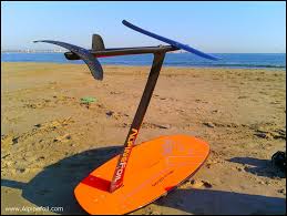
“11”,”916787″,”8″,”Stevenson SportFoiler Published||916787″,”Stevenson Projects produced a set of plans for the SportFoiler, a single person surface-piercing hydrofoil. Unfortunately, several years ago they abruptly discontinued the plans, although many of us have asked for them.

To my delight, Stevenson Products has published the plans (for free!!) online. The address is: http://www.stevproj.com/TheSportfoilPlans.pdf

I want to thank the people at Stevenson, as this project shows just how easy hydrofoils are to build. Don’t dismiss these plans. “,”2005-10-19″,”Barry Steele”,”nopswd”,” “,” “,”8”

“12”,”912432″,”8″,”Re; Re; Volga with tailfins?||912432″,”Thank you for your help, Eje! I should have found those pictures myself of course…”,”2005-10-12″,”Maurits”,”nopswd”,” “,” “,”911712”

“13”,”911712″,”8″,”Re; Volga with tailfins?||911712″,”The fins are probably original. They can be seen on several early pictures of Volgas and also on the enclosed GA.

Example from web:
http://www.seatech.ru/eng/hydrofoils.htm

Eje F”,”2005-10-11″,”Eje Flodstrom”,”nopswd”,” “,”eje_flodstrom@yahoo.com”,”910610″

“14”,”911031″,”8″,”Re; Re; Volga with tailfins?||911031″,”Mike, there is a metal plate on the hull between where the hinges of the bonnet are attached with details about year and factory number. Can’t miss it!

I saw the pictures in your ad on iboats.com, very nice looking boat! Your boat is the only other Volga that I have seen that has protective ‘bumpers’ for the aft foils (above the waterline). Is this specific for the earlier models? Or perhaps this is sort of a signature of the factory where it was made?”,”2005-10-10″,”Maurits Schornagel”,”nopswd”,” “,” “,”910659”

“15”,”910682″,”8″,”Re; Re; Volga with tailfins?||910682″,”Where is it located and what would be the asking price?

tnanks, “,”2005-10-10″,”peter”,”nopswd”,” “,”pemba1999@hotmail.com”,”910659″

“16”,”910659″,”8″,”Re; Volga with tailfins?||910659″,”I am curious about who is selling this boat and where you will use it.Where do you find them? Never seen one with fins. Can you tell me where the Volga hull ID plate are mounted? I haven’t searched mine but would like that info. If you know of anyone who might like a very nicely converted to mahogany/teak/leather/race built 454 w/V drive mid 70’s Volga on trailer,send them my way. I have many images and printed photos and am eager to sell. Boat has seen fresh water only, stored indoors for the past 5 years.

Thanks

Mike Turner

802 863 9853 p
802 863 8829 f

“,”2005-10-10″,”Mike Turner”,”nopswd”,” “,”mc27@adelphia.net”,”910610″

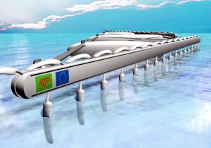
“17”,”910610″,”8″,”Volga with tailfins?||910610″,”
I am about to buy a 1965 Volga which has tailfins. None of the Volga’s that I have seen so far had such wings, so I am wondering if anyone knows if these wings are original or if they are added by a previous owner. The boat supposedly is an export version Volga; manufacturer number: 356.

Here are 2 pictures of the fins:

and

Any info greatly appreciated!”,”2005-10-10″,”Maurits Schornagel”,”nopswd”,” “,” “,”8”

“18”,”891019″,”8″,”Re; Re; Re; houseboat||891019″,”Hi Doug, the photo/sketch you provided was so large it is difficult to view on the typical computer monitor. I have reduced its size and attached it to this reply, so hopefully it will be easier to see in full!”,”2005-09-08″,”Barney C Black”,”poopdeck”,” “,” “,”886275”

“19”,”886509″,”8″,”Re; To build solar driver hydro boat||886509″,”Further to Barney’s reply, another option would be to keep ears open for news of any solar boat race event that may be held in your area and try to attend that. In the USA one such event is called ‘Solar Splash’ and one man solar hydrofoil craft have been entered into that competition. There have also been some particularly well designed and built solar and human powered hydrofoils entered in similar races in Japan. A craft named “Soland” is an example. See the photo of this in our photo gallery. The teams may be prepared to offer design tips to other prospective builders of such craft.”,”2005-09-01″,”Martin Grimm”,”nopswd”,” “,”seaflite@alphalink.com.au”,”879513″

“20”,”886275″,”8″,”Re; Re; houseboat||886275″,”thank you for your reply. As you can see I am a novice at this and do not want to get into any thing to technical.

I was thiking of adding two hinged plates 12″ wide x 3’long part way back (see atached)and adjust them manually until I get the proper position.

Going at low speed ( 4 or 5 miles a hour)would this be of any effect to raise the bow of the boat.

Or would it be easier just to use weight in the stern.

My email address is doug028@sympatico.ca

Thanks

Doug”,”2005-08-31″,”Doug Watson”,”nopswd”,” “,”doug028@sympatico.ca”,”886131″

“21”,”886131″,”8″,”Re; houseboat||886131″,”A planing surface added to each bow 5″ below the water line with a few degrees positive angle of attack at rest (depending on the hump behavior of the boat) might be the simplest solution. A hydrofoil foil may also work but one should be aware of the positive feedback effect of lift on angle of attack and thus lift using a foil on the bow and fixing the stern in the water. “,”2005-08-31″,”Harry Larsen”,”nopswd”,” “,”htdr.larsen@verizon.net”,”885742″

“22”,”886056″,”8″,”Re; houseboat||886056″,”Doug,

Not knowing how fast you go it’s hard to think about a lifting foil to alter trim. Can you reposition weights to alter trim? Have you tried a larger rudder(s) or is it a stern drive? Bow rudders have been used in the past for race boats. Perhaps bilge keels aft might help keep the stern on track, overcoming the snake wake syndrome. It sounds like your hull has inherent design problems that won’t be easily overcome unless you alter trim to reduce lateral area forward. Where is the center of lateral plane relative to midships? A steel hull is easily altered so you might consider hiring a designer to reshape your underbody.”,”2005-08-31″,”Mike Turner”,”nopswd”,” “,”mike@turnermarinegroup.com”,”885742″

“23”,”885742″,”8″,”houseboat||885742″,”I am the owner of a 33′ Georgian Steel housecruiser. The boat wants to steer from the bow. This makes the boat difficult to steer. It wanders down the lake never going straight. I was wondering if there is a type foil similar to tim tabs that can be added to the front portion of the boat. I would only need the bow raised 4 or 5 inches. I could accomplice the same by adding weight to the back of the boat but this would reduce fuel efficiency. The boat is 33′ long 12′ wide and weighs appox. 7 tons “,”2005-08-30″,”Doug Watson”,”susie-q1″,” “,”doug028@sympatico.ca”,”8″

“24”,”884504″,”8″,”Re; Bi-Directional Hydrofoil!?||884504″,”Luke,

Can you explain why you need to be able to operate a hydrofoil in both directions?

The profiles of marine propellers are hydrofoil sections. In the case of transverse or tunnel thrusters on ships, the propellers that are fitted in the tunnel are typically both symmetrical and bi-directional because the propeller must be able to to rotate both in a clockwise and anti-clockwise such that they can generate thrust to both the port and starboard side. My understanding is that the blade profile often in this case is a very flat ellipse.”,”2005-08-28″,”Martin Grimm”,”nopswd”,” “,”seaflite@alphalink.com.au”,”882034″

“25”,”882764″,”8″,”Re; To build solar driver hydro boat||882764″,”I wish I could say that the plans you want are available on the mass market and that all you have to do is order them, but that is not the case, unfortunately. The closest thing I can think of to what you are asking for is an experimental craft by the Back Yard Yacht Club. It was called the Interflight Hydroflier. Scroll down the page at http://www.stevproj.com/Carz/XBoats2.html to see photos and description. Unfortunately BYYC never got it fully developed to the point that they could offer plans for sale. BYYC did sell plans for the Sportfoil, which was a more conventional, motorboat style hydrofoil, but they sold out of the plans and did not reprint them. I have been thinking that most of the people who bought those plans probably never used them, so I have been keeping an eye out for them on the eBay auction site, but so far no trace of them.
“,”2005-08-24″,”Barney C Black”,”poopdeck”,” “,” “,”879513”

“26”,”882350″,”8″,”Re; Bi-Directional Hydrofoil!?||882350″,”A foil section that is flat on the bottom and a circular arc on the top is called “ogive”. In the level attitude, it is the same forward or reverse.”,”2005-08-24″,”Mac Stevens”,”nopswd”,” “,”stevensm@earthlink.net”,”881400″

“27”,”882034″,”8″,”Re; Re; Bi-Directional Hydrofoil!?||882034″,”Thank You for your response!!! I would like to make a man operated hydrofoil. So if the angel of attack could be manual operated, would it then be possible??? Also, would a symetrical foil even work??? at all??? Thanks!!!!”,”2005-08-23″,”Luke Miller”,”nopswd”,” “,”lewkmiller@gmail.com”,”881825″

“28”,”881825″,”8″,”Re; Bi-Directional Hydrofoil!?||881825″,”Great, since most of us don’t know if we are coming or going. Seriously,I have never heard of one and if you are talking about forward and backward it would require a symmetrical foil with an adjustable angle of attack. not too efficient. Respy, NAT K Text Text “,”2005-08-23″,”NAT KOBITZ”,”nopswd”,” “,”kobitzn@ctc.com”,”881400″

“29”,”881400″,”8″,”Bi-Directional Hydrofoil!?||881400″,”Does anybody know if there is a design for a bi-directional hydrofoil??? Any thoughts or comments would help!”,”2005-08-22″,”Luke”,”nopswd”,” “,”lewkmiller@gmail.com”,”8″

“30”,”879513″,”8″,”To build solar driver hydro boat||879513″,”I am at present looking to build a solar driven one man hydro boat,eithr in kit form or from plans.Any help would be appreciated.
fhilg”,”2005-08-18″,”phil”,”nopswd”,” “,”fhilg@hotmail.com”,”8″

“31”,”875290″,”8″,”Multi-pitch prop||875290″,”Someone had asked me in the past for a source for variable-pitch props. Land & Sea makes a series of props which automatically change pitch, from 13″ pitch continuously variable as much as 32″ pitch. This gives the bite to get the boat up on foils while still allowing top speed without over-reving the engine. Here is their link: http://www.land-and-sea.com/marine/torque-shift/torque-shift.htm”,”2005-08-10″,”Barry Steele”,”nopswd”,” “,” “,”8”

“32”,”862460″,”8″,”Re; Where is Nixons hydrofoil?||862460″,”Your question is timely. As it happens, Nixon’s hydrofoil (according to the listing) is for sale on eBay.com, with a starting bid of USD 10.000. There are several good photos with the listing. The item number is 4563069998. People with their eBay Favorite Search function set to “hydrofoil” will not find it, because this word is misspelled “hydrafoil” throughout.

Here is the text of the listing:
This one of a kind boat was a gift from Soviet Premier Brezhnev to President Nixon. The boat was given to Nixon during his 1972 visit to the Black Sea port city of Batumi, Georgia, U.S.S.R. in 1972. After a tour of the U.S. the boat was put into use by the U.S. Fish and Wildlife service to combat poaching. In 1982 the boat became surplus property and was obtained by the city of Ogallala and subsequently the Ogallala / Keith County Chamber of Commerce where is has been used for promotion of the Lake McConaughy area. I serve as President of the Chamber and our Board has decided that the craft is under-utilized so we are offering it to the highest bidder.
This aluminum boat is 28 feet long and is powered by a 90 horsepower Volvo diesel engine. At approximately 7 miles per hour the front hydrofoil takes effect and the bow of the boat rises out of water. At about 25 miles per hour the rear of the boat lifts up and the boat rides upon the water wings. Top speed is approximately 50 miles per hour. The boat has not been run in the water since the mid 1980’s. One of the photographs shows the boat running in Lake McConaughy.

The mechanical and cosmetic condition of the boat is as follows:

HULL: The hull appears to be dent and corrosion free. There may be very small scratches. No obvious defects were found during the last inspection. The foils are also in excellent condition. Some hatch cover latches need minor repair and one hinge on the engine shroud is slightly damaged. See photographs.

DRIVETRAIN: The Volvo Penta engine is complete but it is not known whether it is in running order. The engine bay has been kept dry due to a the tight fitting engine cover and the well maintained and custom fitting tarp.

INTERIOR AND TARP: These items were all refurbished in the last five years and are in excellent condition. One or two snaps on the tarp may need replaced. All gauges an switches are complete and the plexiglass windshield is undamaged.

TRAILER: As you can imagine, such a unique boat requires a unique trailer. The boat resides on a custom-built triple-axle trailer. The condition is good, however, it is recommended that the bearings be packed and the tires inspected / replaced before any long haul was attempted.

More information and additional photographs are available at the Ogallala / Keith County Chamber of Commerce website. Go to www.visitogallala.com/viktoria/htm
“,”2005-07-18″,”Barney C Black”,”nopswd”,” “,” “,”0”

“33”,”856443″,”8″,”Re; Hydrofoils for 12 foot boat||856443″,”I’ve got 3 sets of plans for home-made foils for a boat that size. Email me and I’ll give you the link. (No cost.) barry_steele@yahoo.com”,”2005-07-06″,”Barry Steele”,”nopswd”,” “,” “,”0”

“34”,”856328″,”8″,”Hydrofoils for 12 foot boat||856328″,”I’d like to put hydrofoils onto a 12′ long aluminium motor boat, for use mainly on rivers. Does anyone know where I’d find information on what configuration/design of foils/foil profiles I should use?

Regards, Roland”,”2005-07-06″,”Roland Wilson”,”nopswd”,” “,”r.wilson@bath.ac.uk”,”0″

“35”,”855802″,”8″,”Re; Where is Nixons hydrofoil?||855802″,”I don’t know where it is, but it was a small eight seat hydrofoil
“,”2005-07-04″,”Umi_Ryuzuki”,”nopswd”,” “,”umi_ryuzuki@hotmail.com”,”0″

“36”,”855682″,”8″,”Where is Nixons hydrofoil?||855682″,”I heard that the Russian president Brezhnev gave Nixon a hydrofoil in 1974. I was wondering if anyone knew where it is and anything about it. I know that it was a Volga-70, but I’d like to know more details about it.”,”2005-07-04″,”Vladimir”,”nopswd”,” “,”Philipok1476@aol.com”,”0″

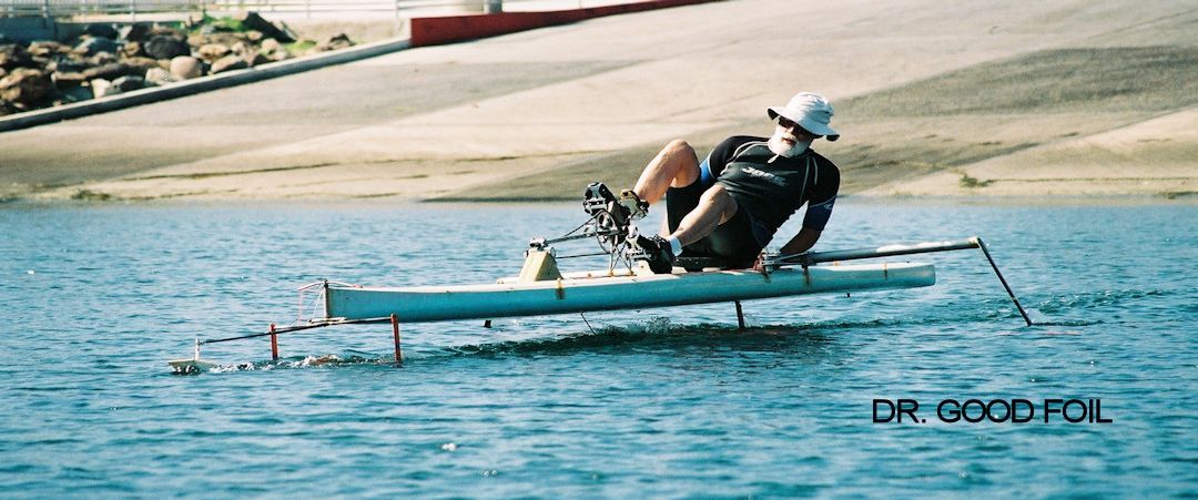
“37”,”855325″,”8″,”Need David Keipers Book plus Hyfibe Pics||855325″,”You may remember me from a few years back when you referred me to an owner of Keiper hydrofoil extrusions. I bought those extrusions and have had some success in incorporating them into my Hyfibe (high flying banana). A picture is attached.

At this time, I am trying to acquire a copy of David’s book. I attempted to purchase a hard copy on Ebay and after being on their waiting list for about a year, I gave up. The IHS show that some of you may have a scanned electronic version of it.

If you have such a copy, could you please reply to me or tell me how I could otherwise obtain one.
Thanks,

Ray Vellinga

“,”2005-07-03″,”william white”,”nopswd”,” “,”whitewn@speakeasy.net”,”0″

“38”,”852895″,”8″,”Re; Re; Volgas of today||852895″,”I’d love to see your volga pictures. You can easily post many of them on a free Geocities website, or I’d be happy to do it for you. They allow 15Mb for free. Email me barry_steele@yahoo.com”,”2005-06-29″,”Barry Steele”,”nopswd”,” “,” “,”0”

“39”,”852528″,”8″,”Re; Volgas of today||852528″,”Jan,

I have many photos of this mighty hydrofoil speedboat. Probably too many to post here but see the few enclosed and let me know what kind you would like me to send you on a CD. Send an address for ground mail if possible.

cheer>> Mike Turner

“,”2005-06-28″,”Mike Turner”,”nopswd”,” “,”mike@turnermarinegroup.com”,”0″

“40”,”847775″,”8″,”Volgas of today||847775″,”Hello DAN WETTWEILER and MIKE TURNER.
Please send me some info and photos of your Volgas.
I try to keep some track of the Volgas in Sweden and have
establihed contacts all over Europe. I have a feeling
the interest for Volgas is now growing over here.
Enclosed I send some of the pictures I have accumulated
last few years. I myself have a Volga from 1984 with
the russian V-drive – not Volvo.
Best regards to you and all Volga fans in IHS.
Jan Wennerstrom volga.stockholm@bredband.net”,”2005-06-18″,”Jan Wennerstrom”,”nopswd”,” “,”jan.wennerstrom@bredband.net”,”0″

“41”,”845084″,”8″,”Re; For Sale||845084″,”Hi Dan,

I have a Volga 70 also and would love to sell it – too many boats .
What are you asking for and do you have any emailable pictures? If so please direct me to them.
When and how did you aquire the boat? Mine is the converted turquoise beauty with 454 V8 and straight shaft seen on eglobalyachts.com under Vermont boats or custom hydrofoil under 30′.
Good luck with your effort.
Mike Turner”,”2005-06-13″,”Mike Turner”,”nopswd”,” “,”mike@turnermarinegroup.com”,”0″

“42”,”844851″,”8″,”For Sale||844851″,”Volga 70 Hydrofoil, Volvo diesel engine & 270 leg,all in exellant condition,moored boathouse .Selling as I am 85.Location British Columbia,Canada.Contact, daniel_dettwiler@telus.net”,”2005-06-12″,”Dan Dettwiler”,”nopswd”,” “,”Daniel_Dettwiler@telus.net”,”0″

“43”,”844512″,”8″,”Re; Re; Dynafoil Movie Online!||844512″,”excellent clips of you doing the Dynafoil equivalent of wheelies. Thanks for sharing this…”,”2005-06-11″,”Barney C Black”,”poopdeck”,” “,” “,”0”

“44”,”844090″,”8″,”Re; Re; Dynafoil Movie Online!||844090″,”Here’s the famous Dynafoil wipe-out. Just so you know, no Dynafoils were injured during the making of this movie!

http://blondiesmachinery.com/mov/todd2.mpg”,”2005-06-10″,”Todd Miller”,”nopswd”,” “,”austinado16@cs.com”,”0″

“45”,”840806″,”8″,”Re; Dynafoil Movie Online!||840806″,”BJ’s posted another one for me! Here’s the url:
http://blondiesmachinery.com/mov/todd1.mpg

I’ve got a great Dynafoil wipeout to share as well, so maybe that will be up in the near future.”,”2005-06-04″,”Todd Miller”,”nopswd”,” “,”austinado16@cs.com”,”0″

“46”,”837515″,”8″,”Dynafoil Movie Online!||837515″,”Hello Dynafoil Lovers!
I have the first of hopefully many Dynafoil movies posted to the www. Here’s the address: http://blondiesmachinery.com/mov/todd.mpg

Thanks to my brother Tori for running the digital camera from his boat, and to BJ Meinhardt for posting it to the web!”,”2005-05-29″,”Todd Miller”,”nopswd”,” “,”austinado16@cs.com”,”0″

“47”,”836368″,”8″,”jetski/personal watercraft to a hydrofoil?||836368″,”I’ve got a wetbike for sale as well. We can fix you right up! Seneca, SC. barry_steele@yahoo.com”,”2005-05-27″,”Barry Steele”,”nopswd”,” “,” “,”0”

“48”,”835751″,”8″,”jetski/personal watercraft to a hydrofoil?||835751″,”Terry, I have a couple Wetbikes for sale….. Instant jet propelled hydrofoil : )

TORI
tjm52071@sbcglobal.net”,”2005-05-26″,”TORI”,”nopswd”,” “,”tjm52071@sbcglobal.net”,”0″

“49”,”812753″,”8″,”Re; Re; Searching 4 a dynafoil||812753″,”Hey Josh, let me know when you get one of your engine powered kayaks up to 63 mph, then I’ll be impressed. Meantime we’ll keep trying to find a Dynafoil for you. Maybe I can find a surplus turboshaft to put in it for you. 🙂
“,”2005-04-13″,”Scott Smith”,”nopswd”,” “,”ssmith@veinrxinc.com”,”0″

“50”,”810638″,”8″,”Re; Re; Searching 4 a dynafoil||810638″,”Oh that really hurt. Todd you’ve insulted me for the last time. I guess in the mean time the ultra 150 will have to mess up my pretty hair. 63mph on radar aint to shabby for a stock ski. Getting back to the subject of the dynafoil, YES I still want one. Maybe more than one.


“,”2005-04-09″,”josh”,”nopswd”,” “,”josh977@hotmail.com”,”0″

“51”,”810353″,”8″,”Re; Searching 4 a dynafoil||810353″,”Don’t anybody sell Josh a Dynafoil. All he’s gonna do is take it out on the lake, get it all wet, mess up his hair, and wind up with an aching face from smiling so much.”,”2005-04-08″,”Todd Miller”,”nopswd”,” “,”austinado16@cs.com”,”0″

“52”,”810086″,”8″,”Re; want to buy……..||810086″,”I haven’t built them yet, but I knew some who did, and liked them. They are simple to build and would work for a wide range of hull weights and sizes. I plan to make a set in a few months, as well as making modifications to the plans. I’ll send you the plans if you drop me an e-mail, much easier to send them that way, they are in PDF format. You can reach me at ssmith@veinrxinc.com.

Scott”,”2005-04-08″,”Scott Smith”,”nopswd”,” “,”ssmith@veinrxinc.com”,”0″

“53”,”809698″,”8″,”Searching 4 a dynafoil||809698″,”I’ve been looking for months with little or no success in locating a dynafoil. I’ve been in touch with Todd Miller and Sctt Smith. These two have been extremely helpful in answering my slew of questions. Email if you have any info on a dynafoil for sale.

thanks, Josh “,”2005-04-07″,”josh jensen”,”nopswd”,” “,”Josh977@hotmail.com”,”0″

“54”,”809122″,”8″,”Re; want to buy……..||809122″,”Scott,

Thanks sfor the idea. Please forward the plans if you can and I will look them over. Did you build one?
Brad Lucas
3505 Ramblin Creek
Lou. Ky 40299
“,”2005-04-07″,”Brad Lucas”,”nopswd”,” “,”demokim2@insightbb.com”,”0″

“55”,”799205″,”8″,”Dynafoil Parts and Service Manual available||799205″,”In case my email address doesn’t print out, it’s: austinado16@cs.com”,”2005-03-19″,”Todd Miller”,”nopswd”,” “,”austinado16@cs.com”,”0″

“56”,”799204″,”8″,”Dynafoil Parts and Service Manual available||799204″,”In case my email address doesn’t print out, it’s: austinado16@cs.com”,”2005-03-19″,”Todd Miller”,”nopswd”,” “,”austinado16@cs.com”,”0″

“57”,”799201″,”8″,”Dynafoil Parts and Service Manual available||799201″,”Hello Dynafoil fans,
Thanks to Russell Autry in Harriet, Arkansas I know have an original Dynafoil Dealer Parts and Service Manual. It’s dated 1976 and contains updates from 1977. It also contains the dealer pre-purchase assembly, delivery and inspection/preparation information, along with warranty and claims submital info. Very cool! If that’s not enough, it also has a color Walbro carburetor manual.

I’ve made 8 copies of it and went to great effort and expense to find a copy machine capable of reproducing the nice black and white photographs. So, the pages look great, as do the photos. I had the Walbro manual redone in color also. These are assembled in black 3-ring binders, with the blue “section” dividers just like the original.

They are running about $34.00 including US Priority Mail shipping in the US. I’m happy to send them to other countries for the additional shipping charges (maybe another $10-$15, but that’s just a guess).

Send me an email if you’re interested, I still have 4 copies left. But when those are gone, I’ll be glad to make more.”,”2005-03-19″,”Todd Miller”,”nopswd”,” “,”austinado16@cs.com”,”0″

“58”,”798691″,”8″,”Re; I`ll transfer his video to DVD||798691″,”Thanks for that kind offer! I just got the 8mm projector and movie about 2 weeks ago and Scott Smith was kind enough to send me his 8mm movie as well. Unfortunately, Scott’s movie is the same as mine. They are dealer demo movies about 5 minutes long.

I’ve found a local place that will do the transfer and color correction “in house” and put it onto a digital tape format. From there, they will burn DVD’s.

I’ll make them available as soon as I get them.

It would be fun to go shoot some footage of ours in action, and add it to the original footage. Sort of a “then and now” theme!
Todd”,”2005-03-18″,”Todd Miller”,”nopswd”,” “,”austinado16@cs.com”,”0″

“59”,”798305″,”8″,”looking for sportfish hydrofoil- pleasure||798305″,”A yacht quality line of semi custom and custom sportfish hydrofoil supported catamarans called Fincat is designed by Viking Fast Craft Solutions, www.vikingfastcraft.com and built by Parker Marine in Biloxi Mississippi. www.fincatcatamarans.com “,”2005-03-18″,”B. Smith”,”nopswd”,” “,”vikingfcs@cableone.net”,”0″

“60”,”792116″,”8″,”Plans for 2-man Hydrofoils||792116″,”If you (or anyone else) want me to email copies of some published plans for 1-2 man home-made hydrofoil boats, please email me at barry_steele@yahoo.com Overall, they occupy about 6 megabytes, so please ensure you have space in your mailbox.”,”2005-03-07″,”Barry Steele”,”nopswd”,” “,”bsteele971@hotmail.com”,”0″

“61”,”791923″,”8″,”jetski/personal watercraft to a hydrofoil?||791923″,”Barry,

These plans should be of interest to other members of IHS. If you could mail a copy of each plan to me I will have them scanned and made into an appropriate digital file and emailed to IHS for posting on their web site for all to see. The plans would then be returned to you. Contact me at rvell@san.rr.com and I will email you my address.

Ray Vellinga
“,”2005-03-06″,”Ray Vellinga”,”nopswd”,” “,”rvell@san.rr.com”,”0″

“62”,”791575″,”8″,”jetski/personal watercraft to a hydrofoil?||791575″,”thanks for the info Barry. im not really sure how to send you an email but if you get this msg, my email address is t.enzweiler@comcast.net

thanks again
Terry”,”2005-03-06″,”Terry Enzweiler”,”nopswd”,” “,”t.enzweiler@comcast.net”,”0″

“63”,”791250″,”8″,”jetski/personal watercraft to a hydrofoil?||791250″,”I have a lot of jet ski experience, but haven’t put foils under any of them. I think that the biggest trick is to extend the water pickup for the jet pump without restricting the flow; resulting in cavitation in the jet pump. You also asked for a towable foil; I have 3 different sets of 1-2 man hydrofoil boat plans I’d gladly email to you. I’m sure they would be towable and can easily be adapted and scaled for other applications. Email me.”,”2005-03-05″,”Barry Steele”,”nopswd”,” “,”barry_steele@yahoo.com”,”0″

“64”,”791061″,”8″,”jetski/personal watercraft to a hydrofoil?||791061″,”I have some questions with regards to hydrofoils and am looking for someone with some knowledge about them. i only know a little something about jetskis and not much beyond that.

Can anyone who could answer these questions?

1. can you convert a jetski/personal watercraft to a hydrofoil?

2. do you know someone who could build a hydrofoil i could tow behind a jetski/personal watercraft?

any info you have would be appreciated

Terry Enzweiler”,”2005-03-04″,”Terry Enzweiler”,”nopswd”,” “,”t.enzweiler@comcast.net”,”0″

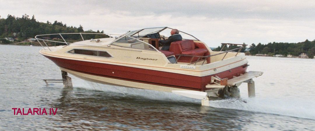
“65”,”790620″,”8″,”Hydrofoil Fishing Boat ||790620″,”Suggest you take a look at this video of Harry Larsen’s TALARIA III (14 seconds, 2 megabites:
http://mysite.verizon.net/res6pe7p/talaria.mpg

This boat is not in production, but you could buy Harry’s boat, or if you want more luxury, hire Harry to help you convert the boat of your choice. There is a parts list with prices at:
http://mysite.verizon.net/res6pe7p/indexPartsList.htm

The main web page is at:
http://mysite.verizon.net/res6pe7p/

I see that for the still photos on this page, the thumbnails are not showing up, just an empty box. However, if you click on the box, the full size photo will in fact appear on your screen.

This boat was featured in a History Channel program about hydrofoils.”,”2005-03-04″,”Barney C Black”,”poopdeck”,” “,”barney@alum.mit.edu”,”0″

“66”,”785170″,”8″,”sportfish foil||785170″,”i am the marine consultant for a current pro basket ball player in the s.e. u.s.. i am looking for a 40′-60′ hydrofoil with a sportfish-style fishing cockpit and yacht interior. prices, pix (no drawings), specs a must.”,”2005-02-21″,”harlan trammell”,”nopswd”,” “,”bigpineartifacts@yahoo.com”,”0″

“67”,”783825″,”8″,”Re: want to buy……..||783825″,”I have plans for simple wooden foils that you can build yourself and attach to a small runabout. They were first printed in Popular Science a long time ago. If you would like them (free) contact me and I’ll send them along.”,”2005-02-18″,”Scott Smith”,”nopswd”,” “,”ssmith@veinrxinc.com”,”0″

“68”,”780296″,”8″,”WTB: Dynafoil||780296″,”I’m looking for a Dynafoil in any condition in the lower 48 states. Please contact larry skagitmedia com “,”2005-02-11″,”Larry”,”nopswd”,” “,”larry@skagitmedia.com “,”0”

“69”,”780083″,”8″,”I’ll transfer his video to DVD||780083″,”I’d be more than happy to transfer Todd Miller’s Dynafoil video to DVD. I’d gladly do it for free, and if he wants multiple copies, make them for cheap. I’d just like to see it myself.”,”2005-02-11″,”Barry Steele”,”nopswd”,” “,”bsteele971@hotmail.com”,”0″

“70”,”779947″,”8″,”Web site||779947″,”My web page address is:
http://mysite.verizon.net/res6pe7p/
The web address on the IHS page (Hydrofoils Around the World) that doesn’t work is:
http://mysite.verizon.net/res6pe7p/index.htm
“,”2005-02-11″,”Harry Larsen”,”nopswd”,” “,”htdr.larsen@verizon.net”,”0″

“71”,”779667″,”8″,”Re: looking for sportfish hydrofoil- pleasure||779667″,”The only one I know of domestically (USA) is Harry Larsen’s Bayliner… looks like he dropped or moved his website. He has a posting elsewhere on the BBS. I have seen some new Russian models advertised on the internet but cannot vouch for them. “,”2005-02-10″,”Barney C Black”,”poopdeck”,” “,”bcblack@erols.com”,”0″

“72”,”779660″,”8″,”Re: More Dynafoils located!||779660″,”most interesting… suggest that the movie be transferred to DVD, and copies offered for sale on eBay!”,”2005-02-10″,”Barney C Black”,”poopdeck”,” “,”bcblack@erols.com”,”0″

“73”,”779525″,”8″,”looking for sportfish hydrofoil- pleasure||779525″,”am doing marine consulting for current, u.s. pro basketball player looking for a custom hydrofoil in a sportfish configuraion for sale. all info on manufacturers and prices appreciated”,”2005-02-10″,”harlan trammell”,”nopswd”,” “,”bigpineartifacts@yahoo.com “,”0”

“74”,”776082″,”8″,”More Dynafoils located!||776082″,”Hi All,
Just wanted to share a neat Dynafoil find. Russell Autry in Arkansas recently discovered a 1978 Dynafoil sitting in the bushes of his boss’s residence. It’s trailer has also been found. But this isn’t the real story. Russell went online in search of parts and posted a “wanted” message on a watercraft website.

Soon after, he was contacted by a guy in Alabama who 2 of them for sale along with their original double trailer, along with a large number of NOS parts, a factory service manual, and…jackpot…a Dynafoil Dealership movie projector with a Dynafoil Demonstration movie inside!

The boats are sisters, #492 and #493 built in June of 1979. Russell and former Dynafoil owner Al Hayes (in Tennesse) have purchased the whole shabang, and although the boats are no longer a pair, they are at least going to be saved and restored.

Todd

“,”2005-02-04″,”Todd Miller”,”nopswd”,” “,”******************”,”0″

“75”,”763300″,”8″,”Tracking the remaining Dynafoils||763300″,”Hello Dynafoil fans!
I’ve been working on figuring out how to read the Hull Identifcation Numbers (HIN’s) on the Dynafoils. Thanks to fellow Dynafoil owners BJ Meinhardt (http://www.ussaries.org/dyna/dyna.html) and Scott Smith, I think I’ve got it. Although, I’m still not completely clear on the 1974-1975 HIN’s, I do understand the 1976-1980’s.

Any help on the 1974-1975’s would be greatly appreciated!

I’ve started a table on the “Hull ID Numbers” page of my website (www.dynafoil.com) so that we can keep track of the remaining Dynafoils and see what numbers are left. This has turned out to be pretty interesting because Scott Smith has a very late one, and possibly one of the very last….#527, built in 1980. He also has #306, and I own #308!! Our boats were sitting there nearly side-by-side and now they are on opposite coasts.

Anyway, it would be great if some of you Dynafoil owners would contribute your Hull numbers so we could add them to the table. I’ve also started an “Owner’s” page and a “Memories” page so feel free to contribute to those as well!

Can’t wait for warmer weather!
Todd “,”2005-01-12″,”Todd Miller”,”nopswd”,” “,”austinado16@cs.com”,”0″

“76”,”759297″,”8″,”Re: want to buy……..||759297″,”A couple of ideas… see the ads on this forum for Volga 70 runabouts offered for sale. Go to www.foils.org/popmags.htm and look for old hobbyist magazines that have plans for adding foils or building your own runabout. Then get the issue(s) that interest you by looking on eBay, the library, old magazine store, etc. Unfortunately nobody is offering new manufacture hydrofoil motor-powered runabouts that I know of. There are a couple of sailboat models, though. Good luck.”,”2005-01-04″,”Barney C Black”,”poopdeck”,” “,”barney@alum.mit.edu”,”0″

“77”,”758875″,”8″,”want to buy……..||758875″,”I am wanting to purchase plans or a 16-25 ft boat for pleasure motoring. I understand the workings of the foils. I have a air-chair which works on same idea. Looking to put foils on deck boat or pontoon. Even a small run about would be great.
Where, who, when, how.

Thanks for your help.

Brad”,”2005-01-04″,”Brad Lucas”,”nopswd”,” “,”demokim2@insightbb.com”,”0″

“78”,”756233″,”8″,”Re: VOLGA for sale||756233″,”Hi Jan, Good luck with your sale… are you selling your beautifully restored craft so that you can undertake a new project? I was just curious. For potential buyers, IHS has several photos of the VolgaVingen at the following page: //archive.foils.org/gallery/volgavi.htm. When you are on that page, click each thumbnail photo to see its large version.”,”2004-12-27″,”Barney C Black”,”poopdeck”,” “,”barney@alum.mit.edu”,”0″

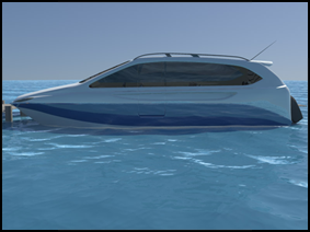
“79”,”754615″,”8″,”VOLGA for sale||754615″,”The “VolgaVingen” is for sale in Stockholm.
Nicely restored and fitted with a brand new GM 350 ci.”,”2004-12-21″,”Jan Wennerstrom”,”nopswd”,” “,”jan.wennerstrom@bredband.net”,”0″

“80”,”746560″,”8″,”Re: The Dynafoil Website is on line.||746560″,”It is a visually appealing site with lots of good info… Congratulations! And thanks for the link to the IHS site.”,”2004-12-02″,”Barney C Black”,”poopdeck”,” “,”barney@alum.mit.edu”,”0″

“81”,”744334″,”8″,”The Dynafoil Website is on line.||744334″,”Hi All,
Just wanted to let everyone know that I have created a Dynafoil website and it’s now on line at: www.dynafoil.com (catchy url isn’t it?) So please stop by and have a look. All feedback and information gladly welcomed.

I’m working on several other pages for it right now, so it will fill in nicely in the next few months.

Todd
“,”2004-11-27″,”Todd Miller”,”nopswd”,” “,”austinado16@cs.com”,”0″

“82”,”743479″,”8″,”Re: Dynafoil Update Nov 21 2004||743479″,”Hi Barney,
Thanks for the help. I’ve just sent the photo to both of those email addresses. I’ve posted photos before, so I’m not sure what the problem is.

I’m going back to the lake on Friday or Saturday, so I hope to have more photos and fun to share.

Also, I’ve just located one of the original members of the Dynafoil company, who was also one of their demonstration riders. He’s 60 now and we are planning on getting together for a trip to the lake so he can ride again. He has some great stories…..pulling skiers, running circles around Kawasaki Jet Skies that were out on the ocean in their early stages of testing too, riding to Catalina Island (26 miles) on Dynafoils, riding in the demonstration tank (3′ deep x 150’dia) at the Los Angeles County Fair Grounds, etc.

He wants to buy a Dynafoil or 2 if anyone has them to sell. Contact me.”,”2004-11-24″,”Todd Miller”,”nopswd”,” “,”austinado16@cs.com”,”0″

“83”,”743422″,”8″,”Re: Dynafoil Update Nov 21 2004||743422″,”Thanks for the update, Todd. If your photo is too large for the BBS, I suggest you email it along with accompanying text assembled from your current and past BBS postings to: gallery@foils.org and editor@foils.org.”,”2004-11-24″,”Barney C Black”,”poopdeck”,” “,”barney@alum.mit.edu”,”0″

“84”,”741640″,”8″,”Dynafoil Update Nov 21 2004||741640″,”Thought I’d give an update on my 1977 Dynafoil.

After riding it during this summer with the 340cc engine that I installed, I wasn’t happy with the performance and started looking for a 440cc engine, which is what it originally came with.

I purchased a 440 several weeks ago, installed it this past week and took the Dynafoil up to the lake today for testing.

The transformation is nothing short of amazing. It now launches itself out of the water by pulling a “wheelie” as fast as I can roll on the power. This immediatel brings the front strut and the entire hull completely out of the water and only the rear foil and prop remain submerged.

It’s an amazing craft to ride now, where before it was a lot of fun but very tame. Now it’s like riding a 1200cc sport bike.

I’ve tried to post a photo with this message, but the system says I can only post a 10byte photo……”,”2004-11-21″,”Todd Miller”,”nopswd”,” “,”austinado16@cs.com”,”0″

“85”,”741639″,”8″,”Dynafoil Update Nov 20, 2004||741639″,”I’ve had a major break through in my 1977 Dynafoil and wanted to share it here.

Some of you will remember that my brother and I found 3 of these at the local swap meet and eventually bought them, and the original double trailer that the pair of later ones came on.

Initially, I found that new old stock (NOS) 340cc Chaparral/Xenoah engines were readily available because the ultra light aircraft use so many of them. $200 for a new engine was a great deal, so even though the Dynafoil came with the 440cc version of this engine, I made the purchase.

To make a long story short, the 340 is just not capable of the performance needed to really fly the Dynafoil as it was meant to be flown. It took quite a bit of effort and patients to get the Dynafoil up to flying speed and out of the water. A few minor performance mods to the engine didn’t offer much change so I found a 440 engine and installed it this past week.

The transformation is nothing short of amazing! As fast as I can roll on the throttle, the front strut comes completely out of the water, followed immediately by the rest of the hull….to say nothing of the top speed.

Here’s a photo from today’s brief bit of testing.

“,”2004-11-21″,”Todd Miller”,”nopswd”,” “,”austinado16@cs.com”,”0″

“86”,”729200″,”8″,”volga 70 hydrofoil||729200″,”I read with great interest all the archive material on the Volga 70. I have always had a passion for all hydrofoils, so you can imagine my delight when I spotted a small tatty hydofoil while cycling on the banks of the Danube five miles from Budapest. The yard owners wanted £6000. It was, according to them, an ex Hungarian police boat with a six cylinder petrol engine of unknown origin. It was there for another thee years and getting cheaper all the time. I wanted to make an offer as it would make an interesting stablemate for my Sunseeker moored in Budapest. So I took £1500 only to find it sold for scrap the day before for £1000! I burst into tears for an hour or so.
When I arrived back in the UK I scanned the interweb and found the boat to be a Volga 70.”,”2004-10-27″,”Kevin Warner”,”nopswd”,” “,”kevin@cobra.gb.com”,”0″


This board has been viewed 21681 times since Apr-20-2002 .
(Total Views Since Board Creation on Mar-21-2002 is 22415.)


Questions about this board, email: bbs@foils.org
System Support, Email: support@bulletinboards.com

To Learn About Bulletin Boards:  Click Here
Bulletin Board Management Site: Click Here

(321) 984-9080
© 1997 – 2004 P.A. Corp. V7.1 Correspondence

Value of the Hydrofoil Industry

[12 Feb 03] I am creating a presentation on government inventions, and I was wondering if you had any numbers concerning the economic value of the hydrofoil industry. Either how much revenue is derived internationally, or anything like that which can help me out. — Kathleen Rooney (KATHLEEN.K.ROONEY@saic.com)

Cyberlife Boat Needs Math Calculations

[15 Mar 02] Well it’s gotten to the point where I am going to build a small working craft of about 7 m, but there is one problem. I cannot work out the math on the amount of power it will give (I build, design, and have a good idea how it all works) but when it comes to these sort of math, I am out of my depth. So I can calculate the weight and power of the generators etc. I have asked a few others, and nobody can give me a real opinion, as there would be a water slip factor, so the traction could be taken off. That’s the problem with new ideas. So?? do you know any member who would like to help with this problem. Please read the attached article first; it will help you understand the drawings and how it works, why, what etc. — Ken Upton (ken@ecofrogs.org)

Response…[20 Aug 02] I am not at all convinced that foils traveling in a straight line are more efficient than those rotating about a hub as in a conventional turbine. The math is simpler, that is all. The main doubt that I have is that even if the efficiency is better, the efficiency of a tidal or river turbine is not important in itself. The energy is free. That which you don’t capture is wasted anyhow. The measure of usefulness is power output per $. It seems to me that the conveyor of foils will be so much more expensive to build and maintain than a propeller that it will never compete. I do think more use should be made of renewable energy and less from fossil fuels, and if this conveyor of foils helps, that’s great. However, it has to be cheap enough to compete. Anticipate the argument that if you are trying to get power out of a river, you can get much more out if you build a dam. The reasoning is this: In a river, the water looses potential energy as it falls, and gains kinetic energy. However it never gains much kinetic energy because the friction losses build up as it gets faster, which limits the speed to about 10 mph or less in most rivers. At that speed the kinetic energy is the same as the potential energy of a 3 ft drop. So to extract more energy than you get from a 3 ft drop, you can install multiple turbines with a 3 ft vertical difference at intervals along the river, or you can build a dam. The dam slows the water down so that there is negligible friction loss along the reservoir (or it would have a slope!) so the whole drop is available in one place for big turbines. — Malin Dixon (malin@onspec.co.uk)

WIG Skeptic

[10 Mar 02] With the untimely death of John Reeves, we have lost the best authority on Wing-in-Ground-effect craft (WIG) or Ekranoplans as they are also known [Such aircraft fly very close to the water surface (typically within a chord length). This improves the lift to drag ratio of their short wings – Editor]. However, ALL of the work that the Russians did, including Ekranoplan, was deemed a failure by the study group sponsored by DARPA, several years ago. John’s work was on a completely different tack, and it offered real hope for success. I believe a Capt… Hillyer, at NAVAIR is continuing that work. WIG has too many problems in safety of flight and control to warrant serious study except in very special cases. — Nat Kobitz (KobitzN@ctcgsc.org)

Cruise Ship Photos Wanted

[10 Mar 02] I have Turkish, Japanese, Greek, American and Italian ferries photos and cruise ship photos. If you want to exchange, please write me. — Fatih Takmakli Chicago-USA (fatihtakmakli2000@yahoo.com)

Response…[10 Mar 03] IHS posts photos of hydrofoils in *.jpg formats but does not as an organization sell or exchange hard-copy photographs. There may well be individuals who as members or visitors to the site are interested in doing so, however. The Ebay auction site is a good source for such photos, especially in the form of postcards. You may also want to visit Tim Timoleon’s Classic Fast Ferries website and Konstantin Matveev’s Russian Hydrofoil site. Finally, you may want to visit the cruise ship section of http://www.usnavalships.com/ and contribute information and photos to help build the site. — Barney C. Black (Please reply via the BBS)

Foil-Based Power Generation From Tides and River Currents

[2 Sep 01] I think this will interest your members. I will join IHS soon. I am in AYRS and am just getting into hydrofoils. With reference to the attached draft design, I would like just to ask one question: What foil would give me the maximum combination of lift and drag factors working together… I think a fat camber foil . It will be only moving at 1-2 mts /second as the load factor will control the speed. This is opposite to all the uses of foils, so far as I know. Any help??? Ideas, etc. always welcome. — Ken Upton (ken@ecofrogs.org)

Responses…[11 Sep 01] It seems you may be asking what foil profile would give you a good lift-to-drag ratio or both a high lift and a high drag? What you really need to do to maximise the power input on your device is to select a foil profile, planform and angle of attack relative to your conveyor that maximises the combination of thrust and velocity of the foils (ie: Input Power = T x v). I have never really examined such an issue before and I only have a few old aerodynamics books so I can’t give you any good advice on foil profiles. — Martin Grimm (seaflite@alphalink.com.au)

[11 Sep 01] (We have had one response that your design appears workable, but your emails were brief to the point of being a bit cryptic. The respondent tried to rephrase and expand upon your inquiry according to his understanding of it, as follows. – Webmaster): I am working on developing an invention I have for a water turbine in which multiple foil units are mounted on a horizontal conveyor belt type of arrangement. This arrangement is partially immersed in the flowing water of a river such that the foils on the lower section of the conveyor belt are submerged and on the upper section they emerge from the water again. The action of the water current on the submerged foil sections causes the conveyor belt to rotate and drive a generator unit mounted at one end of the conveyor system. The conveyor may best be positioned at an angle to the flowing water such that the foils when moving around the conveyor also travel downstream while submerged (and return upstream on their return travel along the top of the conveyor). I anticipate the foils on the conveyor will only be moving at around 1-2 metres/second depending on the strength of the current. I would like to know what foil arrangement would give me the best combination of lift and drag from the foils in order to maximise the power input to the generator. I think a larch chord length cambered foil may be suitable but would welcome your advice.

Hovercraft Skirts

[12 May 01] I would like to know where you can purchase hover craft skirts, or designs on skirt designs and what they are made of. — Adrian Hibbard (hibbard_adrian@hotmail.co.nz)

Response…[12 May 01, updated 3 Nov 02] A good place to start is at The Hovercraft Cruising Club (THCC) whose purpose is to provide a common location to find information for all those interested in hovercraft cruising. Their Web address is www.hovercruiser.net/. [This site has dropped off the web. If anyone knows its new location, please notify the IHS webmaster!] Also checkout the website of the Hoverclub of America. Whether your interests lie in Constructing, Cruising or Competing your source for Hovercraft information. Their Web address is http://www.hoverclubofamerica.org/.

Mitsubishi RAINBOW Lessons Learned

[18 Jan 01] Just a quick note to let you know that Mitsubishi is giving a paper on its experiences with the fully submerged hydrofoil catamaran, RAINBOW at the Fast Ferry Conference in New Orleans, 13th – 15th March. The second diesel driven fully submerged hydrofoil catamaran RAINBOW 2 operated by the company, entered service in 1998 following the 5 year operation of its sister vessel RAINBOW. The paper looks at the trials and tribulations of bringing both craft into service and how the technical upgrading of both craft allowed the pair to run a technically free service from 1999 – 2000. If you want to know more about the 17th Fast Ferry Conference & Exhibition, either drop me a line or go to the website and click on the conference logo at the bottom of the page. — Giles Clark (info@fastferry.org); Fast Ferry Conference & Exhibition; 4midable Ltd; Windmill Oast; Beneden Road; Rolvenden, Cranbrook, Kent TN17 4PF; Tel: +44 1580 240055; Fax: +44 1580 240066; website: www.4midable.net

New Site Devoted to Ekranoplans (WIG) Craft

[2 Dec 00] The Center of Ekranoplan Technologies (ALSIN) has a website with detailed info on WIGs including a small ekranoplan AQUAGLIDE, an achievement in aircraft and shipbuilding that can glide above water, snow and land in all climatic zones, all weather with speed up to 170 km/h. The Center has other developments in this field with information on the website.at field which You would be interested in organizing new tourist lines. — ALSIN email: (aquaglide@mtu-net.ru)

4th Generation Cruiser Plans?

[10 Nov 00] Hi, I am a professional 3D modeler-animator, and I’m looking for some blueprints, diagrams or any schematics for a 4th generation cruiser boat, to construct it in 3D for a project. What I’m looking for is a turistic cruiser, those that operates with a crew of 3000 to 5000 and about 3000 passengers, and travels in the Caribbean region. I’ve been told those are “4th Generation” vessels, white and big. Do you remember “Love Boat”, well, the new ones are twice the size, and I need blue prints, since I’m building it in 3D software. — Fernando Gonzalez S. (email: digitalshop@spin.com.mx) ( website: www.digitalshopfx.com)

Response…[10 Nov 00] You may be thinking of a project that was called ‘Phoenix World City’ – a huge ship for floating conventions with three hotel-size superstructures and about 1200 feet long. Not sure if the project is still being pursued, but at one time Title XI loan guarantees were being sought from MARAD (U. S. Maritime Administration). — Mark Bebar (bebar@foils.org)

[10 Nov 00] See also the Seascape website at http://www.seascape1.com/ – Barney C Black (Please reply via the BBS)

Submerged Turbojet Designs

[13 Oct 00] Looking for all info/patent abstracts on fully-submerged Turbojet(s) that have be intergrated into hydrofoil designs. I am an investor who has been approached to become involved in a project. Your site is great! — Louis Parker (LouisLFP@worldnet.att.net)

Responses…[13 Oct 00] –Turbojets are everywhere. If you are implying turbojet engines, 43 years ago I worked on and tested an underwater ramjet in a submerged foil. Worked fine, but like other ramjets needed a different means to start up. We tried ejectors with marginal success. I don’t know of any recent work. Maybe this message will wake some memories in the IHS members. — Nat Kobitz (KobitzN@ctc.com)

[13 Oct 00] I am not sure how to interpret this request. Are you making a reference to waterjet units that are fully submerged? Of course there have been several waterjet propelled hydrofoils built over the years, namely the Patrol Hydrofoil Missile (PHM) and the Jet Foil. These actually only have the waterjet intake ducting submerged and the waterjet impeller (or pump) is mounted in the hull above the foilborne waterline. The water emerging from the waterjet impeller is simply expelled out of the back of the foilborne hydrofoil through a nozzle well above the waterline. I vaguely recall seeing a French hydrofoil concept (possibly in Jane’s Surface Skimmers of around the mid 70’s?) which featured what appeared to be almost like a submerged waterjet unit mounted at the intersection of the rear foil and its support strut. If on the other hand ‘Turbojet’ is a reference to a gas turbine engine, there are also such units driving a range of hydrofoil types, including fully submerged hydrofoils. In that case the gas turbine engine itself is still in the hull above the water and is drawing in air rather than water!

Tidal Turbines

[5 May 00] I thought you might be able to help, since there would seem to be some similarity between hydrofoil sections and those for free-flow tidal turbines. Having spent 20 years developing and building wind turbines in Britain and California, I am now looking to develop electricity-producing turbines for strongly tidal areas. These will eventually be up to 20m diameter or so, with a capacity of about 500 kW per rotor. My website, address below, shows what these might look like. The first thing I want to do is build a small demonstration model, about 5 ft diameter, and test it in the Thames near to my home in London. However, I am stumped on what hydrofoil section to use, and where the cavitation limits on speed will be. For the model, the chord at 75% radius will be about 0.1m, traveling through the water at say 8 m/s (i.e. 11 m/s tip speed), giving a Reynolds number of about 800,000. This is low, compared to the data in Abbott and von Doenhof, however it is roughly comparable to a 5m diameter wind turbine rotor. Most of these have airfoils with gentle and predictable stall, and are given taper and twist resulting in a flat-topped limit to power (at constant rotational speed). I would think underwater mills could operate in the same way, subject only to a cavitation limit and, of course, lower speeds and turbulence than in air. I am assuming 11 m/s (22 knots) is about the limit to avoid cavitation, and that a standard NACA 15% or so airfoil would be OK. Do you agree? What about cavitation speed limit – any other comments? — John Armstrong (johnarmstrong@ndirect.co.uk); Work Tel/fax: 0(044)181-994-2645; 76 Dukes Avenue, LONDON W4 2AF; Mobile Tel: 0(044)831-398492; Home Tel: 0(044)181-994-0685; Websites: www.jac.ndirect.co.uk and www.windenergy.co.uk.

Responses:[5 May 00] A cursory look leads me to say that there is no problem whatsoever at the speeds anticipated. Cavitation is not a problem if designed for. We ran the SES efficiently with supercavitating props at 80+ knots, with no damage. More of a problem that can be expected is logs, debris, etc. in the water. Also remember, water is incompressible, and high aspect ratio, thin foils tend to oscillate destructively. Good luck. — Kobitz, Nat (KobitzN@ctc.com)

[5 May 00] I have the following response which I know is not a full answer to your questions:

1. As you have already noted, there should be many similarities between wind turbines and water turbines as the basic physics behind their operation remains the same. The differences are all in the nature of the fluid the turbine is operating in as follows:

Air
Salt Water
Density
1.223 kg/m3
1025.9 kg/m3
Kinematic Viscosity
~1.4×10⁻⁵ m2/s
1.188×10⁻⁶ m2/s
Typical velocity
10 m/s (say, in a good breeze)
3 m/s (say, in a tidal stream)

The fact that salt water density is about 840 times greater than air density means that for the same inflow conditions, including the flow velocity, a given turbine (if strong enough to handle the extra load) would produce about 840 times as much power in water than in air!

2. I have not had the chance to look at your web site yet as I currently can not get access to Internet. Your description of the demonstration model is sufficient for me to understand your intentions.

3. Cavitation is a phenomenon which, of course, does not occur for wind turbines but could be a problem with water turbines. The cause of cavitation is straightforward. If at any location on the blades of a hydrofoil (in this case, the blades on the water turbine), the water pressure is reduced below vapor pressure for water, then it will change state and become steam. Normally we are familiar with steam being produced when water is heated beyond 100 degrees Celsius at atmospheric pressure. In the case of water flowing over a hydrofoil section, the combination of an ambient water temperature of say 15 degrees Celsius combined with a very low pressure will produce the same result. The vapor pressure below which water turns to gas (or cavitates) is quite variable and depends on whether we are dealing with fresh or salt water, the water temperature and even the gas content in the water. Gas content and other “impurities” in the water can trigger cavitation at a higher pressure than would otherwise be the case.

4. The onset of cavitation can have the following detrimental effects on hydrofoils, including propeller blades and water turbines:

  • A lift breakdown occurs for hydrofoils and in the case of propellers, this corresponds to a thrust breakdown in comparison to the thrust which would have been produced without cavitation occurring.
  • The collapse of the cavitation bubbles on the blades or downstream causes underwater noise and can also induce vibration.
  • Under certain conditions, the collapse of cavitation bubbles, as the pressure rises above vapor pressure again, can cause erosion of the hydrofoil surface / propeller blade. This is evident by distinct pitting of the surface of the hydrofoil / propeller blade. In the case of propeller blades, it is often visible at the leading edge near the outer tips or also at the blade root near the propeller hub.

5. There are foil sections for both hydrofoil craft and for propeller blades which are specifically designed to operate in a fully cavitating condition. These are known as supercavitating hydrofoils or propellers. In that case the hydrofoil or propeller blade profile is wedge shaped with a blunt trailing edge. The idea is that the water turns to vapor (steam) at the leading edge of the foil on the low pressure side and this vapor cavity remains over the whole of the low pressure side of the foil / blade and only collapses back into water well downstream of the blade. Such hydrofoils or propellers are however not as efficient as the more conventional subcavitating or fully wetted hydrofoils / propellers.

6. A final clarification: Cavitation is not the same as ventilation. Ventilation occurs when air is sucked down from the water surface and onto a hydrofoil or into a propeller due to the low pressure it is creating. On outboard propeller legs, “anti-cavitation plates? are often fitted. I believe these actually act as fences which help to stop air being sucked down from the surface and into the propeller. Ventilation also causes propeller thrust to be reduced just as cavitation will do. The same is possible for a water turbine and you will have to ensure ventilation is avoided to get the best performance from your turbine.

7. For ship’s propellers there are some rules of thumb concerning the avoidance of cavitation and also far more sophisticated methods of calculating the pressure distribution over the blades to check on the risk of cavitation. I don’t know how well the rules of thumb will apply to turbines which take energy out of the water rather than put energy into the water as propellers do. The simplest propeller cavitation criteria I am aware of is the Keller Criteria which sets the required blade area for a given propeller design and depends on the submergence of the propeller below the waterline, the thrust required to be produced, the number of blades and the vapor pressure. At this stage, I am unclear how the formula can be applied to a water turbine as a turbine does not produce a thrust, but rather has a drag force acting on it as it spins. I will give that some further thought.

8. A more rigorous approach for designing propellers is to use what are commonly known as “cavitation bucket” diagrams. These show the limits of cavitation free performance on a hydrofoil / propeller blade profile at various angles of attack as a function of their cavitation number. The cavitation number is in turn dependent on the ambient water pressure at the location of the foil, the flow velocity over the foil and the vapor pressure of the water. The diagrams vary depending on the blade shape selected. Limits for both cavitation on the face and back are provided on such diagrams. Thus the diagrams show the range of angles of attack, both positive and negative, which the foil section can tolerate without cavitating for a particular flow velocity and head of water pressure (or in other words, foil submergence). I do not have any cavitation bucket diagrams handy at the moment so I can’t give you a worked example. In any case, to do that, you would need to give me more details of the RPM vs. torque characteristics of the generator load on your turbine, and details of the envisaged pitch and number of blades etc. on the turbine impeller. Better still, if you defined the inflow conditions (flow velocity past blade and angle of attack of blade) at various radii on the blades then a direct check on cavitation could be made using a suitable diagram.

9. My gut feeling is that 22 knots combined with a small blade angle of attack and a streamlined blade section should be OK for cavitation free operation, but I would prefer to see that is actually the case by reference to the appropriate cavitation bucked diagram.

10. A NACA 15% (or NACA 0015) foil profile is symmetrical for both its upper and lower surface. Such foil sections are typically used for surfaces which need to produce an equal amount of lift in both directions such as ship’s rudders, yacht keels etc. I believe you would get a more efficient turbine if an asymmetrical foil section was used (such as is the case on the wings of an aircraft or the blade sections on a propeller). I also have a feeling that a thinner foil section (with a thickness to chord ratio more like 10%) would give greater efficiency and hence more output power. This will depend on the strength required of the turbine blades as there is no point in having too thin a section only to see it snap in half! For typical ship or aircraft propellers, the thickness to chord ratio increases the closer you go from the tip towards the hub of the propeller. The same would apply to a turbine where the bending forces increase as you near the hub.

I hope this partial response helps you in the meantime but I will give your questions more thought and try to give a more complete answer as time permits. — Martin Grimm (seaflite@alphalink.com.au)

Info Wanted on Large Russian Hydrofoil Designs

[14 Feb 00] I am searching for information on LARGE hydrofoils; those over 250 tons. Jane’s has some information and illustrations of Russian miltary hydrofoils, but this is very sparse. I know that the largest Russian hydrofoil was BABOCHKA at over 400 tons. There was also SARANCHA which was somewhat smaller. I’m not sure of the dispalcement and dimensions. Also, did the Russians do any conceptual designs of very large hydrofoils, say 1,000 tons or larger?? Any pictures? I would appreciate it photos (color prefered) of all of these and some technical information on each. Also, I would like any information as to how many commercial passenger hydrofoils are operating in Russia at this time. I had heard at one time there were over 1,000. Is that true? — John Meyer (jmeyer@erols.com)

New “Cyberzine” Classic Fast Ferries

[23 Jan 00] I would like to draw your attention to a new virtual magazine, CLASSIC FAST FERRIES, of which the premiér issue is just out. As its title suggests, CFF is not o n l y about hydrofoils, but incorporates also other “traditional” fast ferries such as catamarans and hovercraft. What you will not find in CFF though are stories about conventional ferries or ships in general, as these are being covered in multitude by others already. I do not intend to start charging money for CFF ­ at least not in its present form. and right now I can’t see it in any other form. but I might just reconsider the minute a big spender walks in the joint and offers me to fund the transformation of CFF into a real magazine, glossy paper and all! How will it survive? By means of a lot of devotion to and enthusiasm for the subject! It isn’t always money that makes the world go around (though it usually helps) ­ some of the best works are those made out of love for the subject in question; i.e. wherever a natural can’t-help-myself enthusiasm is allowed to flourish and be the driving force. My interests lie in this topic ­ fast ferries in general and hydrofoils in particular ­ and my decision to lauch this venture is no sudden impulse. I’ve been collecting info/photos/memorabilia for years and wish to think that I know what I’m talking about. However, CFF will not survive without help. Hopefully IHS members and others will consider donating some photos. As to writers guidelines for submitting articles… can’t say I’ve drawn any such up yet as to what depth or breath an article should have. As long as the prospective author writes about what he (she) knows best, and it slots in with the magazine’s coverage. For instance, we do not intend to include military craft (unless converted into passenger vessels) or ‘hobby’ craft ­ not to be confused with scale models of (commercial) fast ferries which are indeed welcome. — Tim Timoleon (classicfast-f@email.dk)

Windrider RAVE in the Area?

[7 Aug 99] I wonder if you know if anyone in the DC/Maryland/Virginia area has a Windrider Rave (hydrofoil) sailboat? Perhaps even in Annapolis? I’m not a pro sailor, but just an interested recreational sailor who has an interest in ‘foiled’ craft. — Greg Lennon (onorris@erols.com)

Recommendation for Hydrofoil Stabilizer Wanted

[2 Jun 99] I have a Chaparral 1830SS with a 4.3L 190hp Mercruiser Alpha One I/O. This boat tends to porpoise a lot in choppy water, which is often, as I cruise on Lake Erie. I’m considering adding a “hydrofoil stabilizer” to the sterndrive to reduce porpoising, and am wondering if any of your members have any specific experience with such an add-on on a similar boat. Brands are: StingRay, Cobra Professional, Doel-Fin, Tiger SharkVG, Cabella’s Speed Wing XI, or SE Sport 300. Some must be better than others for certain characteristics, since there are significant variations in the designs. — Marty (Winogeek@aol.com)

Smoother Ride With Hydrofoil Stabilizers?

[25 Aug 98] I’m thinking about buying a pair of Hydrofoil Stabilizers for my 31′ powerboat. They are fitted over the propellers on my stern drive I/O motors. The maker claims they will give me a smoother ride and bring the boat on plane at speeds as low as 10 mph. Is any of this true? They cost about $200 a pair. — James Eric (JamesEric@compuserve.com)

Responses…[25 Aug 98] IHS has received several queries about the effectiveness of these stabilizers, and we have links to several manufacturers of them in our links page. However, we have yet to receive any comments, positive or negative. So if you do buy these, please let us know how they work out for you so we can share your results with others who write in. Thanks. — Barney C. Black (Please reply via the BBS)

[26 Aug 98] My experience with this mod is com si com sa. They do tend to flatten the low speed running angle, but it is not on plane. Is merely apparent aft displacement augmentation and, depending on mounting location, could affect propeller efficiency. — Nat Kobitz (kobitzn@ctc.com)

[28 Aug 98] I had a 17 foot open bow I/O runabout. I installed a hydrofoil fin on the Volvo outdrive. I did not make any measurements but have only my feelings of the performance changes. Initially, when starting out, the bow starts to lift, giving the foil a larger angle of attack and thus increased lift on the stern. This helps the boat get on plane faster in time. I believe the minimum planing speed did not change. The drag of the foil decreased the top speed by a couple of knots. In my case, it was not my concern. Since I generally had a group onboard, I feel it helped balance the pitch. Being bolted on one outdrive, it did nothing for roll. — Sumi Arima (Arimas1@juno.com)

[26 Nov 01] The following advice from R. Baker, Jr. is reprinted without comment from http://www.scaryfast.com. “Hydrofoils: These have been marketed to guys with John Boats and little aluminum boats for years, but racers know the importance of adding planing surface to your gear case in order to help it idle flatter and get up on plane quicker. There are a couple of secrets that I’ve found through the years. One, is that the planing surface should NOT extend back further than the anti-cavitation plate does already. This can reduce your top end by 200 rpms. The other is that the plates built by Allison and Johnson Racing in Minnesota have the outsides curled down in order to keep water around the prop. This increases the efficiency of the propeller and allows it to hook up better even when mounted at higher engine heights. This can be one of the best ways to spend $100 for your boat. For Bass boaters, the extra planing surface will also reduce the “squatting” of your boat when coming off plane and will reduce the backwash of water coming over the back of the boat.” — Barney C. Black (Please reply via the BBS)

METEOR III

[5 Dec 98] We are running a English-built hydrofoil in Queenstown New Zealand. Would you be able to help us as we have only taken over. Here is a photo and what info I have come up with: Built by Porthleven Shipyard Limited Porthleven Cornwall. In 1966 the model PT4 Hydrofoil was built as a patrol boat, but unlike our hydrofoil, only had a small cockpit which would carry only 4 people as ours had a custom top built and can carry 18 people. She is 30 feet long and powered by a 440 Chrysler V8. –David Esler (neville.beker@xtra.co.nz)

Response…[6 Jan 98] It is pleasing to hear that the New Zealand PT 4, originally named METEOR III, is still well and good. Back in 1994, my friend Garry Fry (Sea Flight Cruises) in Sydney Australia was interested in obtaining the PT 4 for operation in Sydney Harbour before deciding a larger craft would be more suitable. He subsequently imported the Rodriquez PT 20 MANU WAI, also from New Zealand. Garry and I had discussed some technical issues concerning the PT 4 when he was considering its acquisition. Supramar AG, who were the designers of this hydrofoil, provided Garry with some technical information but they had little of the original design data remaining. Only a handful of the PT-4 craft had been built, and that was many years back. If you can gain access to the early issues of Hovering Craft and Hydrofoil magazine, then you can read an article written about your very own boat on page 40-43 in Vol. 5, No. 3&4, December-January 1965-66. I will send a copy if you can not get access to it. The article refers to it as a Wykeham-Supramar PT 4 and includes overall technical details, a photograph of the craft and some general arrangement drawings. Please look after this treasure of a hydrofoil. I would be keen to take a ride on it if I ever get over to New Zealand. — Martin Grimm (seaflite@alphalink.com.au)

Former IHS President Baron Hanns von Schertel

[1 Jan 99] please can you help me to find the address of your former President Baron Hanns von Schertel or his family? I try to get some contact to the Schertel-Sachsenberg-Group in relationship of high-speed ships. — Dr.Ing. Juergen Heinig (drheinig@heinig.de)

[31 Dec 98] I am doing genealogical research on the surname Schertel. I would like to find out if there is a record of Baron von Schertel mailing address or that of his descendants. There is a reasonable chance, with such a rare name as Schertel, that he and I may have common ancestors. It is interesting to note that Baron(Freiherr) von Schertel was also “von Burtenbach.” I have been able to retrieve a print of the original Baron von Schertel who is listed as Baron Sebastianus von Schertelius von Burtenbach. He lived in the town of Burtenbach (which still exists today) in Bad Wurttemberg, Germany. Based on the telephone white pages for Germany there are no Schertels living in Burtenbach (unfortunately!!). At that time the nobility would “latinize their names” perhaps it sounded more distinctive. The name Schertel is rare. Apparently there are only about 400 families in the world. Of course there could be more, but according to the records there are not. The Schertels of the last 400 years were scientists, writers, etc.; even one painter ( Joseph Schertel ((1810-1867)). I have found my genealogical search to be interesting to say the least. Supposedly my great grandfather operated the first steam locomotive in Bavaria for which he was awarded a sword which I have in my possession. — Herman Max Schertel (leeherm@tfb.com)

Response…[6 Jan 99] For Herman Max Schertel: I hope I am writing to a relative of the Baron’s. The Baron and I were close friends for several years. I never met any of his personal family but we visited on several occasions and played some golf. He was a tough competitor on the golf course.. I always enjoyed our get-togethers both with men and women. I never understood why he never married. With no immediate family our get-togethers were primarily technical and business related. Perhaps addresses of his places of business might be helpful to you: He opened his design and business office for hydrofoil boats in Switzerland. Supramar Hydrofoil Limited, Ausserfeld 5, CH-6362, Stasstad. Switzerland. His principal builder was Rodriquez Cantiere Navale, Spa. Via S. Raineri 22, 98.100, Messina, Italy. — Bob Johnston

Response…

[8 Jan 99] For Dr. Ing. Juergen Heinig and Herman Schertle: Baron Hanns von Schertel died some years ago The company he founded with assistance from Gotthard Sachsenberg, Supramar AG is still listed in Jane’s High Speed Marine Craft as a consulting firm, refer to Jane?s for the details. In an article in the IHS Newsletter of Summer 1996 concerning Gotthard Sachsenberg, Robert Johnson reported that the Sachsenberg shipyard fell into Russian hands after World War 2. You may also wish to contact Thomas Wuhrmann who had written to the IHS in mid 1997 indicating he had hoped to write a book about the (Supramar designed) hydrofoils on Lake Lucerne, Central Switzerland. It is a long shot, but he may have some information you need. His address is Bahnhofstrasse 18, CH-6370 STANS Switzerland. — Martin Grimm (seaflite@alphalink.com.au)

Chinese Yuloh, Japanese Ro

[31 Dec 98] If anyone is interested, I have some university (Tokyo, Yokohama) prepared reports of studies and towing tank tests on these low speed hydrofoil propulsion devices. – The Chinese Yuloh, the Japanese Ro, also known as the oriental sweep, or over the transom sculling. Other sources I have identified so far: (1) Junks and Sampans of the Yangtze, by GRG Worcester, 1940, (2) Ozawa Rowing article on traditional Japanese Ro. — Richard Watson (rwatson@csbsys.com)

Bond… James Bond!

[20 Mar 98] Do you have any data on Rodriguez hydrofoil FLYING FISH converted to DISCO VOLANTE for the James Bond film Thunderball? Last known in Jane’s High Speed Marine Craft, 1990. If you have any data, please contact me at [contact information deleted at request of author – ed.]. Thank you!!!

Response…[16 Oct 99, updated 3 Nov 02] There is a picture on the Rodriques Cantari Navali webpage on this subject: An ad placed subsequent to filming states, “Safe, thrilling, spectacular, FLYING FISH was used in Thunderball, one of the most popular 007 James Bond [movie] sagas. FLYING FISH was the first commercial hydrofoil [for] sightseeing use in the Western Hemisphere. The advertisment: All-aluminium, 20 tons, 65 feet long, propeller-driven. She moves at 20 m.p.h. with her hull in the water. When up on her foils, she glides smoothly above the seas at 40 m.p.h. Comfortable, all-enclosed, wide window passenger compartments. Deep cushioned aircraft-type seats. Forced-air ventilation. Capacity: 60 passengers. Completely safe, Coast Guard approved. Unsinkable hull has eight watertight compartments for buoyancy. Diesel powered, no fire hazard. Smoking permitted at all times. Type: PT 20 ; Seats: 72; Yard building number: 052 ; Delivered in: 1957; Line: Manila-Corregidor; Country: Philippines” — Barney C. Black (Please reply via the BBS)

Tall Foil Vessel For Rough Seas

[18 Aug 98] I wish to build a very tall foil vessel for extremely rough water conditions. can you tell me if you think it possible to get a 20 to 30 passenger vessel flying as high as 15 or 20 ft’ off the surface? — Kahanu (cornelius3rd@hotmail.com)

Responses…[25 Aug 98] To Kahanu: There are two problems: 1. The mass of the foil system will be very big for this rather small ship. This give results in significant increasing of propulsion. 2. It will be necessary to apply deeply immersed foils and automatic control system. So the cost of this ship would be very high! — Konstantin Matveev (email: matveev@cco.caltech.edu) (hydrofoil website: www.hydrofoils.org)

[26 Aug 98] To Kahanu: Another problem might be the transmission of propulsion power to the water. If it is propellor or waterjet driven, the shafting or water intake piping would add considerably to the weight. (This was the problem for the early “Jetfoil design – longer struts meant more water, which added to the weight, which in turn increased the power required, etc. etc.) If reaction jet (gas turbine) powered, that would not add a great deal of weight, but these tend to be power limited for take-off, and of course the noise is a factor. — Ralph Patterson (RAPatterson.57@alum.dartmouth.org)

[29 Aug 98] To Kahanu: the first question is whether the tall strut is necessary. All the US Navy hydrofoils were designed for sea state six or less. One needs to study the sea condition data and the odds of encountering the situation where longer struts would enhance the ride. Some hull contact with the waves does not necessarily degrade the ride quality. Naturally, the longer struts has to be traded for increased structural and hydrodynamic forces. — Sumi Arima (Arimas1@juno.com)

Use Hydrofoil Stabilizer on a Canoe?

[7 Nov 97] We own a 17′ Oldtown Scanoe (square stern canoe) powered by a 5HP Yamaha outboard. The scanoe weighs 120lbs, and is well balanced if I sit in the center and row it. At this point she only draws only 2″ of water. However, when I add the outboard (45lbs) and myself (190lbs)to the stern she draws 6″ of water at the stern and never levels out. The nose always rides high. Does anyone have a design that I may build that will raise the stern at a moderately low speed, say 2 knots so it will plane and only draw 2″ of water? — The Lenehans (rapidfun@swbell.net)

JETFOIL Ex-Skipper Consults

[16 Oct 97, updated 8 Feb 01] Anyone curious about the operation of the Boeing 929 Jetfoil, feel free to respond. I operated the first boats in Hawaii and then moved to Seattle working with Boeing Marine Systems as captain in their test group. — Hal Burchard (hburchard@yahoo.com), Burchard Marine Consultants

Response…[17 Oct 97, updated 8 Mar 99] Hal was one of the original skippers in Hawaii. When operations shut down there, Hal signed on with Boeing for a time, as did one other PSTL (Pacific Sea Transportation, Ltd) skipper, Loren Thurston. Hal later went on to be the skipper of the Boeing yacht that spends most of its time in Alaska, entertaining company customers. — Joseph H. Schobert (Dirigo99@aol.com)

Safety Rules

[2 Sep 97] I read in the Summer ’97 issue of the IHS Newsletter about the American Bureau of Shipping (ABS) rules for high speed craft and will order a set. Do you know if there is a set of Coast Guard rules for safety? –Stan Siegel (stansiegel@aol.com).

Response…[2 Sep 97] The U. S. Coast Guard publishes a multi-volume “Marine Safety Manual” which can be downloaded from their website in Adobe Acrobat format. The Table of Contents does not mention high speed craft specifically, but there may be info buried in the individual chapters. The USCG (and IHS) participated actively in reviewing the International Maritime Organization’s (IMO’s) safety standards for high speed craft, published as Chapter X of the International Convention for the Safety of Life at Sea (SOLAS), available from from various booksellers. See the IMO home page for more info. — Barney C. Black (Please reply via the BBS)

Mechanical Foil Stabilization

[3/1/97] I’ve come across an interesting mechanical device for stabilizing submerged foils on small craft. It consists of a weighted pendulum that, of course, swings on a pendulum and turns a bellcrank to kick foils up and down. Any knowledge of such a thing? I’d appreciate a reply from any who could even speculate on this. — Evan Riddle (ERiddle229@aol.com)

Response…[3/15/97] The concept of using a pendulum to control port and starboard foils to make a coordinated turn was tried when mechanical control systems were being studied. I think the experimenter was Gordon Baker. The whole concept of mechanically controlled foil systems was in due course overtaken by the use of electronic systems. I don’t know of any attempt to control foils longitudinally in a seaway with a pendulum. — Bob Johnston


This Page Prepared and Maintained By…International Hydrofoil Society
PO BOX 51 – CABIN JOHN MD 20818 – USA

webmaster@foils.org

Return to Posted Messages Bulletin Board

Go To IHS Home Page


Hybreds

Hybreds


The International Hydrofoil Society (IHS) Hydrofoil Correspondence Archives

Updated last February 27, 2005

Miscelaneous: Hybrids-Other High Performance Vessels-rtc.
 

Miscellaneous:Hybrids-Other High Performance Vessels-etc.      Top

Why Aren`t There More Hydrofoils?
Why Aren’t There More Hydrofoils?!

      • [16 Apr 98] After researching hydrofoils I conclude that they are far superior with respect to handling, performance, and comfort, than a normal displacing hull. So why then are they not used much anymore? In all my research I can only find one reason that sticks out: the foils can only be so big due to stress factors and drag. A huge ocean liner can carry much more than a hydrofoil, yet it is slower. Do you know of any other reasons, perhaps design drawbacks or facilities, the hydrofoil is becoming a prehistoric way of transport? — Tristan Lee Andrews (

tlandrew@learn.senecac.on.ca

      • )
      • [19 Apr 98] First, regarding size, the foil lifting capacity is an area function, increasing with the square of the speed. So in the practical speed range of 40 to 50 knots with the size of the hydrofoil craft increasing by a cubic function, the foil dimensions become relatively quite large. A Navy study concluded that a 2,000 ton hydrofoil was about a limiting size. Range is another consideration. Hydrofoils can be shown to compete commercially with aircraft up to about 300 miles on a time basis for downtown to downtown routes. This takes into consideration time to and from airports and the ability of the hydrofoil to go downtown to downtown. Hydrofoils have demonstrated their ability to provide superior rough water passenger comfort. So in adverse sea conditions, sea state three and above, their ride quality and speed are better than other high speed seacraft. The real problem is that hydrofoils have a high first cost on the basis of cost per seat mile. It has been determined that the acquisition cost is the driving factor in most acquisition decisions. To increase the use of commercial hydrofoils, studies that I have been involved with indicate that there is a market for small, 100 to 300 seat capacities, at speeds in the 40 to 50 knot speed range, with submerged foils and automatic control systems. But the first cost has to be made more attractive than available hydrofoils on the market today. I would like to see some concentrated design effort put into this area by a responsible designer and builder. ? Robert J. Johnston
      • [18 Apr 98] I am also under the impression that interest in “the hydrofoil” is fading. Very few yards are pursing this concept. Rodriquez itself seems not to be interested in developing new ideas. Is there anything that can be done to foster a new breed of Hydrofoils? A few ideas: An agreement between IHS and Fast Ferry Magazine; Make available all studies carried out in the US on the field to all the interested parties via IHS web pages; Disseminate the hydrofoil ideas to all shipyards building fast ferries. — Diego G. Mazzeo (

diegomazzeo@tiscalinet.it

      • ).
      • [21 Mar 98] I am trying to determine the possibilities and performance capabilities of using hydrofoil boats for personal yachting. I once rode on a trial craft that was to be utilized commercially in the Great Lakes (USA) but it never happened. This particular craft was about 60 feet long and was fast and smooth. — Art Leo (

dab1@flash.net

      • )
      • [21 Mar 98] I am presuming that you are speaking of motor yachts rather than sailing yachts. There are operating many hydrofoils of proven design operating in the size range you mention, though they are designed as ferries or tour boats. There are also several on the drawing boards waiting for someone to bankroll the detail design and development. I believe that one royal personage had a Boeing Jetfoil outfitted as a yacht in Saudi Arabia or a neighboring country. On a smaller scale, Harry T. Larsen, a Boeing employee, successfully added foils and an automatic control system to his Bayliner. Please spend some time exploring the links section of the IHS webs page. There is a South African and an Italian site that could interest you, also Harry Larsen’s site. If you could provide any specifics on the nature of your interest… whether you are a the designer or the customer, areas in which the yacht is intended to operate, etc. that might help generate more useful info. — Barney C. Black (

webmaster@foils.org

      • )

[Date/Time=03-23-2002 – 12:49 AM]

    Name:webmaster@foils.org [Msgid=237127]
    Archive; Miscellaneous
    Click belwo to Open

    http://archive.foils.org/postmisc.htm
    [Date/Time=03-24-2002 – 3:33 PM]

      Name:webmaster@foils.org [Msgid=237693]
      Polesye operators wanted!!

          • Fast Flying Ferries is looking for operators who have polesye hydrofoils in their service. We have some question’s on how to polisch the alloy foils.

      [Date/Time=04-24-2002 – 3:07 AM]

        Name:Capt Mark van Rijzen dutchhydrofoils@wanadoo.nl, [Msgid=251014]
        Volga in the movies

            • Has anyone made note of the volga that apeared in the movie “Spy Games” now out on video?

        [Date/Time=05-10-2002 – 12:22 PM]

          Name:Dana thatrhinoguy@hoymail.com, [Msgid=257882]
          Largest Ever `Hydrofoil`

              • The Soviet Babochka / Sokol military hydrofoil reportedly of 465 tons full load displacement is considered to be the largest hydrofoil type ever built. Scanning through an old issue of Hovering Craft and Hydrofoil journal (Volume 9, Number 2, November 1969) I found a photo of what must surely be the largest ever application of a ?hydrofoil? on a ship. I have included the photo as an attachment below. The text with the photo stated:
              • “Hydrofoil provides launching ?lift?. This unusual appendage was fitted to the stern of the 43,000 tg [presumably Gross Tonnage] fishing parent and factory ship ?Vostok? for her launch from Admiraltisky yard, Leningrad. A hydrofoil strutted from a lattice after poppet structure provided a degree of lift prior to the buoyancy aft taking effect.”
              • Note: Hovering Craft and Hydrofoil is now published as Fast Ferry International


          [Date/Time=05-12-2002 – 7:02 AM]

            Name:Martin Grimm seaflite@alphalink.com.au, [Msgid=258418]
            Attached File  “largefoil~JPG.zip” – size 91448   Click Here To Download
            Wing In Ground Effect Models

                • Dear W.I.G enthusiast
                • This is just a note to tell you that I have added some more photos of WhizzyWig models to my web site, which you might like to see. One photo is attached to this email.
                • Visit :

            http://www.home-taylor.freeserve.co.uk/index%20ekranoplan%20man.html

                • or go direct to the WhizzyWig Gallery :

            http://www.home-taylor.freeserve.co.uk/whizzywig1/whizzywig%20gallery.html

                • to see the pictures.
                • Also a new video clip of the prototype WhizzyWig XGE, flying in XGE mode (eXtreme Ground Effect) has been added to the Video section of The Wig Page, visit:

            http://www.se-technology.com/wig/

                • If you would like a set of plans to build your own WhizzyWig model see the details at :

            http://www.home-taylor.freeserve.co.uk/whizzywig1/whizzywig%20plans.html

                • , or email me and ask for an order form for the WhizzyWig XGE Plans Pack.
                • I hope you enjoy the photo.
                • Regards
                • Graham Taylor

            home.taylor@virgin.net
            [Date/Time=05-29-2002 – 8:54 AM]

              Name:for Graham Taylor home.taylor@virgin.net, [Msgid=265027]
              Attached File  “WhizzyWig XGE p?ay02 00035~jpg.zip” – size 33390   Click Here To Download
              Tidal Turbine Design Info Needed

                ViewThread

                    • I am a mechanical engineering consultant currently operating in the area of gas turbine component manufacture. I have an interest in
                    • steering my future business towards the growing renewable energy industry, and for this end have an opportunity to become involved in the design of a 0.5 to 1.0 MW tidal turbine type project. I have designed and built a few small wind generators for college projects so have an appreciation for basic fluid dynamics, but having graduated from university in ’85 and now because of a lack of practice, must admit my fluid dynamics expertise is rather ‘rusty’.
                    • The design areas I am particularly interested in: hydrofoil profiles /
                    • lift / angle of attack / blade structural design – manufacture, dynamic similarity – modeling etc. I would appreciate your comments on this matter and look forward to hearing from you in the near future. — Gene Hourihane, Rotamet Technologies Ltd., Ireland.

                [Date/Time=06-19-2002 – 7:57 PM]

                  Name:Gene Hourihane info@rotamet.com, [Msgid=273493]
                  Tidal Turbine Design Info Needed

                      • Gene
                      • I know a few people who have adapted water pumps successfully to waterturbines to generate electricity off the grid at old Mills on rivers here in the US. The technology, to make these adaptions can be found on the Web at a number of Back-to-NATURE SITES.
                      • To get more technical you should check out the technology behind WATERJET Pumps. These have become very popular over the last 15 years and as a result there is a lot of information available. The large ones used for passenger and car ferries might be close to what you need. There are a number of design codes out there in two and three dimensions that should be able to help you.
                      • My experience was in the design of 40000 hp waterjet pumps for the US Navy’s PHM Hydrofoils and Surface Effect Ships. They were all Very high speed two stage Mixed Flow devices similar to the the fuel pumps on NASA’s Saturn 5 Appollo Moon rockets of the 60’s/70’s. You can find some usefull info still in the NASA Archives at their Web site.
                      • Best of luck
                      • Bill White

                  [Date/Time=06-19-2002 – 11:25 PM]

                    Name:Bill White whitewn@speakeasy.net, [Msgid=273553]
                    Tidal Turbine Design

                        • It’s interesting to note that the premier waterjet designer and builder, KaMeWa (now part of Rolls-Royce, I think), began its existence in the mid-1800s as a manufacturer of water turbines to pump water for irrigation and other uses.

                    [Date/Time=06-20-2002 – 7:43 AM]

                      Name:William Hockberger w.hockberger@verizon.net, [Msgid=273639]
                      SES Super USA and Super Mexico

                        ViewThread

                            • Though they are not hydrofoils, I am looking for every kind of information about the Ulstein, Norway, built SES-Vessels “Super USA” and “Super Mexico”, especially their current location and material condition.


                        [Date/Time=06-29-2002 – 1:59 PM]

                          Name:C. Schramm c_schramm@t-online.de, [Msgid=276854]
                          SES Super USA and Super Mexico

                              • C. Schramm
                              • I can.t help on these two vessels, but I know that there are people here who can answer your questions. There are experts in all kinds of advanced vehicles here, so feel encouraged to use this section of the Bulletin Board to talk about all kinds of craft.
                              • Bill White

                          [Date/Time=06-29-2002 – 7:15 PM]

                            Name:Bill White whitewn@speakeasy.net, [Msgid=276916]
                            Ekranoplan Consultant Wanted

                              ViewThread

                              I am much interested in Ekranoplan. For further understand and commercial industry in the Korea. I wish to contact with a consultant regarding Ekranoplan. If you could please assist me. Thank you. 
                              

                              [Date/Time=08-16-2002 – 8:09 AM]

                                Name:Kunkiw Lee treeson62@hotmail.com, [Msgid=296625]
                                Power Generation from Hydrofoils

                                    • A little update, the maths are far better that my old figures. The mechanical /time /foil lift and drag/advantages stay around the same +_120… it’s the density and slip factors that are the trouble. We know that we have to start with 840x that of air/water density, I have the approx. sums that rotating water foil turbines get. But I still don’t think anyone knows this. Ours will be much higher and constant. I still think only test tanks will show this very high figure. The working film is starting to look fantastic. But it’s a lot of work for our web team (Florain and dad) to show the world it is feasible to get all the RE you want from Old Man River and Mrs Tide. Who needs expensive dams when you can have energy from the flow all the way to the sea, and then you still have even more at about ^60% Tide. Full article in AYRS London, Catalyst magazine, summer 02.


                                [Date/Time=08-18-2002 – 12:49 PM]

                                  Name:Ken Upton ken@cyberlifeboat.org, [Msgid=297585]
                                  Ekranoplan Info Sources

                                      • Here are three web pages with information:

                                  http://aquaglide.ru/

                                  http://www.home-taylor.freeserve.co.uk/index%20ekranoplan%20man.html

                                  http://www.beyond2000.com/news/story_144.html

                                  [Date/Time=08-20-2002 – 4:48 AM]

                                    Name:Bill Hockberger w.hockberger@verizon.net, [Msgid=298312]
                                    Asymetrical Leeboards Sail Canoe

                                      ViewThread

                                          • I have been sailing/racing a sail canoe for several years. Most sail canoe skippers use a single leeboard.
                                          • I’m curious as to how much my canoe’s windward performance could be improved by using a pair of asymmetrical leeboards, one at a time on each tack.
                                          • Given a top speed of 4 knots to windward, and leeboard underwater dimensions of about 3 ft long by about 8 inches wide, what asymmetrical cross-section would be best: ie what max thickness, what front-to-back location of the max chord height, and is blunt entry better than sharp entry for the leading edge?
                                          • Does anyone have any sketches showing optimum cross-section for selected velocities thru the water at the 1-6 knot range? Would cavitation cause problems at this low a velocity?

                                      [Date/Time=11-22-2002 – 4:42 PM]

                                        Name:Dan Reiber danreiber@adelphia.net, [Msgid=342085]
                                        Asymetrical Leeboards Sail Canoe

                                            • I learned to sail by rigging our canoe for sail and making my own leeboards. I never got around to making a rudder – just steered with the paddle. My leeboards were asymmetrical, carved by eye. Today I’d use XFOIL to design a custom section and make templates to accurately profile the shape. Still, my canoe literally sailed circles around the Sunflower from which I got the sail rig.

                                        …what asymmetrical cross-section would be best? …is blunt entry better than sharp entry for the leading edge?

                                            • You want to shape the leading edge as accurately as possible to the
                                            • coordinates of your chosen section. The right leading edge shape is neither blunt nor sharp. It’s one of those Goldilocks things. It’s better to be just right.
                                            • You might want to try one of Selig’s model glider airfoils, like the S7012

                                        http://www.nasg.com/afdb/show-airfoil-e.phtml?id=1055

                                            • or the S7075

                                        http://www.nasg.com/afdb/show-airfoil-e.phtml?id=1057

                                            • . They are intended to work well at low speeds.
                                            • Don’t forget that the deeper you make your boards, the less drag due to lift there will be.

                                        …the 1-6 knot range… Would cavitation cause problems at this low a velocity?

                                            • The foil will stall before you reach cavitation. You got no worries about cavitation with a canoe.

                                        [Date/Time=11-23-2002 – 5:49 AM]

                                          Name:Tom Speer me@tspeer.com, [Msgid=342291]
                                          WIG aircraft – are they AMVs?

                                            ViewThread

                                                • Should ekranoplans be considered as members of the category of Advanced Marine Vehicles (AMVs)? If so, the IHS should endeavor to locate technical information and make it available on the AMV CD-ROMs it is preparing.

                                            [Date/Time=12-04-2002 – 6:49 PM]

                                              Name:Barney C Black webmaster@foils.org, [Msgid=346886]
                                              WIG aircraft – are they AMVs?

                                                  • My own view is that ekranoplans are definitely AMVs. Although they cruise entirely above the surface of the water (at least they intend to, and there’s a problem if they don’t quite succeed), they derive their good performance from being close to that surface. They could cruise above a land surface, too, but landing would then become more of a concern, as most have been designed to land and take off from water. By being designed for best performance close to the surface, ekranoplans give up good performance away from it. Some can climb up to considerable altitude, but they make poor airplanes and are very inefficient there. It’s a good capability for climbing above a bridge or a ship or jumping from a lake to a bay or something, but you wouldn’t want to have to pay for a lot of operation in that manner.
                                                  • When the Soviet engineers were doing so much to develop ekranoplan technology, they designed them to be built in shipyards using high performance marine vehicle materials and processes, rather than in aircraft production facilities. They have to be able to live in a marine environment and to take a certain amount of pounding when landing and taking off, as well as minor wave impacts while flying. (Seaplanes have to endure much of the same, but they also have to be good airplanes and fly efficiently at altitude, so they’re properly built in aviation facilities.)
                                                  • I don’t know of any focused consideration by our own Coast Guard and aviation regulators to sort this issue out, but I think it has been carried further in certain foreign areas, where ekranoplans have appeared to be nearer to actual use. I think Australia is one such, probably Russia, maybe Germany?

                                              [Date/Time=12-04-2002 – 6:52 PM]

                                                Name:Bill Hockberger w.hockberger@verizon.net, [Msgid=346887]
                                                Special Event Vendors?

                                                  ViewThread

                                                      • Hi, I help organize Aerospace America International Airshow, June 13-14-15, 2003, at Will Rogers World Airport, Oklahoma City. A few years back, about 1993, I attended a hot air balloon fest in Middletown, Ohio (or it might have been Battle Creek in ’94) … anyway, someone there had a hydrofoil used as a “ride,” driving it around in a grassy field. It was not overly expensive for passengers but it got a LOT of interest. Is anyone aware of such a vendor still doing this? I would like to be in touch regarding our event — audience expected 85,000 to 100,000. Airshow office phone: 405-685-9546 or fax: 405-695-9567. Email:

                                                  SkymarketOKC@aol.com

                                                      • Attn: Betsy Fry. Oklahoma City is home to Tinker Air Force base, and more.

                                                  [Date/Time=02-10-2003 – 9:54 PM]

                                                    Name:Betsy Fry Skymarketokc@aol.com, [Msgid=375871]
                                                    Re; Special Event Vendors?

                                                        • Hello Betsy,
                                                        • Sounds like your intriguing “hydrofoil ride over the grass” was probably a small hovercraft instead!There might be a hovercraft association or club in your neck of the woods that can help if you can’t find the original vendor.Good luck.Garry Fry,I’m in Australia,no relation that I’m aware of!

                                                    [Date/Time=02-11-2003 – 8:53 AM]

                                                      Name:Garry Fry gfry@vtown.com.au, [Msgid=376077]
                                                      Re; Special Event Vendors?

                                                          • Could this have been a hovercraft–a vehicle that rides on a cushion of low pressure air?
                                                          • It is difficult to imagine how the underwater wings of a hydrofoil could function on a grassy field. You may need to redefine your question.

                                                      [Date/Time=02-11-2003 – 8:50 PM]

                                                        Name:Ray Vellinga rvelll@hotmail.com, [Msgid=376506]
                                                        Re; Re; Special Event Vendors?

                                                            • Hovercraft! Once you folks got me pointed in the right direction, things have worked out nicely. I found a hovercraft distributor who has a dealer in our state. They are going to display a 10 man model ideal for search and rescue in these parts (we have A LOT of police and emergency personnel at the Airshow). Not only that, they’ll do the rides I was wondering about.
                                                            • And I’ve learned the difference between a hydrofoil and a hovercraft!

                                                        Thank you very much!!!

                                                            • Betsy

                                                        [Date/Time=02-12-2003 – 8:54 AM]

                                                          Name:Betsy Fry SkyMarketOKC@aol.com, [Msgid=376791]
                                                          Help with a dynafoil

                                                            ViewThread

                                                                • I recently aquired a Dynafoil by Hydrocraft (a jet ski size hydrofoil build around 1970) it is in good shape but the fuel pump doesn’t work I was wondering if anybody knew anything about this particular hydrofoil or even knows where to get parts for one.
                                                                • If any one has information please call me.
                                                                • Jonathan Javetz at:
                                                                • 706 714 4903
                                                                • thank you

                                                            [Date/Time=05-30-2003 – 1:52 PM]

                                                              Name:Jonathan Javetz schwartz1101@cs.com, [Msgid=444435]
                                                              Re; Help with a dynafoil

                                                                  • Rebuild kits are available for the injectors on the Dynafoils, but I need to know which size engine you have, the 440 or the 340. It can also be refitted with dual Mikunis for a rated HP of 55, but not necessary to have the extra HP.

                                                              [Date/Time=06-05-2003 – 6:27 AM]

                                                                Name:Scott Smith ssmith@syntheon.com, [Msgid=447373]
                                                                Hydrobowl and HPC Watercraft Symposium

                                                                    • Friday October 24, 2003
                                                                    • 2003 HP Symposium Series:
                                                                    • Human Powered Hybrids – Taking advantage of the surrounding environment
                                                                    • A Panel Discussion
                                                                    • Paul MacCready, Jake Free and Sid Shutt
                                                                    • Calif State Univ Long Beach Noon to 3 pm
                                                                    • Saturday October 25, 2003
                                                                    • Hydrobowl – $30.00 per boat entry fee. Free to spectators
                                                                    • 100 meter flying start sprint
                                                                    • 100 meter 10 pin slalom
                                                                    • 2000 meter criterium
                                                                    • static thrust
                                                                    • LB Marine Stadium, 8am-12noon
                                                                    • HPV day at the Encino Velodrome on Sunday the 26th
                                                                    • Contact Carole Leone,

                                                                traslo@fix.net

                                                                    • 2003 HP Symposium Series:
                                                                    • Propeller Design for low power, high efficency
                                                                    • 4 Sessions & Panel Discussion
                                                                    • Jake Free, Bill Patterson, Sid Shutt, Jack Norris and Andy Bauer
                                                                    • Monday October 27 at CSULB. Noon-4
                                                                    • Contact:
                                                                    • Bill Gaines
                                                                    • 714-744-8439 (eve) 714-403-5053 (cell) 626-812-2199 (m-f,7-3)

                                                                william.gaines@NGC.com

                                                                    • (days)gainesw@aol.com (once a week)
                                                                    • HUMAN POWERED HYBRIDS:
                                                                    • Taking advantage of the surrounding environment
                                                                    • In the design of low or limited power systems energy utilization is critical. Clearly the direct energy source needs to be highly efficent. Indirect energy sources can be siginificantly exploited, and at times even exceed the contribution of the direct source(s). This Panel discussion will explore these issues and their application to human powered vehicles.
                                                                    • Some of the indirect sources that will be exploried are:
                                                                    • Sails, Kites, Special Propellers/Windmills, Solar Power, Surfing, Soaring on updrafts, as well as correctly riding water currents eddies and rip tides taking advantage of turbulances
                                                                    • Panel speakers = Paul MacCready, Sid Shutt, Jake Free
                                                                    • ******************************************************
                                                                    • Propeller Design Individual sessions: Between 12:00 and 4:00 ET (Engineering Technology) Building at Long Beach State University
                                                                    • Jake Free: independently developed basic thoeries and advanced “Analogy” theories (marine)
                                                                    • Bill Patterson: helocopter applications of air propeller as well as “Minimum induced loss” (circulation) throries of Larribbee (air)
                                                                    • Andy Bauer and Jack Norris: Efficiency theories based on Theodorsen: “Minimum induced and minimum profile drag propellers made understandable” (especially air)
                                                                    • Sid Shutt: Taking characteristic LD curves/properties through to the build (including Reynolds integral); Proceeding from calculations to evaluating the result (primarily marine)
                                                                    • *****************
                                                                    • Propeller Panel Discussion “questions” to each method; motion to static thrust/helocopter / hovercraft? Similarities and differences of air and water propellers: sections, geometry, others
                                                                    • Speaker Biographies:
                                                                    • Paul MacCready: Paul has an academic background in Physics and Aeronautics and pioneered the use of instrumented sailplanes and powered aircraft in atmospheric measurements. He has won noumerous national soaring championships. The techniques he develpoed are standards used by pilots everywhere. His design of the ultra-light flight vehicles, Gossamer Condor, Albatross, solar powered Penguin, Bionic Bat, Solar Challenger and Helios expand the concept of the motto Do more with less. His work in recreating the giant pterodactyle featured in the IMAX movie On the Wing explored the earliest evolution of Earthling flight and its need to make use of the surrounding energy.
                                                                    • Sid Shutt- built the HYDROPED series which was the worlds second human powered hydrofoil to fly behind the Flying Fish. During the early years, the Hydroped and Flying Fish went back and fourth as keeper of the world speed records and DuPont Prize attempts. Hydroped was the first human powered hydrofoil to take off from the water. Along with being a pioneer in hydrofoil sailboats, Sid is without a doubt the worlds formost authority on designing and building human powered hydrofoil propellers!
                                                                    • Bill Patterson: Through being a professor at CalPoly, Bill and his students were the first humans to fly a human powered helocopter DaVinci III. They used minimum induced loss Larribee techniques for the propellers that powered the rotors for the ‘copter. The roters themselves should also present a good perspective on human powered propellers!
                                                                    • Jack Norris and Andy Bauer: From being glider/sailplane champions to being tecnical director for the Voyager Aircraft Project (you know, the one that flew around the world on a single tank of gas?). Norris and Bauer will present efficiency theories, “Minimum induced and profile drag made understandable” based on Theodorsen.
                                                                    • Jake Free: Since 1985 after hundreds of propeller designs and thousands of installations including those for HP hydrofoils, displacement boats, single and multi seat, kinetic sculptures, submarines, (with first places too numerous to mention) his formulas and algorhythoms have been anathama to the public. In this presentation he will show techniques ranging from a :30 second estimate to a full-blown world class build using his own “analogy” theory.
                                                                    • The contact for details is Bill Gaines at

                                                                GAINESW@aol.com
                                                                [Date/Time=10-03-2003 – 4:36 AM]

                                                                  Name:Bill Gaines GAINESW@aol.com, [Msgid=518983]
                                                                  Hamilton Walker and Dynaplane Info

                                                                    ViewThread

                                                                        • I have been looking for a foil-supported craft called the Cushion Craft built by a guy called Hamilton Walker and also a boat called the dynaplane. Can you help?

                                                                    [Date/Time=10-21-2003 – 8:35 PM]

                                                                      Name:Waqas Kamran Ahmad waqas@ahmad1995.fsnet.co.uk, [Msgid=529463]
                                                                      Re; Hamilton Walker and Dynaplane Info

                                                                          • “Dynaplane” is a term, originated by E.P. Clement of DART Marine Consultants in the 1960s, I believe, that describes a stepped planing hull with stern stabilizers. If you have access to a library with naval architecture materials, you may be able to find a copy of E.P. Clement’s article written with D.H. Desty entitled

                                                                      The BP Dynaplane High Speed Research Boat

                                                                          • . Also, I found with a key word search that there is an article by Wallace Cloud in the September 1968 issue of Popular Science Magazine titled

                                                                      New Dynaplane: Twice the Speed on Half…

                                                                          • . You can find old copies of magazines for sale on the eBay website, or you can get copies of Popular Science articles from John Muxlow (contact him at

                                                                      jj.muxlow@ns.sympatico.ca

                                                                          • )

                                                                      [Date/Time=10-25-2003 – 7:45 PM]

                                                                        Name:Barney C Black webmaster@foils.org, [Msgid=532301]
                                                                        Re; Hamilton Walker and Dynaplane Inf

                                                                            • “Cushion Craft” was also the name given to a series of smaller Air Cushion Vehicles (ACV’s) or hovercraft. Is it possible that these may be the craft you have in mind? They would not have had any foil support however.

                                                                        [Date/Time=11-28-2003 – 9:51 AM]

                                                                          Name:Martin Grimm seaflite@alphalink.com.au, [Msgid=551215]
                                                                          Car with Hydrofoils

                                                                              • Found tis picture on the internet…

                                                                          [Date/Time=02-17-2004 – 8:11 AM]

                                                                            Name:Paolo Chiarlone pchiarlone@piaggioaero.it, [Msgid=598160]
                                                                             Image Attached:  “esterne170119011702013540_big.jpg”   Click Here To View
                                                                            supercavitating spoiler

                                                                              ViewThread

                                                                                  • I am a french student working about supercavitation. I am looking for any information about a process which allows to increase lift a gives a better seakeeping and stability, by reducing motions. It is a little cavitating spoiler put at the trailing edge, also called interceptor.
                                                                                  • I would like to have informations about the aplications of this process.
                                                                                  • Thank you

                                                                              [Date/Time=04-01-2004 – 12:08 PM]

                                                                                Name:Ga? Jouannic Gael.jouannic@caramail.com, [Msgid=624747]
                                                                                Re; supercavitating spoiler

                                                                                    • Ga?
                                                                                    • Most interceptors installed on ships are really not supercavitating at all.
                                                                                    • A good source of information is the company Maritime Dynamics. They have designed and installed many interceptors worlwide. Their web site is at

                                                                                http://www.maritimedynamics.com/products/interceptors.htm

                                                                                    • They operate by changing the vertical pressure on the rear of the hull in front of the interceptors. This pressure change is caused by the interceptors blocking the flow of the boundary layer flow over the hull.

                                                                                [Date/Time=04-01-2004 – 7:15 PM]

                                                                                  Name:Bill White whitewn@speakeasy.net, [Msgid=625025]
                                                                                  Re; Re; supercavitating spoiler

                                                                                      • Many thanks for your answer and the link you gave.
                                                                                      • Yet I am still sure it exist cavitating spoiler put on the trailing edge of a foil: I am now studying it in Russia where it seems to be known for 30 years. But I miss information concerning their applications.

                                                                                  [Date/Time=04-02-2004 – 4:57 AM]

                                                                                    Name:Ga? Jouannic Gael.jouannic@caramail.com, [Msgid=625227]
                                                                                    Re; Re; Re; supercavitating spoiler

                                                                                        • I suspect if anyone knows about this it is Konstantin Matveev. See his web page at

                                                                                    http://www.hydrofoils.org

                                                                                        • . His email address is also there, if needed.

                                                                                    [Date/Time=04-02-2004 – 8:05 AM]

                                                                                      Name:William Hockberger w.hockberger@verizon.net, [Msgid=625261]
                                                                                      Re; supercavitating spoiler

                                                                                          • The Russians were apparently developing torpedo designs which operated in a supercavitating mode through the use of a particular nose shape that promoted a vapour cavity over the aft portion of the torpedo. This may have had a wedge or step to trigger the cavity aft of the nose.
                                                                                          • Supramar AG in Switzerland has also been researching the use of foil profiles with a groove that promotes (or prevents?) supercavitating flow. I don’t know if that was also intended to serve as a means of motion control. Some information about this work is on the Supramar website:

                                                                                      http://www.supramar.ch/
                                                                                      [Date/Time=04-15-2004 – 12:19 AM]

                                                                                        Name:Martin Grimm seaflite@alphalink.com.au, [Msgid=631273]
                                                                                        Re; Soviet Supercavitating Torpedo

                                                                                            • THERE IS A GOOD ARTICLE ON THE SOVIET SQUALL SUPERCAVITATING TORPEDO AT:

                                                                                        http://www.diodon349.com/Kursk-Memorial/Warpdrive_underwater.htm
                                                                                        [Date/Time=04-15-2004 – 7:11 AM]

                                                                                          Name:Greg Bender GBender@Noesis-Inc.com, [Msgid=631329]
                                                                                          Re; Re; supercavitating spoiler

                                                                                              • Gael, Martin
                                                                                              • Martin, I can confirm your memory on Russian supercav torpedoes that used sharp edges on the nose to form a vapor cavity over the rest of the body to minimise skin friction drag and play with the boundary layer flow. You can find non technical papers on the subject in various hydrodynamic society papers over the last fifeteen years.
                                                                                              • The US Navy has utilised the basic technology successfully on several projects over the years. But I am not aware of any published information on the subject.
                                                                                              • I also have never heard the term “interceptor” used with the technology in this country though.
                                                                                              • Best Wishes
                                                                                              • Bill White

                                                                                          [Date/Time=04-16-2004 – 6:35 PM]

                                                                                            Name:Bill White whitewn@speakeasy.net, [Msgid=632302]
                                                                                            Re; Re; supercavitating spoiler

                                                                                                • I would classify an inceptor as a Gurney flap for the hull. You might be able to apply research on airfoils with Gurney flaps to the maritime application. Also look for research on divergent trailing edges. Given the flow separation ahead of the inceptor, it really acts like a wedge. Personally, it seems like anything you could do with an inceptor you could do more efficiently with a flap, but I suppose there are some issues of mechanization that make the inceptor attractive.
                                                                                                • I agree it’s not supercavitating – it’s ventilated. The gas behind it is air, not water vapor.

                                                                                            [Date/Time=04-18-2004 – 7:20 PM]

                                                                                              Name:Tom Speer me@tspeer.com, [Msgid=633026]
                                                                                              Re; Re; Re; supercavitating spoiler

                                                                                                  • BILL, We had an Anti-torpedo torpedo program under BTI. Totally successful, but cancelled when BTI went.
                                                                                                  • Respy, NAT K

                                                                                              [Date/Time=04-20-2004 – 10:33 AM]

                                                                                                Name:NAT KOBITZ KOBITZN@CTCGSC.ORG, [Msgid=633856]


                                                                                                This board has been viewed 21685 times since Apr-20-2002 .
                                                                                                (Total Views Since Board Creation on Mar-21-2002 is 22419.)


                                                                                                Questions about this board, email: bbs@foils.org
                                                                                                System Support, Email: support@bulletinboards.com

                                                                                                To Learn About Bulletin Boards:  Click Here
                                                                                                Bulletin Board Management Site: Click Here

                                                                                                (321) 984-9080
                                                                                                © 1997 – 2004 P.A. Corp. V7.1